 | –≠–ª–µ–∫—Ç—Ä–æ–Ω–Ω—ã–π –∫–æ–º–ø–æ–Ω–µ–Ω—Ç: AD515 | –°–∫–∞—á–∞—Ç—å:  PDF PDF  ZIP ZIP |
REV. A
Information furnished by Analog Devices is believed to be accurate and
reliable. However, no responsibility is assumed by Analog Devices for its
use, nor for any infringements of patents or other rights of third parties
which may result from its use. No license is granted by implication or
otherwise under any patent or patent rights of Analog Devices.
a
AD515A
One Technology Way, P.O. Box 9106, Norwood, MA 02062-9106, U.S.A.
Tel: 617/329-4700
World Wide Web Site: http://www.analog.com
Fax: 617/326-8703
© Analog Devices, Inc., 1997
Monolithic Precision, Low Power
FET-Input Electrometer Op Amp
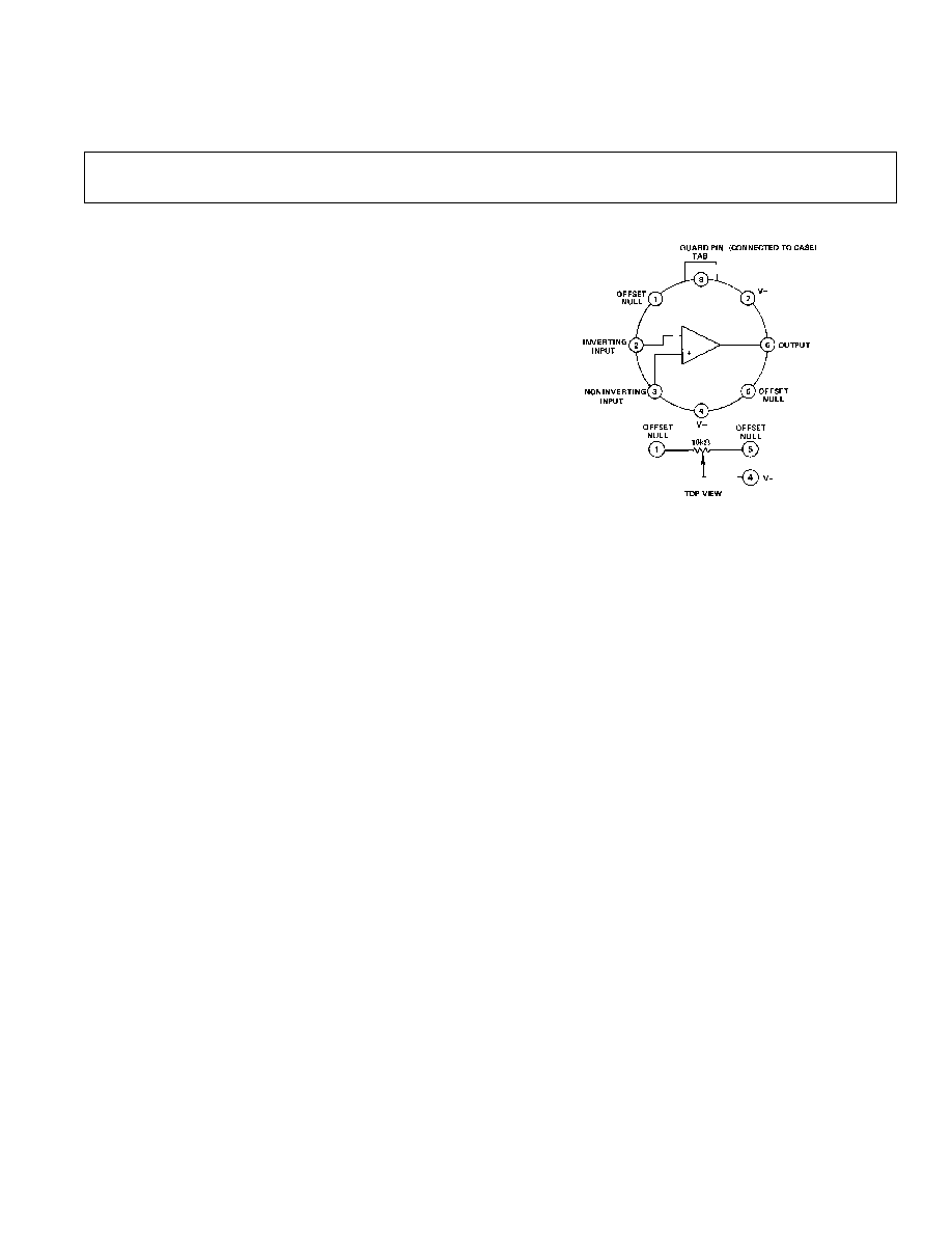
PIN CONFIGURATION
FEATURES
Ultralow Bias Current: 75 fA max (AD515AL)
Ultralow Bias Current:
150 fA max (AD515AK)
Ultralow Bias Current:
300 fA max (AD515AJ)
Low Power: 1.5 mA max Quiescent Current
Low Power:
(0.6 mA typ)
Low Offset Voltage: 1.0 mV max (AD515AK & L)
Low Drift: 15 V/ C max (AD515AK)
Low Noise: 4 V p-p, 0.1 Hz to 10 Hz
PRODUCT DESCRIPTION
The AD515A is a monolithic FET-input operational amplifier
with a guaranteed maximum input bias current of 75 fA
(AD515AL). The AD515A is a monolithic successor to the
industry standard AD515 electrometer, and will replace the
AD515 in most applications. The AD515A also delivers laser-
trimmed offset voltage, low drift, low noise and low power, a
combination of features not previously available in ultralow bias
current circuits. All devices are internally compensated, protected
against latch-up and are short circuit protected.
The AD515A's combination of low input bias current, low
offset voltage and low drift optimizes it for a wide variety of
electrometer and very high impedance buffer applications
including photocurrent detection, vacuum ion-gage measure-
ment, long-term precision integration and low drift sample/hold
applications. This amplifier is also an excellent choice for all forms
of biomedical instrumentation such as pH/pIon sensitive elec-
trodes, very low current oxygen sensors, and high impedance
biological microprobes. In addition, the low cost and pin
compatibility of the AD515A with standard FET op amps will
allow designers to upgrade the performance of present systems
at little or no additional cost. The 10
15
common-mode input
impedance ensures that the input bias current is essentially
independent of common-mode voltage.
As with previous electrometer amplifier designs from Analog
Devices, the case is brought out to its own connection (Pin 8)
so it can be independently connected to a point at the same
potential as the input, thus minimizing stray leakage to the case.
This feature will also shield the input circuitry from external
noise and supply transients.
The AD515A is available in three versions of bias current and
offset voltage, the "J", "K" and "L"; all are specified for rated
performance from 0
∞
C to +70
∞
C and supplied in a hermetically
sealed TO-99 package.
PRODUCT HIGHLIGHTS
1. The AD515A provides subpicoampere bias currents in an
integrated circuit amplifier.
∑ The ultralow input bias currents are specified as the maxi-
mum measured at either input with the device fully warmed
up on
±
15 V supplies at +25
∞
C ambient with no heat sink.
This parameter is 100% tested.
∑ By using
±
5 V supplies, input bias current can typically be
brought below 50 fA.
2. The input offset voltage on all grades is laser trimmed, typically
less than 500
µ
V.
∑ The offset voltage drift is 15
µ
V/
∞
C maximum on the
K grade.
∑ If additional pulling is desired, the amount required will
have a minimal effect on offset drift (approximately 3
µ
V/
∞
C
per mV).
3. The low quiescent current drain of 0.6 mA typical and
1.5 mA maximum, keeps self-heating effects to a minimum
and renders the AD515A suitable for a wide range of remote
probe applications.
4. The combination of low input noise voltage and very low
input noise current is such that for source impedances from
1M
to 10
11
, the Johnson noise of the source will easily
dominate the noise characteristic.

≠2≠
REV. A
AD515A≠SPECIFICATIONS
Model
AD515AJ
AD515AK
AD515AL
OPEN-LOOP GAIN
1
V
OUT
=
±
10 V, R
L
2 k
20,000 V/V min
40,000 V/V min
25,000 V/V min
V
OUT
=
±
10 V,
R
L
10 k
40,000 V/V min
100,000 V/V min
50,000 V/V min
T
A
= min to max R
L
2 k
15,000 V/V min
40,000 V/V min
25,000 V/V min
OUTPUT CHARACTERISTICS
Voltage @ R
L
= 2 k
, T
A
= min to max
10 V min ( 12 V typ)
*
*
Voltage
@ R
L
= 10 k
, T
A
= min to max
12 V min ( 13 V typ)
*
*
Load Capacitance
2
1000 pF
Short-Circuit Current
10 mA min (20 mA typ)
FREQUENCY RESPONSE
Unity Gain, Small Signal
1 MHz
*
*
Full Power Response
5 kHz min (50 kHz typ)
*
*
Slew Rate Inverting Unity Gain
0.3 V/
µ
s min (3.0 V/
µ
s typ)
*
*
Overload Recovery Inverting Unity Gain
100
µ
s max (2
µ
s typ)
*
*
INPUT OFFSET VOLTAGE
3
3.0 mV max (0.4 mV typ)
1.0 mV max (0.4 mV typ)
1.0 mV max (0.4 mV typ)
vs. Temperature, T
A
= min to max
50 V/ C max
15 V/ C max
25 V/ C max
vs. Supply, T
A
= min to max
400 V/V max (50 V/V typ)
100 V/V max
200 V/V max
INPUT BIAS CURRENT
Either Input
4
300 fA max
150 fA max
75 fA max
INPUT IMPEDANCE
Differential V
DIFF
=
±
1 V
1.6 pF 10
13
*
*
Common Mode
0.8 pF 10
15
*
*
INPUT NOISE
Voltage, 0.1 Hz to 10 Hz
4.0
µ
V (p-p)
*
*
f = 10 Hz
75 nV/V/
Hz
*
*
f = 100 Hz
55 nV/
Hz
*
*
f = l kHz
50 nV/
Hz
*
*
Current, 0.1 Hz to 10 Hz
0.007 pA (p-p)
*
*
10 Hz to 10 kHz
0.01 pA rms
*
*
INPUT VOLTAGE RANGE
Differential
20 V min
*
*
Common Mode, T
A
= min to max
10 V min (+ 12 V, ≠11 typ)
*
*
Common-Mode Rejection, V
IN
=
±
10 V
66 dB min (94 dB typ)
80 dB min
70 dB min
Maximum Safe Input Voltage
5
±
V
S
*
*
POWER SUPPLY
Rated Performance
±
15 V
*
*
Operating
5 V min ( 18 V max)
*
*
Quiescent Current
1.5 mA max (0.6 mA typ)
*
TEMPERATURE
Operating, Rated Performance
0
∞
C to + 70
∞
C
*
*
Storage
≠65
∞
C to +150
∞
C
PACKAGE OPTION
TO-99 (H-08A)
AD515AJH
AD515AKH
AD515ALH
(typical @ +25 C and V
S
= 15 V dc, unless otherwise noted)
NOTES
*Specifications same as AD515AJ.
1
Open Loop Gain is specified with or without pulling of V
OS
.
2
A conservative design would not exceed 750 pF of load capacitance.
3
Input Offset Voltage specifications are guaranteed after 5 minutes of
operation at T
A
= +25
∞
C.
4
Bias Current specifications are guaranteed after 5 minutes of operation at
T
A
= +25
∞
C. For higher temperatures, the current doubles every +10
∞
C.
5
1f it is possible for the input voltage to exceed the supply voltage, a series
protection resistor should be added to limit input current to 0.1 mA.
The input devices can handle overload currents of 0.1 mA indefinitely without
damage. See next page.
Specifications shown in boldface are tested on all production units at final test.
Specifications subject to change without notice.
WARNING!
ESD SENSITIVE DEVICE
CAUTION
ESD (electrostatic discharge) sensitive device. Electrostatic charges as high as 4000 V readily
accumulate on the human body and test equipment and can discharge without detection.
Although the AD515A features proprietary ESD protection circuitry, permanent damage may
occur on devices subjected to high energy electrostatic discharges. Therefore, proper ESD
precautions are recommended to avoid performance degradation or loss of functionality.
≠3≠
REV. A
AD515A
LAYOUT AND CONNECTIONS CONSIDERATIONS
The design of very high impedance measurement systems in-
troduces a new level of problems associated with the reduction
of leakage paths and noise pickup.
1. A primary consideration in high impedance system designs is
to attempt to place the measuring device as near to the signal
source as possible. This will minimize current leakage paths,
noise pickup and capacitive loading. The AD515A, with its
combination of low offset voltage (normally eliminating the
need for trimming), low quiescent current (minimal source
heating, possible battery operation), internal compensation
and small physical size lends itself to installation at the signal
source or inside a probe. As a result of the high load capaci-
tance rating, the AD515A can comfortably drive a long
signal cable.
2. The use of guarding techniques is essential to realizing the
capability of the ultralow input currents of the AD515A.
Guarding is achieved by applying a low impedance bootstrap
potential to the outside of the insulation material surround-
ing the high impedance signal line. This bootstrap potential
is held at the same level as that of the high impedance line;
therefore, there is no voltage drop across the insulation and,
hence, no leakage. The guard will also act as a shield to
reduce noise pickup and serves an additional function of
reducing the effective capacitance to the input line. The case
of the AD515A is brought out separately to Pin 8 so it can
also be connected to the guard potential. This technique
virtually eliminates potential leakage paths across the package
insulation, provides a noise shield for the sensitive circuitry
and reduces common-mode input capacitance to about 0.8
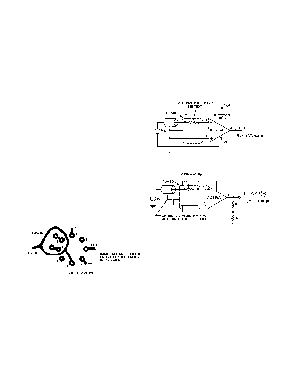
pF. Figure 1 shows a proper printed circuit board layout for
input guarding and connecting the case guard. Figures 2 and
3 show guarding connections for typical inverting and
noninverting applications. If Pin 8 is not used for guarding, it
should be connected to ground or a power supply to reduce
noise.
Figure 1. Board Layout for Guarding Inputs with Guarded
TO-99 Package
3. Printed circuit board layout and construction is critical for
achieving the ultimate in low leakage performance that the
AD515A can deliver. The best performance will be realized
by using a teflon IC socket for the AD515A; at a minimum a
teflon standoff should be used for the high impedance lead.
If this is not feasible, the input guarding scheme shown in
Figure 1 will minimize leakage as much as possible; the
guard ring should be applied to both sides of the board. The
guard ring is connected to a low impedance potential at the
same level as the inputs. High impedance signal lines should
not be extended for any unnecessary length on a printed
circuit; to minimize noise and leakage, they must be carried
in rigid, shielded cables.
4. Another important concern for achieving and maintaining
low leakage currents is complete cleanliness of circuit boards
and components. Completed assemblies should be washed
thoroughly in a low residue solvent such as TMC Freon or
high purity methanol, followed by a rinse with deionized
water and nitrogen drying. If service is anticipated in a high
contaminant or high humidity environment, a high dielectric
conformal coating is recommended. All insulation materials
except Kel-F or teflon will show rapid degradation of surface
leakage at high humidities.
Figure 2. Picoampere Current-to-Voltage Converter
Inverting Configuration
Figure 3. Very High Impedance Noninverting Amplifier
INPUT PROTECTION
The AD515A is guaranteed for a maximum safe input potential
equal to the power supply potential.
Many instrumentation situations, such as flame detectors in gas
chromatographs, involve measurement of low level currents
from high voltage sources. In such applications, a sensor fault
condition may apply a very high potential to the input of the
current-to-voltage converting amplifier. This possibility necessi-
tates some form of input protection. Many electrometer type
devices, especially CMOS designs, can require elaborate Zener
protection schemes that often compromise overall performance.
The AD515A requires input protection only if the source is not
current limited and, as such, is similar to many JFET-input
designs. The failure mode would be overheating from excess
current rather than voltage breakdown. If the source is not
current limited, all that is required is a resistor in series with the
affected input terminal so that the maximum overload current is
0.1 mA (for example, 1 M
for a 100 V overload). This simple
scheme will cause no significant reduction in performance and
give complete overload protection. Figures 2 and 3 show proper
connections.

AD515A
≠4≠
REV. A
COAXIAL CABLE AND CAPACITANCE EFFECTS
If it is not possible to attach the AD515A virtually on top of the
signal source, considerable care should be exercised in designing
the connecting lines carrying the high impedance signal. Shielded
coaxial cable must be used for noise reduction, but use of
coaxial cables for high impedance work can add problems from
cable leakage, noise and capacitance. Only the best polyethylene
or virgin teflon (not reconstituted) should be used to obtain the
highest possible insulation resistance.
Cable systems should be made as rigid and vibration free as
possible since cable movement can cause noise signals of three
types, all significant in high impedance systems. Frictional
movement of the shield over the insulation material generates a
charge that is sensed by the signal line as a noise voltage. Low
noise cable with graphite lubricant such as Amphenol 21-537
will reduce the noise, but short rigid lines are better. Cable
movements will also make small changes in the internal cable
capacitance and capacitance to other objects. Since the total
charge on these capacitances cannot be instantly changed, a
noise voltage results, as predicted from:
V = Q/
C. Noise
voltage is also generated by the motion of a conductor in a
magnetic field.
The conductor-to-shield capacitance of coaxial cable is usually
about 30 pF/foot. Charging this capacitance can cause consider-
able stretching of high impedance signal rise time, thus cancel-
ling the low input capacitance feature of the AD515A. There are
two ways to circumvent this problem. For inverting signals or
low level current measurements, the signal is carried on the line
connected to the inverting input and shielded (guarded) by the
ground line as shown in Figure 2. Since the signal is always at
virtual ground, no voltage change is required and no capaci-
tances are charged. In many circumstances, this will destabilize
the circuit; if so, capacitance from output to inverting input will
stabilize the circuit.
Noninverting and buffer situations are more critical since the
signal line voltage and therefore charge will change, causing
signal delay. This effect can be considerably reduced by
connecting the cable shield to a guard potential instead of
ground, an option shown in Figure 3. Since such a connection
results in positive feedback to the input, the circuit may be
destabilized and oscillate. If so, capacitance from positive input
to ground must be added to make the net capacitance at Pin 3
positive. This technique can considerably reduce the effective
capacitance that must be charged.
Typical Performance Curves
Figure 4. PSRR and CMRR vs. Frequency
Figure 5. Open Loop Frequency Response
Figure 6. Input Common-Mode Range vs. Supply Voltage
Figure 7. Peak-to-Peak Input Noise Voltage vs. Source
Impedance and Bandwidth

AD515A
≠5≠
REV. A
ELECTROMETER APPLICATION NOTES
The AD515A offers subpicoampere input bias currents available
in an integrated circuit package. This design will open up many
new application opportunities for measurements from very high
impedance and very low current sources. Performing accurate
measurements of this sort requires careful attention to detail;
the notes given here will aid the user in realizing the full
measurement potential of the AD515A and perhaps extending
its performance limits.
1. As with all junction FET input devices, the temperature of
the FETs themselves is critical in determining the input bias
currents. Over the operating temperature range, the input
bias currents closely follow a characteristic of doubling every
10
∞
C; therefore, every effort should be made to minimize
device operating temperature.
2. The heat dissipation can be reduced initially by careful
investigation of the application. First, if it is possible to
reduce the required power supplies, this should be done
since internal power consumption contributes the largest
component of self-heating. To minimize this effect, the
quiescent current of the AD515A has been reduced to less
than 1 mA. Figure 8 shows typical input bias current and
quiescent current versus supply voltage.
3. Output loading effects, which are normally ignored, can
cause a significant increase in chip temperature and therefore
bias current. For example, a 2 k
load driven at 10 V at the
output will cause at least an additional 25 mW dissipation in
the output stage (and some in other stages) over the typical
24 mW, thereby at least doubling the effects of self-heating.
The results of this form of additional power dissipation are
demonstrated in Figure 9, which shows normalized input
bias current versus additional power dissipated. Therefore,
although many dc performance parameters are specified
driving a 2 k
load, to reduce this additional dissipation, we
recommend restricting the load resistance to be at least 10 k
.
4. Figure 10 shows the AD515A's input current versus differen-
tial input voltage. Input current at either terminal stays below
a few hundred fA until one input terminal is forced higher
than 1 V to 1.5 V above the other terminal. Input current
limits at 30
µ
A under these conditions.
Figure 8. Input Bias Current and Supply Current vs.
Supply Voltage
Figure 9. Input Bias Current vs. Additional Power
Dissipation
Figure 10. Input Bias Current vs. Differential Input Voltage
AD515A CIRCUIT APPLICATION NOTES
The AD515A is quite simple to apply to a wide variety of
applications because of the pretrimmed offset voltage and
internal compensation, which minimize required external
components and eliminate the need for adjustments to the
device itself. The major considerations in applying this device
are the external problems of layout and heat control which have
already been discussed. In circuit situations employing the use of
very high value resistors, such as low level current to voltage
converters, electrometer operational amplifiers can be destabi-
lized by a pole created by the small capacitance at the negative
input. If this occurs, a capacitor of 2 pF to 5 pF in parallel with
the resistor will stabilize the loop. A much larger capacitor may
be used if desired to limit bandwidth and thereby reduce wide-
band noise.
Selection of passive components employed in high impedance
film or deposited ceramic oxide to obtain the best in low noise
and high stability performance. The best packaging for high
M
resistors is a glass body sprayed with silicone varnish to
minimize humidity effects. These resistors must be handled
very carefully to prevent surface contamination. Capacitors for
any high impedance or long-term integration situation should
be of a polystyrene formulation for optimum performance.
Most other types have too low an insulation resistance, or high
dielectric absorption.
Unlike situations involving standard operational amplifiers with
much higher bias currents, balancing the impedances seen at
the input terminals of the AD515A is usually unnecessary and
probably undesirable. At the large source impedances, where
these effects matter, obtaining quality matched resistors will be
difficult. More important, instead of a cancelling effect, as with
bias current, the noise voltage of the additional resistor will add
by root-sum-of-squares to that of the other resistor thus increasing