1214-370MR4
APT-RF, Inc. reserves the right to make changes without further notice. APT-RF recommends that before the product(s) described herein are written into
specifications, or used in critical applications, that the performance characteristics be verified by contacting the factory.
APT-RF, Inc. 3000 Oakmead Village Drive, Santa Clara, CA 95051-0808 TEL. 408-986-8031 FAX 408-869-2324
.
GENERAL DESCRIPTION
The 1214-370M is an internally matched, COMMON BASE transistor
capable of providing 370 Watts of pulsed RF output power at 330
microseconds pulse width, ten percent duty factor across the band 1200 to
1400 MHz. This hermetically solder-sealed transistor is specifically designed
for L-Band radar applications. It utilizes gold metallization and diffused
emitter ballasting to provide high reliability and supreme ruggedness.
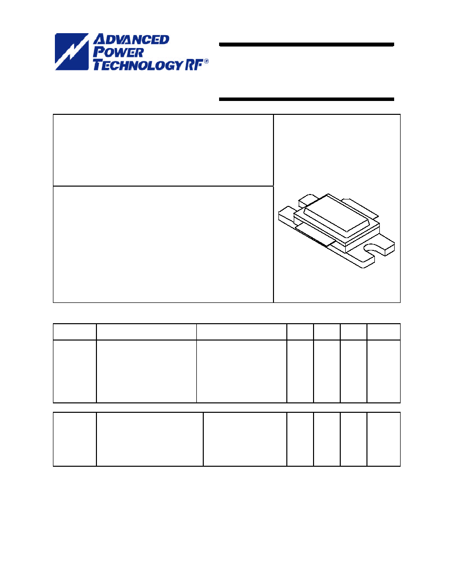
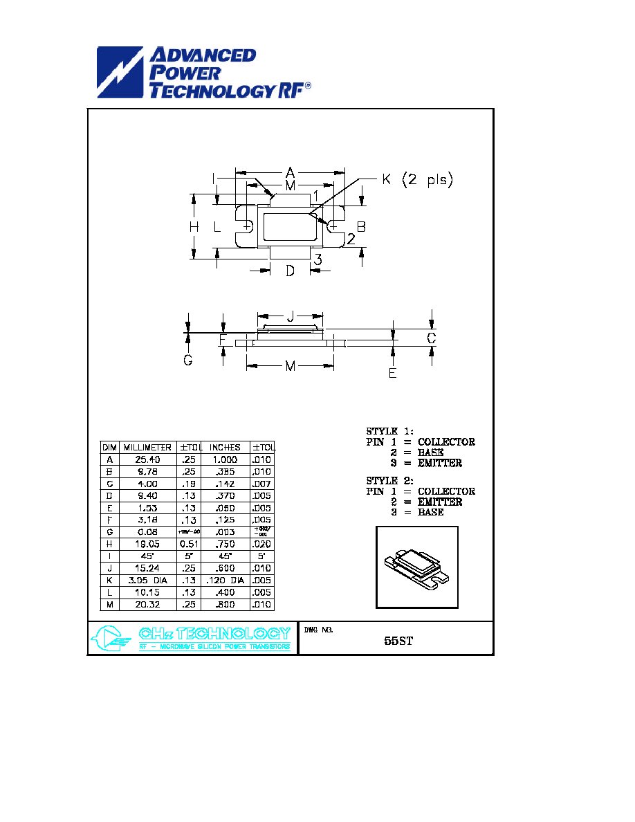
CASE OUTLINE
55ST, STYLE 1
ABSOLUTE MAXIMUM RATINGS
Maximum Power Dissipation @ 25
o
C
1
600 Watts
Maximum Voltage and Current
BVces Collector to Emitter Voltage 75 Volts
BVebo Emitter to Base Voltage 3.0 Volts
Ic Collector Current 25 Amps
Maximum Temperatures
Storage Temperature - 65 to + 200
o
C
Operating Junction Temperature + 200
o
C
ELECTRICAL CHARACTERISTICS @ 25
O
C
SYMBOL
CHARACTERISTICS
TEST CONDITIONS
MIN
TYP
MAX
UNITS
Pout
Pg
c
Pd
VSWR
1
Power Out (Note 2) Pulsed
Power Gain
Collector Efficiency
Pulse Amplitude Droop
Load Mismatch Tolerance
F = 1200-1400 MHz
Vcc = 50 Volts,
Pulse Width = 330
�
s
Duty = 10 %
As above
F = 1400MHz, Po =370W
370
8.7
50
9.0
460
0.5
2:1
Watts
dB
%
dB
** Design Target
Bvces
Ices
Iebo
Hfe
jc
1
Collector to Emitter Breakdown
Collector to Emitter Leakage
Emitter to Base Leakage Current
DC Current Gain
Thermal Resistance
Ic = 40 mA
Vce = 50 Volts
Veb = 3.0 Volts
Vce = 5 V, Ic = 5 A
Rated Pulse Condition
75
10
45
10
5
0.29
Volts
mA
mA
o
C/W
Issue April 2005
Note 1: Pulse width = 330 us, duty = 10%
Note 2: Power Input = 50 Watts Peak Pulsed
1214 � 370M
370 Watts - 50 Volts, 330
�
s, 10%
Radar 1200 - 1400 MHz

1214-370MR4
APT-RF, Inc. reserves the right to make changes without further notice. APT-RF recommends that before the product(s) described herein are written into
specifications, or used in critical applications, that the performance characteristics be verified by contacting the factory.
APT-RF, Inc. 3000 Oakmead Village Drive, Santa Clara, CA 95051-0808 TEL. 408-986-8031 FAX 408-869-2324
.
1214-370M
Performance Curves
1214-370M
Power Out vs Pin
0
50
100
150
200
250
300
350
400
450
25
35
40
50
63
Power Input
Power Output
Pout 1200 MHz
Pout 1300 MHz
Pout 1400 MHz
1214-370M
Efficiency vs Power Input
0
10
20
30
40
50
60
70
80
25
35
40
50
63
Power Input - Watts
Efficiency - %
1200 MHz
1300 MHz
1400 MHz
1214-370M
Power Gain vs Power Input
7
7.5
8
8.5
9
9.5
10
25
35
40
50
63
Power Input - Watts
Power Gain - dB
1200 MHz
1300 MHz
1400 MHz
Impedance Information
Output
Matching
Circuit
Input
Matching
Circuit
50 Ohms
50 Ohms
Z
Source
Z
Load
Impedance
Freq
Zs
Zl
1200 1.75-j2.23
1.52-j2.11
1300 1.75-j1.63
1.36-j1.97
1400 1.76-j1.19
1.13-j1.77
Board Material RT 6010.5 LM 25 Mil
TRL Measurement

1214-370MR4
APT-RF, Inc. reserves the right to make changes without further notice. APT-RF recommends that before the product(s) described herein are written into
specifications, or used in critical applications, that the performance characteristics be verified by contacting the factory.
APT-RF, Inc. 3000 Oakmead Village Drive, Santa Clara, CA 95051-0808 TEL. 408-986-8031 FAX 408-869-2324
1214-370M
Broadband Test Fixture
1214-370MR4
APT-RF, Inc. reserves the right to make changes without further notice. APT-RF recommends that before the product(s) described herein are written into
specifications, or used in critical applications, that the performance characteristics be verified by contacting the factory.
APT-RF, Inc. 3000 Oakmead Village Drive, Santa Clara, CA 95051-0808 TEL. 408-986-8031 FAX 408-869-2324
1214-370M