1-385
H
High Bandwidth, Analog/Video
Optocouplers
Technical Data
Features
∑ Wide Bandwidth
[1]
:
17 MHz (HCPL-4562)
9 MHz (HCNW4562)
∑ High Voltage Gain
[1]
:
2.0 (HCPL-4562)
3.0 (HCNW4562)
∑ Low G
V
Temperature
Coefficient: -0.3%/
∞
C
∑ Highly Linear at Low Drive
Currents
∑ High-Speed AlGaAs Emitter
∑ Safety Approval
UL Recognized - 2500 V rms
for 1 minute (5000 V rms for
1 minute for HCPL-
4562#020 and HCNW4562)
per UL 1577
CSA Approved
VDE 0884 Approved
-V
IORM
= 1414 V
peak
for
HCNW4562
BSI Certified (HCNW4562)
∑ Available in 8-Pin DIP and
Widebody Packages
Applications
∑ Video Isolation for the
Following Standards/
Formats: NTSC, PAL,
SECAM, S-VHS, ANALOG
RGB
∑ Low Drive Current Feedback
Element in Switching Power
Supplies, e.g., for ISDN
Networks
∑ A/D Converter Signal
Isolation
∑ Analog Signal Ground
Isolation
∑ High Voltage Insulation
Description
The HCPL-4562 and HCNW4562
optocouplers provide wide band-
width isolation for analog signals.
They are ideal for video isolation
when combined with their
application circuit (Figure 4).
High linearity and low phase shift
are achieved through an AlGaAs
LED combined with a high speed
detector. These single channel
optocouplers are available in
8-Pin DIP and Widebody package
configurations.
HCPL-4562
HCNW4562
CAUTION: It is advised that normal static precautions be taken in handling and assembly of this component to
prevent damage and/or degradation which may be induced by ESD.
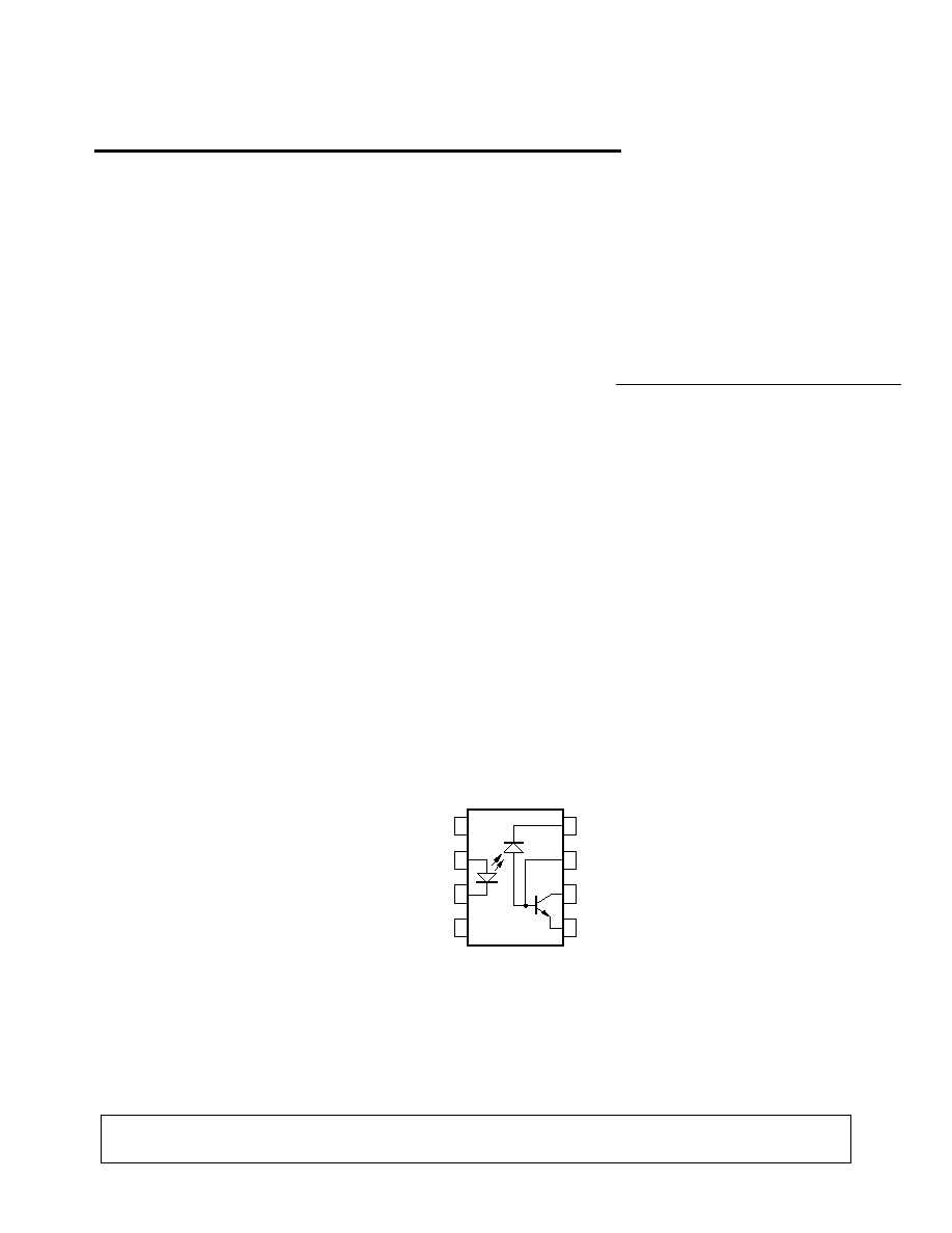
Functional Diagram
7
1
2
3
4
5
6
8
NC
ANODE
CATHODE
NC
VCC
VB
VO
GND
5965-3579E

1-386
Selection Guide
Single Channel Packages
8-Pin DIP
Widebody
(300 Mil)
(400 Mil)
HCPL-4562
HCNW4562
Ordering Information
Specify Part Number followed by Option Number (if desired).
Example:
HCPL-4562#XXX
020 = UL 5000 V rms/1 Minute Option*
300 = Gull Wing Surface Mount Option
500 = Tape and Reel Packaging Option
Option data sheets are available. Contact your Hewlett-Packard sales representative or authorized
distributor for information.
*For HCPL-4562 only.
Gull wing surface mount option applies to through hole parts only.
Schematic
IF
8
6
5
GND
VCC
2
3
VO
ICC
VF
IO
ANODE
CATHODE
+
≠
7
VB
IB
1-387
Package Outline Drawings
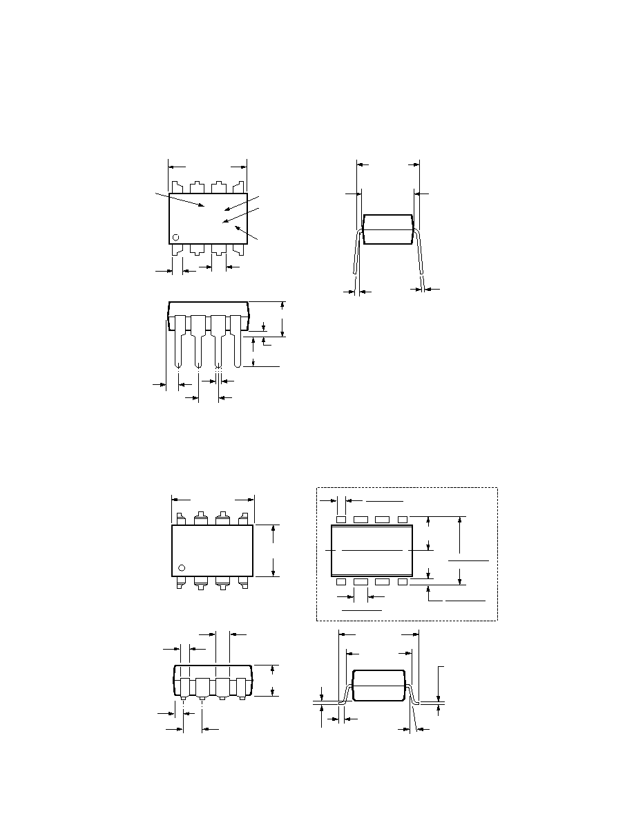
8-Pin DIP Package (HCPL-4562)
8-Pin DIP Package with Gull Wing Surface Mount Option 300 (HCPL-4562)
0.635 ± 0.25
(0.025 ± 0.010)
12∞ NOM.
9.65 ± 0.25
(0.380 ± 0.010)
0.635 ± 0.130
(0.025 ± 0.005)
7.62 ± 0.25
(0.300 ± 0.010)
5
6
7
8
4
3
2
1
9.65 ± 0.25
(0.380 ± 0.010)
6.350 ± 0.25
(0.250 ± 0.010)
1.016 (0.040)
1.194 (0.047)
1.194 (0.047)
1.778 (0.070)
9.398 (0.370)
9.906 (0.390)
4.826
(0.190)
TYP.
0.381 (0.015)
0.635 (0.025)
PAD LOCATION (FOR REFERENCE ONLY)
1.080 ± 0.320
(0.043 ± 0.013)
4.19
(0.165)
MAX.
1.780
(0.070)
MAX.
1.19
(0.047)
MAX.
2.54
(0.100)
BSC
DIMENSIONS IN MILLIMETERS (INCHES).
LEAD COPLANARITY = 0.10 mm (0.004 INCHES).
0.254
+ 0.076
- 0.051
(0.010
+ 0.003)
- 0.002)
9.65 ± 0.25
(0.380 ± 0.010)
1.78 (0.070) MAX.
1.19 (0.047) MAX.
HP XXXXZ
YYWW
DATE CODE
1.080 ± 0.320
(0.043 ± 0.013)
2.54 ± 0.25
(0.100 ± 0.010)
0.51 (0.020) MIN.
0.65 (0.025) MAX.
4.70 (0.185) MAX.
2.92 (0.115) MIN.
DIMENSIONS IN MILLIMETERS AND (INCHES).
5
6
7
8
4
3
2
1
5∞ TYP.
OPTION NUMBER*
UL
RECOGNITION
UR
0.254
+ 0.076
- 0.051
(0.010
+ 0.003)
- 0.002)
7.62 ± 0.25
(0.300 ± 0.010)
6.35 ± 0.25
(0.250 ± 0.010)
* MARKING CODE LETTER FOR OPTION NUMBERS.
"L" = OPTION 020
"V" = OPTION 060
OPTION NUMBERS 300 AND 500 NOT MARKED.
TYPE NUMBER
1-388
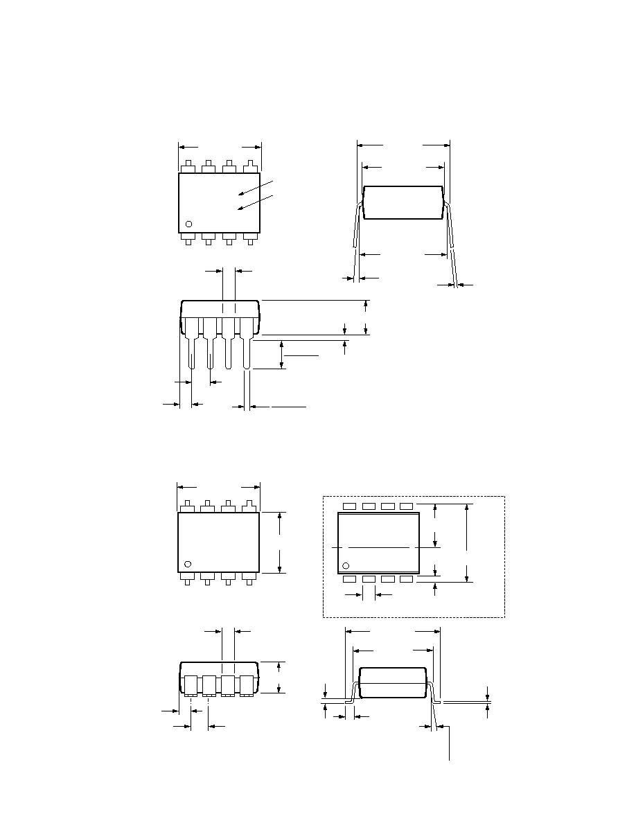
8-Pin Widebody DIP Package (HCNW4562)
8-Pin Widebody DIP Package with Gull Wing Surface Mount Option 300 (HCNW4562)
5
6
7
8
4
3
2
1
11.15 ± 0.15
(0.442 ± 0.006)
1.78 ± 0.15
(0.070 ± 0.006)
5.10
(0.201)
MAX.
1.55
(0.061)
MAX.
2.54 (0.100)
TYP.
DIMENSIONS IN MILLIMETERS (INCHES).
7∞ TYP.
0.254
+ 0.076
- 0.0051
(0.010
+ 0.003)
- 0.002)
11.00
(0.433)
9.00 ± 0.15
(0.354 ± 0.006)
MAX.
10.16 (0.400)
TYP.
HP
HCNWXXXX
YYWW
DATE CODE
TYPE NUMBER
0.51 (0.021) MIN.
0.40 (0.016)
0.56 (0.022)
3.10 (0.122)
3.90 (0.154)
1.00 ± 0.15
(0.039 ± 0.006)
7∞ NOM.
12.30 ± 0.30
(0.484 ± 0.012)
0.75 ± 0.25
(0.030 ± 0.010)
11.00
(0.433)
5
6
7
8
4
3
2
1
11.15 ± 0.15
(0.442 ± 0.006)
9.00 ± 0.15
(0.354 ± 0.006)
1.3
(0.051)
12.30 ± 0.30
(0.484 ± 0.012)
6.15
(0.242)TYP.
0.9
(0.035)
PAD LOCATION (FOR REFERENCE ONLY)
1.78 ± 0.15
(0.070 ± 0.006)
4.00
(0.158)
MAX.
1.55
(0.061)
MAX.
2.54
(0.100)
BSC
DIMENSIONS IN MILLIMETERS (INCHES).
LEAD COPLANARITY = 0.10 mm (0.004 INCHES).
0.254
+ 0.076
- 0.0051
(0.010
+ 0.003)
- 0.002)
MAX.
1-389
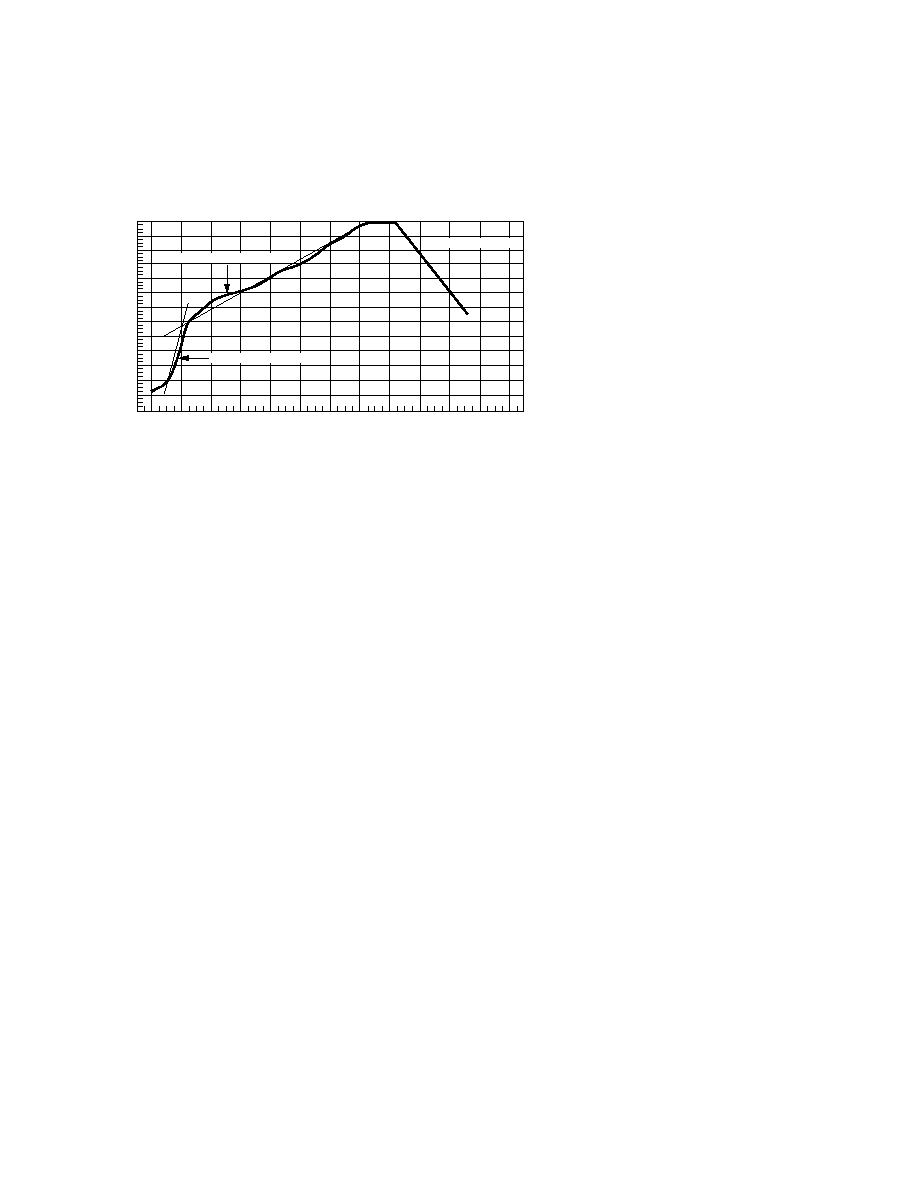
Note: Use of nonchlorine activated fluxes is highly recommended.
240
T = 115∞C, 0.3∞C/SEC
0
T = 100∞C, 1.5∞C/SEC
T = 145∞C, 1∞C/SEC
TIME ≠ MINUTES
TEMPERATURE ≠ ∞C
220
200
180
160
140
120
100
80
60
40
20
0
260
1
2
3
4
5
6
7
8
9
10
11
12
Solder Reflow Temperature Profile (Gull Wing Surface Mount Option Parts)
Regulatory Information
The devices contained in this data
sheet have been approved by the
following organizations:
UL
Recognized under UL 1577,
Component Recognition
Program, File E55361.
CSA
Approved under CSA Component
Acceptance Notice #5, File CA
88324.
VDE
Approved according to VDE
0884/06.92 (HCNW4562 only).
BSI
Certification according to
BS415:1994
(BS EN60065:1994);
BS EN60950:1992
(BS7002:1992) and
EN41003:1993 for Class II
applications (HCNW4562 only).