
1-33
H
High CMR, High Speed
Optocouplers
Technical Data
HCPL-4504
HCPL-0454
HCNW4504
Features
∑ Short Propagation Delays
for TTL and IPM
Applications
∑ 15 kV/
µ
s Minimum Common
Mode Transient Immunity at
V
CM
= 1500 V for TTL/Load
Drive
∑ High CTR at T
A
= 25
∞
C
>25% for HCPL-4504/0454
>23% for HCNW4504
∑ Electrical Specifications for
Common IPM Applications
∑ TTL Compatible
∑ Guaranteed Performance
from 0
∞
C to 70
∞
C
∑ Open Collector Output
∑ Safety Approval
UL Recognized - 2500 V rms
for 1 minute (5000 V rms for
1 minute for
HCPL-4504#020 and
HCNW4504)per UL1577
CSA Approved
VDE 0884 Approved
-V
IORM
= 630 V
peak
for
HCPL-4504#060
-V
IORM
= 1414 V
peak
for
HCNW4504
BSI Certified (HCNW4504)
∑ Available in 8-Pin DIP, SO-8,
Widebody Packages
Applications
∑ Inverter Circuits and
Intelligent Power Module
(IPM) interfacing -
High Common Mode Transient
Immunity (> 10 kV/
µ
s for an
IPM load/drive) and (t
PLH
- t
PHL
)
Specified (See Power Inverter
Dead Time section)
∑ Line Receivers -
Short Propagation Delays and
Low Input-Output Capacitance
∑ High Speed Logic Ground
Isolation - TTL/TTL, TTL/
CMOS, TTL/LSTTL
∑ Replaces Pulse
Transformers -
Save Board Space and Weight
∑ Analog Signal Ground
Isolation -
Integrated Photodetector
Provides Improved Linearity
over Phototransistors
Functional Diagram
CAUTION: It is advised that normal static precautions be taken in handling and assembly of this component to
prevent damage and/or degradation which may be induced by ESD.
A 0.1
µ
F bypass capacitor between pins 5 and 8 is recommended.
7
1
2
3
4
5
6
8
NC
ANODE
CATHODE
NC
VCC
NC
VO
GND
TRUTH TABLE
LED
ON
OFF
VO
LOW
HIGH
Description
These optocouplers are similar to
HP's other high speed transistor
optocouplers but with shorter
propagation delays and higher
CTR. The HCPL-4504/0454 and
HCNW4504 also have a guaran-
teed propagation delay difference
(t
PLH
- t
PHL
). These features make
these optocouplers an excellent
solution to IPM inverter dead time
and other switching problems.
5965-3604E

1-34
The HCPL-4504/0454 and
HCNW4504 CTR, propagation
delay, and CMR are specified for
both TTL and IPM load/drive
conditions. Specifications and
typical performance plots for both
TTL and IPM conditions are
provided for ease of application.
These single channel, diode-
transistor optocouplers are
available in 8-Pin DIP, SO-8, and
Widebody package configura-
tions. An insulating layer between
a LED and an integrated
photodetector provide electrical
insulation between input and
output. Separate connections for
Selection Guide
Single Channel Packages
8-Pin DIP
Small Outline
Widebody
(300 Mil)
SO-8
(400 Mil)
HCPL-4504
HCPL-0454
HCNW4504
Ordering Information
Specify Part Number followed by Option Number (if desired).
Example:
HCPL-4504#XXX
020 = UL 5000 V rms/1 Minute Option*
060 = VDE 0884 V
IORM
= 630 V
peak
Option*
300 = Gull Wing Surface Mount Option
500 = Tape and Reel Packaging Option
Option data sheets available. Contact your Hewlett-Packard sales representative or authorized distributor for
information.
*For HCPL-4504 only. Combination of Option 020 and Option 060 is not available.
Gull wing surface mount option applies to through hole parts only.
Schematic
IF
SHIELD
8
6
5
GND
VCC
2
3
VO
ICC
VF
IO
ANODE
CATHODE
+
≠
the photodiode bias and output-
transistor collector increase the
speed up to a hundred times that
of a conventional phototransistor
coupler by reducing the base
collector capacitance.

1-35
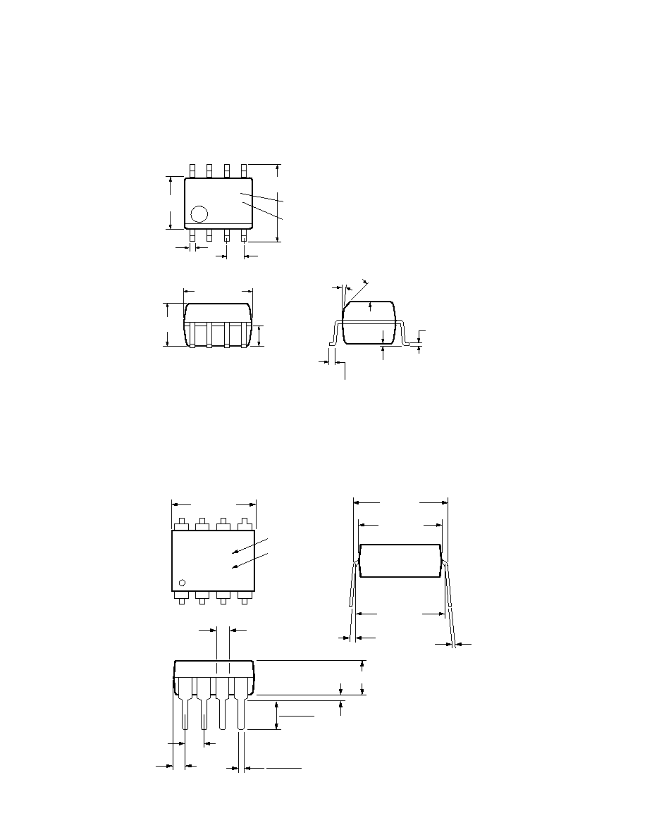
Package Outline Drawings
8-Pin DIP Package (HCPL-4504)
8-Pin DIP Package with Gull Wing Surface Mount Option 300 (HCPL-4504)
0.635 ± 0.25
(0.025 ± 0.010)
12∞ NOM.
9.65 ± 0.25
(0.380 ± 0.010)
0.635 ± 0.130
(0.025 ± 0.005)
7.62 ± 0.25
(0.300 ± 0.010)
5
6
7
8
4
3
2
1
9.65 ± 0.25
(0.380 ± 0.010)
6.350 ± 0.25
(0.250 ± 0.010)
1.016 (0.040)
1.194 (0.047)
1.194 (0.047)
1.778 (0.070)
9.398 (0.370)
9.906 (0.390)
4.826
(0.190)
TYP.
0.381 (0.015)
0.635 (0.025)
PAD LOCATION (FOR REFERENCE ONLY)
1.080 ± 0.320
(0.043 ± 0.013)
4.19
(0.165)
MAX.
1.780
(0.070)
MAX.
1.19
(0.047)
MAX.
2.54
(0.100)
BSC
DIMENSIONS IN MILLIMETERS (INCHES).
LEAD COPLANARITY = 0.10 mm (0.004 INCHES).
0.254
+ 0.076
- 0.051
(0.010
+ 0.003)
- 0.002)
9.65 ± 0.25
(0.380 ± 0.010)
1.78 (0.070) MAX.
1.19 (0.047) MAX.
HP XXXXZ
YYWW
DATE CODE
1.080 ± 0.320
(0.043 ± 0.013)
2.54 ± 0.25
(0.100 ± 0.010)
0.51 (0.020) MIN.
0.65 (0.025) MAX.
4.70 (0.185) MAX.
2.92 (0.115) MIN.
DIMENSIONS IN MILLIMETERS AND (INCHES).
5
6
7
8
4
3
2
1
5∞ TYP.
OPTION CODE*
UL
RECOGNITION
UR
0.254
+ 0.076
- 0.051
(0.010
+ 0.003)
- 0.002)
7.62 ± 0.25
(0.300 ± 0.010)
6.35 ± 0.25
(0.250 ± 0.010)
TYPE NUMBER
* MARKING CODE LETTER FOR OPTION NUMBERS.
"L" = OPTION 020
"V" = OPTION 060
OPTION NUMBERS 300 AND 500 NOT MARKED.
1-36
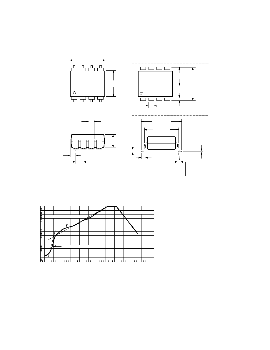
Small Outline SO-8 Package (HCPL-0454)
8-Pin Widebody DIP Package (HCNW4504)
XXX
YWW
8
7
6
5
4
3
2
1
5.842 ± 0.203
(0.236 ± 0.008)
3.937 ± 0.127
(0.155 ± 0.005)
0.381 ± 0.076
(0.016 ± 0.003)
1.270
(0.050)
BSG
5.080 ± 0.127
(0.200 ± 0.005)
3.175 ± 0.127
(0.125 ± 0.005)
1.524
(0.060)
45∞ X
0.432
(0.017)
0.228 ± 0.025
(0.009 ± 0.001)
TYPE NUMBER
(LAST 3 DIGITS)
DATE CODE
0.305
(0.012)
MIN.
DIMENSIONS IN MILLIMETERS (INCHES).
LEAD COPLANARITY = 0.10 mm (0.004 INCHES).
0.152 ± 0.051
(0.006 ± 0.002)
7∞
5
6
7
8
4
3
2
1
11.15 ± 0.15
(0.442 ± 0.006)
1.78 ± 0.15
(0.070 ± 0.006)
5.10
(0.201)
MAX.
1.55
(0.061)
MAX.
2.54 (0.100)
TYP.
DIMENSIONS IN MILLIMETERS (INCHES).
7∞ TYP.
0.254
+ 0.076
- 0.0051
(0.010
+ 0.003)
- 0.002)
11.00
(0.433)
9.00 ± 0.15
(0.354 ± 0.006)
MAX.
10.16 (0.400)
TYP.
HP
HCNWXXXX
YYWW
DATE CODE
TYPE NUMBER
0.51 (0.021) MIN.
0.40 (0.016)
0.56 (0.022)
3.10 (0.122)
3.90 (0.154)
1-37
8-Pin Widebody DIP Package with Gull Wing Surface Mount Option 300 (HCNW4504)
Note: Use of nonchlorine activated fluxes is highly recommended.
240
T = 115∞C, 0.3∞C/SEC
0
T = 100∞C, 1.5∞C/SEC
T = 145∞C, 1∞C/SEC
TIME ≠ MINUTES
TEMPERATURE ≠ ∞C
220
200
180
160
140
120
100
80
60
40
20
0
260
1
2
3
4
5
6
7
8
9
10
11
12
Solder Reflow Temperature Profile
(HCPL-0454 and Gull Wing Surface Mount Option Parts)
1.00 ± 0.15
(0.039 ± 0.006)
7∞ NOM.
12.30 ± 0.30
(0.484 ± 0.012)
0.75 ± 0.25
(0.030 ± 0.010)
11.00
(0.433)
5
6
7
8
4
3
2
1
11.15 ± 0.15
(0.442 ± 0.006)
9.00 ± 0.15
(0.354 ± 0.006)
1.3
(0.051)
12.30 ± 0.30
(0.484 ± 0.012)
6.15
(0.242)TYP.
0.9
(0.035)
PAD LOCATION (FOR REFERENCE ONLY)
1.78 ± 0.15
(0.070 ± 0.006)
4.00
(0.158)
MAX.
1.55
(0.061)
MAX.
2.54
(0.100)
BSC
DIMENSIONS IN MILLIMETERS (INCHES).
LEAD COPLANARITY = 0.10 mm (0.004 INCHES).
0.254
+ 0.076
- 0.0051
(0.010
+ 0.003)
- 0.002)
MAX.