 | –≠–ª–µ–∫—Ç—Ä–æ–Ω–Ω—ã–π –∫–æ–º–ø–æ–Ω–µ–Ω—Ç: HCPL-J454 | –°–∫–∞—á–∞—Ç—å:  PDF PDF  ZIP ZIP |
High CMR, High Speed
Optocouplers
Technical Data
HCPL-4504
HCPL-J454
HCPL-0454
HCNW4504
Features
∑ Short Propagation Delays
for TTL and IPM
Applications
∑ 15 kV/
µ
s Minimum Common
Mode Transient Immunity at
V
CM
= 1500 V for TTL/Load
Drive
∑ High CTR at T
A
= 25
∞
C
>25% for HCPL-4504/0454
>23% for HCNW4504
>19% for HCPL-J454
∑ Electrical Specifications for
Common IPM Applications
∑ TTL Compatible
∑ Guaranteed Performance
from 0
∞
C to 70
∞
C
∑ Open Collector Output
∑ Safety Approval
UL Recognized
- 3750 V rms / 1min. for
HCPL-4504/0454/J454
- 5000 V rms / 1min. for
HCPL-4504 Option020 and
HCNW4504
CSA Approved
IEC/EN/DIN EN 60747-5-2
Approved
- V
IORM
= 560 Vpeak for
HCPL-0454 Option060
- V
IORM
= 630 Vpeak for
HCPL-4504 Option060
- V
IORM
= 891 Vpeak for
HCPL-J454
- V
IORM
= 1414 Vpeak for
HCNW4504
Applications
∑ Inverter Circuits and
Intelligent Power Module
(IPM) interfacing -
High Common Mode Transient
Immunity (> 10 kV/
µ
s for an
IPM load/drive) and (t
PLH
- t
PHL
)
Specified (See Power Inverter
Dead Time section)
∑ Line Receivers -
Short Propagation Delays and
Low Input-Output Capacitance
∑ High Speed Logic Ground
Isolation - TTL/TTL, TTL/
CMOS, TTL/LSTTL
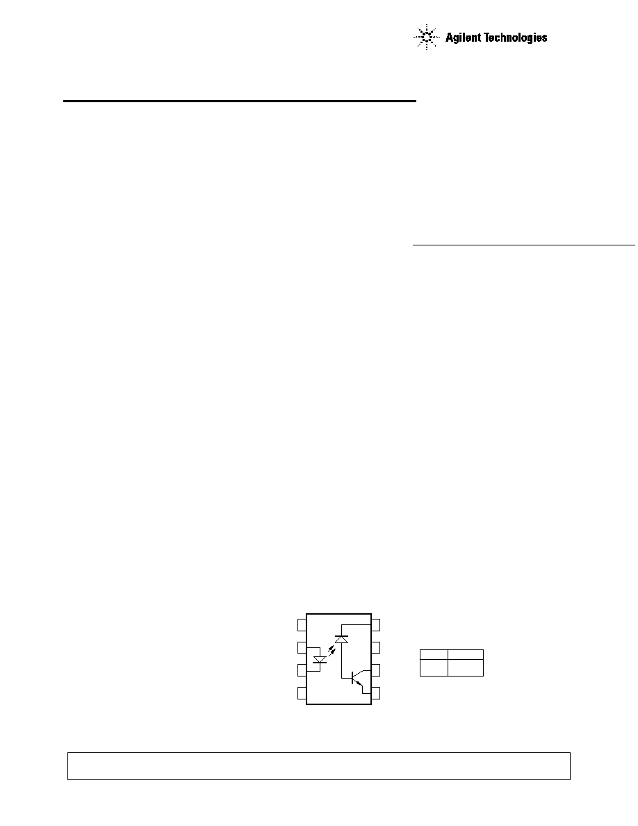
Functional Diagram
CAUTION: It is advised that normal static precautions be taken in handling and assembly of this component to
prevent damage and/or degradation which may be induced by ESD.
A 0.1
µ
F bypass capacitor between pins 5 and 8 is recommended.
7
1
2
3
4
5
6
8
NC
ANODE
CATHODE
NC
VCC
NC
VO
GND
TRUTH TABLE
LED
ON
OFF
VO
LOW
HIGH
Description
The HCPL-4504 and HCPL-0454
contain a GaAsP LED while the
HCPL-J454 and HCNW4504
contain an AlGaAs LED. The LED
is optically coupled to an
integrated high gain photo
detector.
The HCPL-4504 series has short
propagation delays and high CTR.
The HCPL-4504 series also has a
guaranteed propagation delay
difference (t
PLH
-t
PHL
). These
∑ Replaces Pulse
Transformers -
Save Board Space and Weight
∑ Analog Signal Ground
Isolation -
Integrated Photodetector
Provides Improved Linearity
over Phototransistors

2
features make the HCPL-4504
series an excellent solution to IPM
inverter dead time and other
switching problems. The CTR,
propagation delay, and CMR are
specified both for TTL and IPM
conditions which are provided for
ease of application. These single
channel, diode-transistor opto-
couplers are available in 8-Pin
DIP, SO-8, and Widebody
Schematic
Selection Guide
Standard 8-Pin
White Mold 8-Pin
Widebody
Package Type
DIP (300 Mil)
DIP (300 Mil)
Small Outline SO8
(400 Mil)
Part Number
HCPL-4504
HCPL-J454
HCPL-0454
HCNW4504
IEC/EN/DIN EN
V
IORM
= 630 Vpeak
V
IORM
= 891 Vpeak
V
IORM
= 560 Vpeak
V
IORM
= 1414 Vpeak
60747-5-2
(Option 060)
(Option 060)
Approval
Ordering Information
Specify Part number followed by Option Number (if desired)
Example
HCPL-4504 #XXXX
020 = UL 5000 Vrms/1minute Option* for HCPL-4504 Only.
060 = IEC/EN/DIN EN 60747-5-2 Option* for HCPL-4504/0454.
300 = Gull-Wing Lead Option for HCPL-4504/J454, HCNW4504.
500 = Tape and Reel Packaging Option.
XXXE = Lead Free Option
Option data sheets available. Contact Agilent sales representative or authorized distributor for information.
*Combination of Option 020 and Option 060 is not available.
Remarks: The notation "#" is used for existing products, while (new) products launched since 15th July
2001 and lead free option will use "-"
package configurations. An
insulating layer between a LED
and an integrated photodetector
provide electrical insulation
between input and output.
Separate connections for the
photodiode bias and output-
transistor collector increase the
speed up to a hundred times that
of a conventional phototransistor
coupler by reducing the base
collector capacitance.
IF
SHIELD
8
6
5
GND
VCC
2
3
VO
ICC
VF
IO
ANODE
CATHODE
+
≠

3
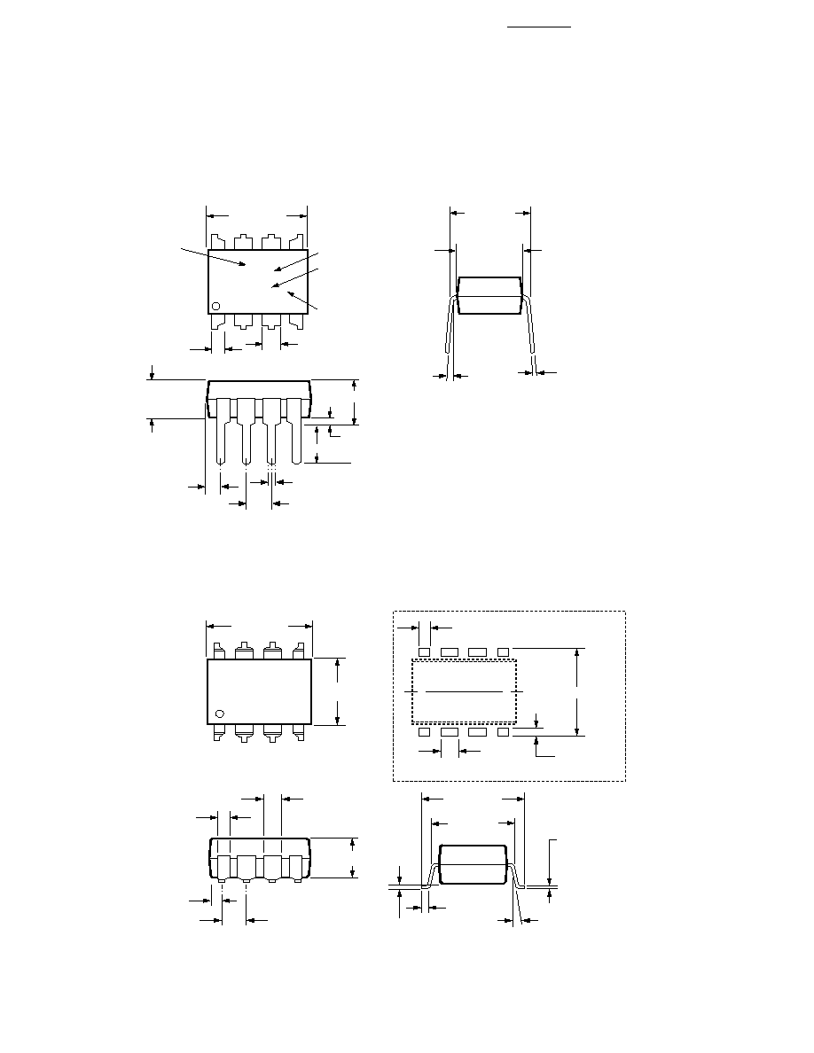
Package Outline Drawings
HCPL-4504 Outline Drawing
HCPL-4504 Gull Wing Surface Mount Option 300 Outline Drawing
1.080 ± 0.320
(0.043 ± 0.013)
2.54 ± 0.25
(0.100 ± 0.010)
0.51 (0.020) MIN.
0.65 (0.025) MAX.
4.70 (0.185) MAX.
2.92 (0.115) MIN.
5∞ TYP.
0.254
+ 0.076
- 0.051
(0.010
+ 0.003)
- 0.002)
7.62 ± 0.25
(0.300 ± 0.010)
6.35 ± 0.25
(0.250 ± 0.010)
9.65 ± 0.25
(0.380 ± 0.010)
1.78 (0.070) MAX.
1.19 (0.047) MAX.
A XXXXZ
YYWW
DATE CODE
DIMENSIONS IN MILLIMETERS AND (INCHES).
5
6
7
8
4
3
2
1
OPTION CODE*
UL
RECOGNITION
UR
TYPE NUMBER
* MARKING CODE LETTER FOR OPTION NUMBERS
"L" = OPTION 020
"V" = OPTION 060
OPTION NUMBERS 300 AND 500 NOT MARKED.
NOTE: FLOATING LEAD PROTRUSION IS 0.25 mm (10 mils) MAX.
3.56 ± 0.13
(0.140 ± 0.005)
0.635 ± 0.25
(0.025 ± 0.010)
12∞ NOM.
9.65 ± 0.25
(0.380 ± 0.010)
0.635 ± 0.130
(0.025 ± 0.005)
7.62 ± 0.25
(0.300 ± 0.010)
5
6
7
8
4
3
2
1
9.65 ± 0.25
(0.380 ± 0.010)
6.350 ± 0.25
(0.250 ± 0.010)
1.016 (0.040)
1.27 (0.050)
10.9 (0.430)
2.0 (0.080)
LAND PATTERN RECOMMENDATION
1.080 ± 0.320
(0.043 ± 0.013)
3.56 ± 0.13
(0.140 ± 0.005)
1.780
(0.070)
MAX.
1.19
(0.047)
MAX.
2.54
(0.100)
BSC
DIMENSIONS IN MILLIMETERS (INCHES).
LEAD COPLANARITY = 0.10 mm (0.004 INCHES).
NOTE: FLOATING LEAD PROTRUSION IS 0.25 mm (10 mils) MAX.
0.254
+ 0.076
- 0.051
(0.010
+ 0.003)
- 0.002)
4
Package Outline Drawings
HCPL-J454 Outline Drawing
HCPL-J454 Gull Wing Surface Mount Option 300 Outline Drawing
1.080 ± 0.320
(0.043 ± 0.013)
2.54 ± 0.25
(0.100 ± 0.010)
0.51 (0.020) MIN.
0.65 (0.025) MAX.
4.70 (0.185) MAX.
2.92 (0.115) MIN.
5∞ TYP.
0.254
+ 0.076
- 0.051
(0.010
+ 0.003)
- 0.002)
7.62 ± 0.25
(0.300 ± 0.010)
6.35 ± 0.25
(0.250 ± 0.010)
9.80 ± 0.25
(0.386 ± 0.010)
1.78 (0.070) MAX.
1.19 (0.047) MAX.
A XXXXZ
YYWW
DATE CODE
DIMENSIONS IN MILLIMETERS AND (INCHES).
5
6
7
8
4
3
2
1
OPTION CODE*
UL
RECOGNITION
UR
TYPE NUMBER
* MARKING CODE LETTER FOR OPTION NUMBERS
"L" = OPTION 020
"V" = OPTION 060
OPTION NUMBERS 300 AND 500 NOT MARKED.
NOTE: FLOATING LEAD PROTRUSION IS 0.5 mm (20 mils) MAX.
3.56 ± 0.13
(0.140 ± 0.005)
0.635 ± 0.25
(0.025 ± 0.010)
12∞ NOM.
9.65 ± 0.25
(0.380 ± 0.010)
0.635 ± 0.130
(0.025 ± 0.005)
7.62 ± 0.25
(0.300 ± 0.010)
5
6
7
8
4
3
2
1
9.80 ± 0.25
(0.386 ± 0.010)
6.350 ± 0.25
(0.250 ± 0.010)
1.016 (0.040)
1.27 (0.050)
10.9 (0.430)
2.0 (0.080)
LAND PATTERN RECOMMENDATION
1.080 ± 0.320
(0.043 ± 0.013)
1.780
(0.070)
MAX.
1.19
(0.047)
MAX.
2.54
(0.100)
BSC
DIMENSIONS IN MILLIMETERS (INCHES).
LEAD COPLANARITY = 0.10 mm (0.004 INCHES).
0.254
+ 0.076
- 0.051
(0.010
+ 0.003)
- 0.002)
NOTE: FLOATING LEAD PROTRUSION IS 0.5 mm (20 mils) MAX.
3.56 ± 0.13
(0.140 ± 0.005)
5
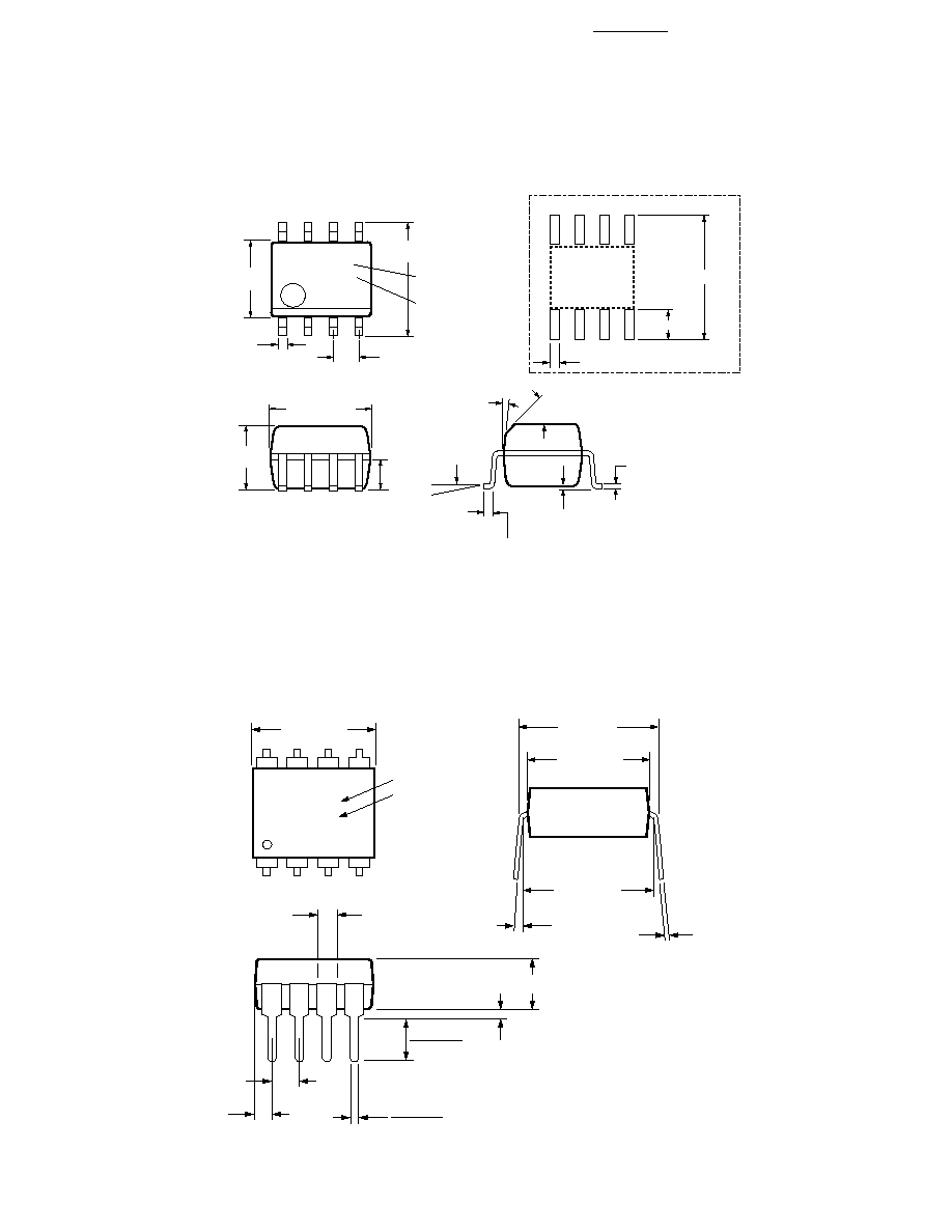
HCPL-0454 Outline Drawing (8-Pin Small Outline Package)
HCNW4504 Outline Drawing (8-Pin Widebody Package)
XXX
YWW
8
7
6
5
4
3
2
1
5.994 ± 0.203
(0.236 ± 0.008)
3.937 ± 0.127
(0.155 ± 0.005)
0.406 ± 0.076
(0.016 ± 0.003)
1.270
(0.050)
BSC
5.080 ± 0.127
(0.200 ± 0.005)
3.175 ± 0.127
(0.125 ± 0.005)
1.524
(0.060)
45∞ X
0.432
(0.017)
0.228 ± 0.025
(0.009 ± 0.001)
TYPE NUMBER
(LAST 3 DIGITS)
DATE CODE
0.305
(0.012)
MIN.
TOTAL PACKAGE LENGTH (INCLUSIVE OF MOLD FLASH)
5.207 ± 0.254 (0.205 ± 0.010)
DIMENSIONS IN MILLIMETERS (INCHES).
LEAD COPLANARITY = 0.10 mm (0.004 INCHES) MAX.
NOTE: FLOATING LEAD PROTRUSION IS 0.15 mm (6 mils) MAX.
0.203 ± 0.102
(0.008 ± 0.004)
7∞
PIN ONE
0 ~ 7∞
*
*
7.49 (0.295)
1.9 (0.075)
0.64 (0.025)
LAND PATTERN RECOMMENDATION
5
6
7
8
4
3
2
1
11.15 ± 0.15
(0.442 ± 0.006)
1.78 ± 0.15
(0.070 ± 0.006)
5.10
(0.201)
MAX.
1.55
(0.061)
MAX.
2.54 (0.100)
TYP.
DIMENSIONS IN MILLIMETERS (INCHES).
NOTE: FLOATING LEAD PROTRUSION IS 0.25 mm (10 mils) MAX.
7∞ TYP.
0.254
+ 0.076
- 0.0051
(0.010
+ 0.003)
- 0.002)
11.00
(0.433)
9.00 ± 0.15
(0.354 ± 0.006)
MAX.
10.16 (0.400)
TYP.
A
HCNWXXXX
YYWW
DATE CODE
TYPE NUMBER
0.51 (0.021) MIN.
0.40 (0.016)
0.56 (0.022)
3.10 (0.122)
3.90 (0.154)