 | –≠–ª–µ–∫—Ç—Ä–æ–Ω–Ω—ã–π –∫–æ–º–ø–æ–Ω–µ–Ω—Ç: HLMA-VL00 | –°–∫–∞—á–∞—Ç—å:  PDF PDF  ZIP ZIP |
Document Outline
- Selection Guide
- List of Figures
- 2a. Forward Current vs. Forward Voltage, HLMA-VL00/VH00.
- 2b. Forward Current vs. Forward Voltage, HLMP-V100.
- 2c. Forward Current vs. Forward Voltage, HLMP-V500.
- 3. Relative Luminous Intensity vs. Forward Current.
- 4a. Relative Efficiency vs. Peak Forward Current, HLMA-VL00/VH00.
- 4b. Relative Efficiency vs. Peak Forward Current, HLMP-V100.
- 4c. Relative Efficiency vs. Peak Forward Current, HLMP-V500.
- 5a. Maximum Forward DC Current vs. Ambient Temperature, HLMA-VL00/VH00.
- 5b. Maximum Forward DC Current vs. Ambient Temperature, HLMP-V100.
- 5c. Maximum Forward DC Current vs. Ambient Temperature, HLMP-V500.
- 6a. Maximum Allowable Average Power vs. Ambient Temperature, HLMA-VL00/VH00.
- 6b. Maximum Allowable Average Power vs. Ambient Temperature, HLMP-V100.
- 6c. Maximum Allowable Average Power vs. Ambient Temperature, HLMP-V500.
- 7a. Relative Intensity vs. Angle, HLMA-VL00/VH00 Horizontal Axis.
- 7b. Relative Intensity vs. Angle, HLMA-VL00/VH00 Vertical Axis.
- 8a. Relative Intensity vs. Angle, HLMP-V100 Horizontal Axis.
- 8b. Relative Intensity vs. Angle, HLMP-V100 Vertical Axis.
- 9a. Relative Intensity vs. Angle, HLMP-V500 Horizontal Axis.
- 9b. Relative Intensity vs. Angle, HLMP-V500 Vertical Axis.
- Features
- Description
- Applications
- Outline Drawing
- Device Selection Guide
- Absolute Maximum Ratings at T A = 25∞C
- Optical Characteristics at T A = 25∞C
- Electrical Characteristics at T A = 25∞C

1-56
T-13/4 (5 mm), Wide Viewing
Angle, High Intensity LED
Lamps
Technical Data
Features
∑ Outstanding LED Material
Efficiency
∑ Extremely Wide Horizontal
Viewing Angle
∑ High Light Output over a
Wide Range of Currents
∑ Untinted, Non-diffused Lens
∑ Choice of Four Colors: 644
nm Red, 590 nm Amber, 570
nm Green, and 615 nm
Orange
H
Description
These high intensity LED lamps
provide the user with an
extremely wide 60
∞
(horizontal)
by 30
∞
(vertical) oval shaped
radiation pattern. Available in TS
AlGaAs red, AlInGaP amber,
AlInGaP orange, and GaP green
colors, these untinted non-
diffused T-1
3
/
4
(5 mm) LEDs are
an excellent choice for outdoor
applications requiring an
extremely wide field of vision and
high brightness.
Applications
∑ Outdoor Message Boards
∑ Safety Lighting Equipment
∑ Changeable Message Signs
∑ Alternative to Incandescent
Lamps
Device Selection Guide
Amber
Red-Orange
Red
Green
d
= 590 nm
d
= 615 nm
d
= 644 nm
d
= 570 nm
HLMA-VL00
HLMA-VH00
HLMP-V100
HLMP-V500
Outline Drawing
13.97
±
0.76
(0.550
±
0.030)
NOTE 1
1.02
(0.040)
MAX
0.51
(0.020)
SQUARE
NOMINAL
2.54
±
0.25
(0.100
±
0.010)
2.54
±
0.25
(0.100
±
0.010)
2.54
±
.025
(0.100
±
0.010)
8.71
±
0.38
(0.343
±
0.015)
MIN
20.32
(0.800)
5.59
±
0.25
(0.220
±
0.010)
5.08
±
0.25
(0.200
±
0.010)
HLMA-VL00
HLMP-V100
HLMP-V500
HLMA-VH00
NOTES:
1. LEAD ORIENTATION:
DEVICE TYPE
HLMP-V100
HLMP-V500
HLMA-VL00
HLMA-VH00
2. ALL DIMENSIONS ARE IN MM (INCHES).
CENTER LEAD
COMMON ANODE
COMMON CATHODE
COMMON CATHODE
COMMON CATHODE
OUTER LEADS
CATHODE
ANODE
ANODE
ANODE
2.54 ± 0.76
(0.100 ± 0.030)
5964-9292E

1-57
Absolute Maximum Ratings at T
A
= 25
∞
C
Parameter
HLMA-VL00
HLMA-VH00
HLMP-V100
HLMP-V500
Units
DC Forward Current
[1,3]
60
[4,5]
60
[4,5]
60
50
mA
Peak Forward Current
[2,3]
400
400
600
180
mA
Average Input Power
[2]
120
120
120
110
mW
Reverse Voltage (I
R
= 200
µ
A)
5
5
5
5
V
Operating Temperature Range
-40 to +100
-40 to +100
-55 to +85
-20 to +100
∞
C
Storage Temperature Range
-55 to +100
-55 to +100
-55 to +100
-55 to +100
∞
C
Junction Temperature
110
∞
C
Soldering Temperature
260
∞
C for 5 seconds
[1.59 mm (0.06 in.) below
seating plane]
Notes:
1. Derate linearly as shown in Figure 5.
2. Any pulsed operation cannot exceed the Absolute Max Peak Forward Current or the Max Allowable Average Power as specified in
Figure 6.
3. Specified with both die powered simultaneously.
4. Drive Currents between 10 mA and 30 mA are recommended for best long term performance.
5. Operation at currents below 10 mA is not recommended, please contact your Hewlett-Packard sales representative.
Forward
Reverse
Capacitance
Speed of Response
Voltage
Breakdown
C (pF)
Thermal
s
(ns)
V
F
(Volts)
V
R
(Volts)
V
F
= 0,
Resistance
Time Constant
@ I
F
= 40 mA
@ I
R
= 200
µ
A
f = 1 MHz
R
J-PIN
e
-t/
s
Part Number
Typ.
Max.
Min.
Typ.
(
∞
C/W)
Typ.
HLMA-VL00
1.90
2.4
5
120
100
13
HLMA-VH00
1.90
2.4
5
120
100
13
HLMP-V100
1.85
2.4
5
50
115
26
HLMP-V500
2.20
3.0
5
20
100
171
Electrical Characteristics at T
A
= 25
∞
C
Luminous
Color,
Viewing
Intensity
Peak
Dominant
Angle
Luminous
I
V
(mcd)
Wavelength
Wavelength
2
1
/
2
Efficacy
@ 40 mA
[1]
peak
(nm)
d
[2]
(nm)
Degrees
[3]
V
Part Number
Min.
Typ.
Typ.
Typ.
Typ.
(lm/w)
HLMA-VL00
212
460
592
590
60
∞
horizontal
480
30
∞
vertical
HLMA-VH00
200
460
621
615
263
HLMP-V100
500
1000
654
644
60
∞
horizontal
85
30
∞
vertical
HLMP-V500
112
270
568
570
60
∞
horizontal
595
30
∞
vertical
Notes:
1. The luminous intensity, I
V
, is measured at the mechanical axis of the lamp package. The actual peak of the spatial radiation pattern
may not be aligned with this axis.
2. The dominant wavelength,
d
, is derived from the CIE Chromaticity Diagram and represents the color of the device.
3. 2
1/2
is the off-axis angle where the luminous intensity is 1/2 the on-axis intensity.
Optical Characteristics at T
A
= 25
∞
C

1-58
Figure 2a. Forward Current vs.
Forward Voltage, HLMA-VL00/VH00.
Figure 4c. Relative Efficiency vs. Peak
Forward Current, HLMP-V500.
Figure 5b. Maximum Forward DC
Current vs. Ambient Temperature,
HLMP-V100.
Figure 2b. Forward Current vs.
Forward Voltage, HLMP-V100.
Figure 2c. Forward Current vs.
Forward Voltage, HLMP-V500.
50
40
30
20
10
0
0
20
40
60
80
100
T
A
≠ AMBIENT TEMPERATURE ≠
∞
C
I
F
≠ FORWARD CURRENT ≠ mA
(BOTH DIE POWERED SIMULTANEOUSLY)
60
70
R
JA
= 350
∞
C/W
R
JA
= 480
∞
C/W
50
40
30
20
10
0
0
20
40
60
80
100
T
A
≠ AMBIENT TEMPERATURE ≠
∞
C
I
F
≠ FORWARD CURRENT ≠ mA
(BOTH DIE POWERED SIMULTANEOUSLY)
60
70
85
R
JA
= 350
∞
C/W
R
JA
= 480
∞
C/W
PEAK
≠ RELATIVE EFFICIENCY
(NORMALIZED AT 40 mA)
1.3
0.4
I
PEAK
≠ PEAK FORWARD CURRENT ≠ mA
1.2
1.0
0.9
1.1
0.6
0
180
60
120
20
100
140
40
80
160
0.5
0.7
0.8
40
0.6
10
I
F
≠ FORWARD CURRENT ≠ mA
0
0.2
20
30
0.8
0.4
1.0
RELATIVE LUMINOUS INTENSITY
50
RED
ORANGE & AMBER
60
1.2
1.4
1.6
GREEN
1.2
1.1
1.0
0.9
0.0
1
4
10
20
40
100
200
400 600
0.8
0.7
0.6
0.5
0.4
0.3
0.2
0.1
I
PEAK
≠ PEAK FORWARD CURRENT ≠ mA
1.3
V
≠ RELATIVE EFFICIENCY
(NORMALIZED AT 40 mA)
I F
≠ FORWARD CURRENT ≠ mA
1.0
0
VF ≠ FORWARD VOLTAGE ≠ V
2.5
400
240
160
1.5
2.0
320
3.0
80
40
120
200
280
360
I
F
≠ FORWARD CURRENT ≠ mA
(BOTH DIE POWERED SIMULTANEOUSLY)
1.7
2.6
1
V
F
≠ FORWARD VOLTAGE ≠ V
1.9
2.2
2.0
2.4
200
100
10
2.8
3.0
3.2
I
F
≠ FORWARD CURRENT ≠ mA
(BOTH DIE POWERED SIMULTANEOUSLY)
1.5
4.0
600
1
V
F
≠ FORWARD VOLTAGE ≠ V
2.0
3.0
2.5
3.5
200
100
10
4.5
V
≠ RELATIVE EFFICIENCY
(NORMALIZED AT 40 mA)
2.6
0
I
PEAK
≠ PEAK FORWARD CURRENT ≠ mA
2.4
1.8
1.4
2.0
0.6
0
400
120
240
40
200
280
80
160
320
0.2
0.8
1.2
2.2
1.6
1.0
0.4
360
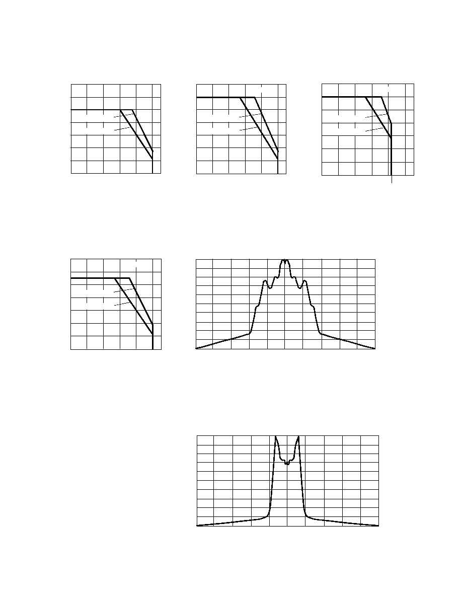
Figure 5a. Maximum Forward DC
Current vs. Ambient Temperature,
HLMA-VL00/VH00.
Figure 4b. Relative Efficiency vs. Peak
Forward Current, HLMP-V100.
Figure 3. Relative Luminous Intensity
vs. Forward Current.
Figure 4a. Relative Efficiency vs. Peak
Forward Current, HLMA-VL00/VH00.
1-59
Figure 7b. Relative Intensity vs. Angle, HLMA-VL00/VH00 Vertical Axis.
ANGULAR DISPLACEMENT (DEGREES)
NORMALIZED LUMINOUS INTENSITY
1.0
0.9
0.8
0.7
0.6
0.5
0.4
0.3
0.2
0.1
0
80
60
0
-20
-40
-60
-80
-100
100
40
20
50
40
30
20
10
0
0
20
40
60
80
100
T
A
≠ AMBIENT TEMPERATURE ≠
∞
C
I
F
≠ FORWARD CURRENT ≠ mA
(BOTH DIE POWERED SIMULTANEOUSLY)
60
70
R
JA
= 350
∞
C/W
R
JA
= 480
∞
C/W
100
80
60
40
20
0
0
20
40
60
80
100
T
A
≠ AMBIENT TEMPERATURE ≠
∞
C
TIME AVERAGE POWER (mW)
(BOTH DIE POWERED SIMULTANEOUSLY)
120
140
R
JA
= 350
∞
C/W
R
JA
= 480
∞
C/W
f
100 Hz
100
80
60
40
20
0
0
20
40
60
80
100
T
A
≠ AMBIENT TEMPERATURE ≠
∞
C
TIME AVERAGE POWER (mW)
(BOTH DIE POWERED SIMULTANEOUSLY)
120
140
85
R
JA
= 350
∞
C/W
R
JA
= 480
∞
C/W
f
100 Hz
Figure 6a. Maximum Allowable
Average Power vs. Ambient
Temperature, HLMA-VL00/VH00.
Figure 6b. Maximum Allowable
Average Power vs. Ambient
Temperature, HLMP-V100.
Figure 5c. Maximum Forward DC
Current vs. Ambient Temperature,
HLMP-V500.
100
80
60
40
20
0
0
20
40
60
80
100
T
A
≠ AMBIENT TEMPERATURE ≠
∞
C
TIME AVERAGE POWER (mW)
(BOTH DIE POWERED SIMULTANEOUSLY)
120
140
R
JA
= 350
∞
C/W
R
JA
= 480
∞
C/W
f
100 Hz
ANGULAR DISPLACEMENT (DEGREES)
NORMALIZED LUMINOUS INTENSITY
1.0
0.9
0.8
0.7
0.6
0.5
0.4
0.3
0.2
0.1
0
80
60
0
-20
-40
-60
-80
-100
100
40
20
Figure 6c. Maximum Allowable
Average Power vs. Ambient
Temperature, HLMP-V500.
Figure 7a. Relative Intensity vs. Angle, HLMA-VL00/VH00 Horizontal Axis.

1-60
Figure 8a. Relative Intensity vs. Angle, HLMP-V100 Horizontal Axis.
Figure 9a. Relative Intensity vs. Angle, HLMP-V500 Horizontal Axis.
Figure 8b. Relative Intensity vs. Angle, HLMP-V100 Vertical Axis.
ANGULAR DISPLACEMENT (DEGREES)
NORMALIZED LUMINOUS INTENSITY
1.0
0.9
0.8
0.7
0.6
0.5
0.4
0.3
0.2
0.1
0
80
60
0
-20
-40
-60
-80
-100
100
40
20
ANGULAR DISPLACEMENT (DEGREES)
NORMALIZED LUMINOUS INTENSITY
1.0
0.9
0.8
0.7
0.6
0.5
0.4
0.3
0.2
0.1
0
80
60
0
-20
-40
-60
-80
-100
100
40
20
ANGULAR DISPLACEMENT (DEGREES)
NORMALIZED LUMINOUS INTENSITY
1.0
0.9
0.8
0.7
0.6
0.5
0.4
0.3
0.2
0.1
0
80
60
0
-20
-40
-60
-80
-100
100
40
20