LED Light Bars
Technical Data
Features
∑ Large Bright, Uniform Light
Emitting Areas
∑ Choice of Colors
∑ Categorized for Light Output
∑ Yellow and Green
Categorized for Dominant
Wavelength
∑ Excellent ON-OFF Contrast
∑ X-Y Stackable
∑ Flush Mountable
∑ Can be Used with Panel and
Legend Mounts
∑ Light Emitting Surface
Suitable for Legend
Attachment per Application
Note 1012
∑ HLCP-X100 Series Designed
for Low Current Operation
∑ Bicolor Devices Available
Applications
∑ Business Machine
Message Annunciators
∑ Telecommunications
Indicators
∑ Front Panel Process Status
Indicators
∑ PC Board Identifiers
∑ Bar Graphs
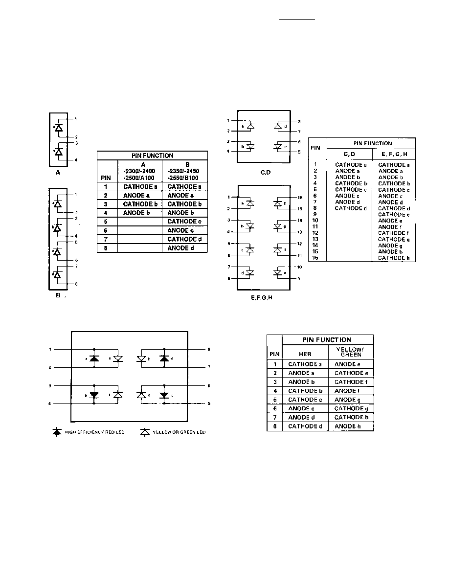
Description
The HLCP-X100 and HLMP-2XXX
series light bars are rectangular
light sources designed for a
variety of applications where a
large bright source of light is
required. These light bars are
configured in single-in-line and
dual-in-line packages that contain
either single or segmented light
emitting areas. The AlGaAs Red
HLCP-X100 series LEDs use
double heterojunction AlGaAs on
a GaAs substrate. The HER
HLMP-2300/2600 and Yellow
HLMP-2400/2700 series LEDs
have their p-n junctions diffused
into a GaAsP epitaxial layer on a
GaP substrate. The Green HLMP-
2500/2800 series LEDs use a
liquid phase GaP epitaxial layer
on a GaP substrate. The bicolor
HLMP-2900 series use a
combination of HER/Yellow or
HER/Green LEDs.
HLCP-A100, -B100, -C100,
-D100, -E100, -F100, -G100,
-H100
HLMP-2300, -2350, -2400,
-2450, -2500, -2550, -2600,
-2620, -2635, -2655, -2670,
-2685, -2700, -2720, -2735,
-2755, -2770, -2785, -2800,
-2820, -2835, -2855, -2870,
-2885, -2950, -2965
3
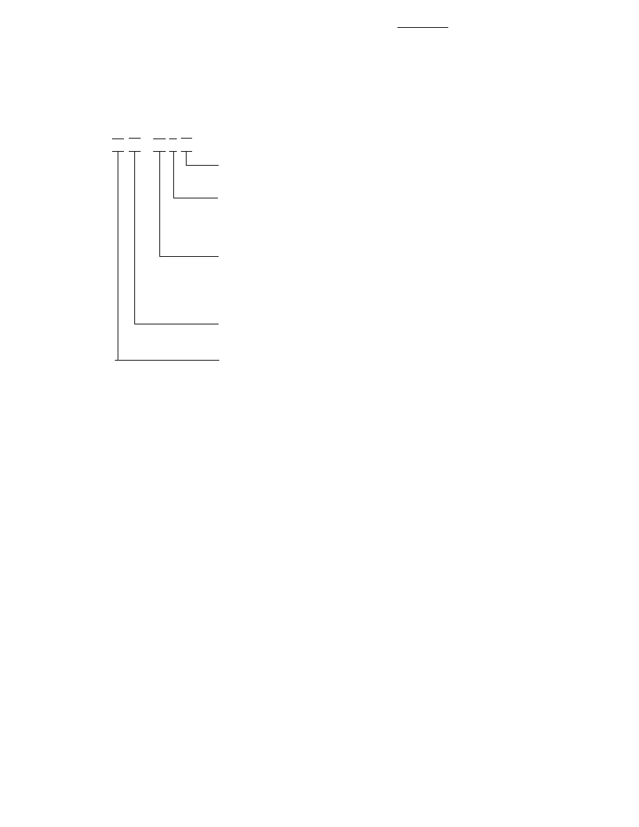
Part Numbering System
HLCP - xx xx - xx x xx
HLMP - xx xx - xx x xx
Mechanical Options
[1]
00: No mechanical option
Color Bin Options
[1,2]
0: No color bin limitation
B: Color bins 2 & 3 (applicable for yellow devices only)
C: Color bins 3 & 4 only (applicable for green devices only)
Maximum Intensity Bin
[1,2]
0: No maximum intensity bin limitation
Minimum Intensity Bin
[1,2]
0: No minimum intensity bin limitation
Device Specific Configuration
[1]
Refer to respective data sheet
Color
[1]
x1: AlGaAs Red (applicable for HLCP-x100 only)
23: High Efficiency Red
24: Yellow
25: Green
26: High Efficiency Red
27: Yellow
28: Green
29: Bicolor (High Efficiency Red/Yellow) OR (High Efficiency Red/Green)
Notes:
1. For codes not listed in the figure above, please refer to the respective data sheet or contact your nearest Agilent representative
for details.
2. Bin options refer to shippable bins for a part-number. Color and Intensity Bins are typically restricted to 1 bin per tube
(exceptions may apply). Please refer to respective data sheet for specific bin limit information.