 | –≠–ª–µ–∫—Ç—Ä–æ–Ω–Ω—ã–π –∫–æ–º–ø–æ–Ω–µ–Ω—Ç: HLMP-8605 | –°–∫–∞—á–∞—Ç—å:  PDF PDF  ZIP ZIP |
H
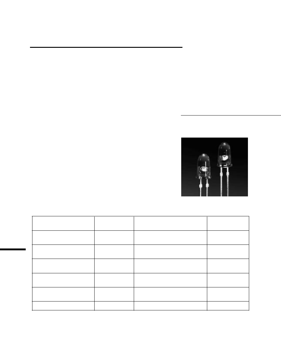
T-1
3
/
4
Super Ultra-Bright
LED Lamps
Technical Data
Features
∑ Very High Intensity
∑ Narrow and Medium Viewing
Angles
∑ Untinted, Nondiffused Lens
∑ Choice of Five Colors
∑ Sturdy Leads with Seating
Plane Tabs
Description
These untinted, nondiffused solid
state lamps are designed with
special internal optics to give a
very high luminous intensity
within a well defined viewing
angle. The LED materials used
within these devices is specifically
grown to assure the high light
output performance these lamps
provide.
Device Selection Guide
Typical Luminous Intensity
2
1
/
2
LED Color
Part Number
(mcd @ 20 mA dc)
Viewing Angle
DH AS AlGaAs
HLMP-8115
1000
10
∞
HLMP-8109
500
20
∞
High Efficiency Red
HLMP-8205
350
10
∞
HLMP-8209
260
20
∞
Yellow
HLMP-8305
350
10
∞
HLMP-8309
260
20
∞
Orange
HLMP-8405
350
10
∞
HLMP-8409
260
20
∞
High Performance Green
HLMP-8505
400
10
∞
HLMP-8509
300
20
∞
Emerald Green
HLMP-8605
75
10
∞
HLMP-8115 HLMP-8109
HLMP-8205 HLMP-8209
HLMP-8305 HLMP-8309
HLMP-8405 HLMP-8409
HLMP-8505 HLMP-8509
HLMP-8605

2
Notes:
1. See Figure 5 for maximum current derating vs. ambient temperature.
2. See Figure 6 for maximum peak current vs. pulse duration and allowable duty factor.
3. The transient peak current is the maximum non-recurring peak current the device can withstand without damaging the LED die and
wire bond. Do not operate these lamps at peak currents above the Absolute Maximum Peak Forward Current.
Absolute Maximum Ratings at T
A
= 25
∞
C
DH AS
High
High
AlGaAs
Efficiency Red
Performance
Parameter
Red
and Orange
Yellow
Green/Emerald Green
Units
DC Forward Current
[1]
30
30
20
30
mA
Peak Forward Current
[2]
300
90
60
90
mA
Average Forward Current
[2]
20
25
20
25
mA
Transient Forward Current
[3]
(10
µ
s Pulse)
500
500
500
500
mA
Reverse Voltage (I
R
= 100
µ
A)
5
5
5
5
V
LED Junction Temperature
110
110
110
110
∞
C
Operating Temperature Range
-20 to +100
-55 to +100
-20 to +100
∞
C
Storage Temperature Range
-55 to +100
∞
C
Lead Soldering Temperature
260
∞
C for 5 seconds
[1.6 mm (0.063 in.) from body]
Package Dimensions

3
Electrical/Optical Characteristics T
A
= 25
∞
C
DH AS AlGaAs HLMP-8115/8109
Parameter
Symbol
Min.
Typ.
Max.
Units
Test Conditions
Luminous Intensity
HLMP-8115
I
v
500
1000
mcd
I
F
= 20 mA
HLMP-8109
200
500
Forward Voltage
V
F
1.8
2.2
V
I
F
= 20 mA
Reverse Breakdown Voltage
V
R
5.0
15.0
V
I
R
= 100
µ
A
Included Angle Between
Half Intensity Points
HLMP-8115
2
1/2
10
Deg.
HLMP-8109
20
Total Luminous Flux
d
120
mlm
I
F
= 20 mA
Peak Wavelength
PEAK
645
nm
Measured at Peak
Dominant Wavelength
[1]
d
637
nm
Spectral Line Half Width
1/2
20
nm
Speed of Response
s
30
ns
Time Constant, e
-t/
Capacitance
C
30
pF
V
F
= 0, f = 1 MHz
Thermal Resistance
R
J-LEAD
210
∞
C/W
LED Junction-to-
Cathode Lead
Luminous Efficacy
[2]
v
80
lm/W
High Efficiency Red HLMP-8205/8209
Parameter
Symbol
Min.
Typ.
Max.
Units
Test Conditions
Luminous Intensity
HLMP-8205
I
v
200
350
mcd
I
F
= 20 mA
HLMP-8209
90
260
Forward Voltage
V
F
1.9
2.6
V
I
F
= 20 mA
Reverse Breakdown Voltage
V
R
5.0
30.0
V
I
R
= 100
µ
A
Included Angle Between
Half Intensity Points
HLMP-8205
2
1/2
10
Deg.
HLMP-8209
20
Total Luminous Flux
v
45
mlm
I
F
= 20 mA
Peak Wavelength
PEAK
635
nm
Measured at Peak
Dominant Wavelength
[1]
d
626
nm
Spectral Line Half Width
1/2
40
nm
Speed of Response
s
90
ns
Capacitance
C
11
pF
V
F
= 0, f = 1 MHz
Thermal Resistance
R
J-LEAD
210
∞
C/W
LED Junction-to-
Cathode Lead
Luminous Efficacy
[2]
v
145
lm/W
s

4
Yellow HLMP-8305/8309
Parameter
Symbol
Min.
Typ.
Max.
Units
Test Conditions
Luminous Intensity
HLMP-8305
I
v
212
350
mcd
I
F
= 20 mA
HLMP-8309
96
260
Forward Voltage
V
F
2.1
2.6
V
I
F
= 20 mA
Reverse Breakdown Voltage
V
R
5.0
30.0
V
I
R
= 100
µ
A
Included Angle Between
Half Intensity Points
HLMP-8305
2
1/2
10
Deg.
HLMP-8309
20
Total Luminous Flux
v
45
mlm
I
F
= 20 mA
Peak Wavelength
PEAK
583
nm
Measured at Peak
Dominant Wavelength
[1]
d
585
nm
Spectral Line Half Width
1/2
36
nm
Speed of Response
s
90
ns
Capacitance
C
15
pF
V
F
= 0, f = 1 MHz
Thermal Resistance
R
J-LEAD
210
∞
C/W
LED Junction-to-
Cathode Lead
Luminous Efficacy
[2]
v
500
lm/W
Orange HLMP-8405/8409
Parameter
Symbol
Min.
Typ.
Max.
Units
Test Conditions
Luminous Intensity
HLMP-8405
I
v
200
350
mcd
I
F
= 20 mA
HLMP-8409
90
260
Forward Voltage
V
F
1.9
2.6
V
I
F
= 20 mA
Reverse Breakdown Voltage
V
R
5.0
30.0
V
I
R
= 100
µ
A
Included Angle Between
Half Intensity Points
HLMP-8405
2
1/2
10
Deg.
HLMP-8409
20
Total Luminous Flux
v
45
mlm
I
F
= 20 mA
Peak Wavelength
PEAK
600
nm
Measured at Peak
Dominant Wavelength
[1]
d
602
nm
Spectral Line Half Width
1/2
40
nm
Speed of Response
s
280
ns
Capacitance
C
4
pF
V
F
= 0, f = 1 MHz
Thermal Resistance
R
J-LEAD
210
∞
C/W
LED Junction-to-
Cathode Lead
Luminous Efficacy
[2]
v
380
lm/W

5
High Performance Green HLMP-8505/8509
Parameter
Symbol
Min.
Typ.
Max.
Units
Test Conditions
Luminous Intensity
HLMP-8505
I
v
170
400
mcd
I
F
= 20 mA
HLMP-8509
111
300
Forward Voltage
V
F
2.2
3.0
V
I
F
= 20 mA
Reverse Breakdown Voltage
V
R
5.0
30
V
I
R
= 100
µ
A
Included Angle Between
Half Intensity Points
HLMP-8505
2
1/2
10
Deg.
HLMP-8509
20
Total Luminous Flux
v
115
mlm
I
F
= 20 mA
Peak Wavelength
PEAK
568
nm
Measured at Peak
Dominant Wavelength
[1]
d
570
nm
Spectral Line Half Width
1/2
28
nm
Speed of Response
s
260
ns
Capacitance
C
18
pF
V
F
= 0, f = 1 MHz
Thermal Resistance
R
J-LEAD
210
∞
C/W
LED Junction-to-
Cathode Lead
Luminous Efficacy
[2]
v
595
lm/W
Notes:
1. The dominant wavelength,
d
, is derived from the CIE Chromaticity Diagram and represents the color of the device.
2. The radiant intensity, I
e
, in watts per steradian, may be found from the equation I
e
= I
v
/
v
, where I
v
is the luminous intensity in
candelas and
v
is the luminous efficacy in lumens/watt.
Emerald Green HLMP-8605
[1]
Parameter
Symbol
Min.
Typ.
Max.
Units
Test Conditions
Luminous Intensity
HLMP-8605
I
v
69
75
mcd
I
F
= 20 mA
Forward Voltage
V
F
2.2
3.0
V
I
F
= 20 mA
Reverse Breakdown Voltage
V
R
5.0
30
V
I
R
= 100
µ
A
Included Angle Between
Half Intensity Points
HLMP-8605
2
1/2
10
Deg.
Peak Wavelength
PEAK
558
nm
Measured at Peak
Dominant Wavelength
[2]
d
560
nm
Spectral Line Half Width
1/2
24
nm
Speed of Response
s
3100
ns
Capacitance
C
35
pF
V
F
= 0, f = 1 MHz
Thermal Resistance
R
J-LEAD
210
∞
C/W
LED Junction-to-
Cathode Lead
Luminous Efficacy
[3]
v
656
lm/W
Notes:
1. Please refer to Application Note 1061 for information comparing standard green and emerald green light output degradation.
2. The dominant wavelength,
d
, is derived from the CIE Chromaticity Diagram and represents the color of the device.
3. The radiant intensity, I
e
, in watts per steradian, may be found from the equation I
e
= I
v
/
v
, where I
v
is the luminous intensity in
candelas and
v
is the luminous efficacy in lumens/watt.