Agilent HLMP-CE15, HLMP-CE16,
HLMP-CE23, HLMP-CE24,
HLMP-CE30, HLMP-CE31
T-1 3/4 (5 mm) Precision
Optical Performance
InGaN Bluish-Green LED Lamps
Data Sheet
Description
These high intensity bluish-green
LEDs are based on InGaN material
technology. InGaN is the most
efficient and cost effective material
for LEDs in the blue and green
region of the spectrum. The 505 nm
typical dominant wavelength
matches international specifications
for green traffic signals.
These LED lamps are untinted,
nondiffused, T-1 3/4 packages
incorporating second generation
optics producing well defined
spatial radiation patterns at specific
viewing cone angles.
These lamps are made with an
advanced optical grade epoxy,
offering superior temperature and
moisture resistance in outdoor
signal and sign applications. The
package epoxy contains both UV-a
and UV-b inhibitors to reduce the
effects of long term exposure to
direct sunlight.
These lamps are available in three
viewing angle options and two
package options to give the
designer flexibility with optical
design and device mounting.
CAUTION: HLMP-CExx LEDs are Class 1 ESD sensitive. Please observe appropriate precautions during handling
and processing. Refer to Agilent Application Note AN-1142 for additional details.
Features
∑ Smooth, consistent spatial
radiation patterns
∑ High luminous output
∑ Viewing angles 15∞, 23∞, and 30∞
∑ Superior resistance to moisture
Benefits
∑ Viewing angles match traffic
signal requirements
∑ Superior performance in outdoor
environments
∑ Suitable for autoinsertion onto
PC boards
Applications
∑ Traffic signals
∑ Railroad signals
∑ Commercial outdoor signs
∑ Automotive interior lights
2
Device Selection Guide
Color and Dominant
Luminous Intensity I
V
Wavelength
d
Viewing Angle
(mcd) at 20 mA
Part Number
Typ. (nm)
2
1/2
Typ. (deg)
Min.
Max.
Stand-Off
HLMP-CE15-TWCxx
505
15
2500
7200
No
HLMP-CE16-TWCxx
505
15
2500
7200
Yes
HLMP-CE23-SVCxx
505
23
1900
5500
No
HLMP-CE23-SVQxx
505
23
1900
5500
No
HLMP-CE24-SVCxx
505
23
1900
5500
Yes
HLMP-CE24-SVQxx
505
23
1900
5500
Yes
HLMP-CE30-QTCxx
505
30
1150
3200
No
HLMP-CE30-QTQxx
505
30
1150
3200
No
HLMP-CE31-QTCxx
505
30
1150
3200
Yes
HLMP-CE31-QTQxx
505
30
1150
3200
Yes
HLMP-CE23-P0Cxx
505
23
880
-
No
HLMP-CE23-TVQxx
505
23
2500
5500
No
HLMP-CE24-TVQxx
505
23
2500
5500
Yes
HLMP-CE30-N00xx
505
30
680
-
No
HLMP-CE30-RUQxx
505
30
1500
4200
No
HLMP-CE31-N00xx
505
30
680
-
Yes
HLMP-CE31-RUQxx
505
30
1500
4200
Yes
Notes:
1. The luminous intensity is measured on the mechanical axis of the lamp package.
2. The optical axis is closely aligned with the package mechanical axis.
3. The dominant wavelength,
d
, is derived from the CIE Chromaticity Diagram and represents the perceived color of the device.
4. All InGaN LEDs represented here are IEC825 Class 2. See Application Brief 1-009 and 1-015 for details.
5. Tolerance for intensity limit is
±
15%.
Part Numbering System
HLMP - X X X X - X X X X X
Mechanical Options
00: Bulk Packaging
DD: Ammo Pack
Color Bin Selections
C: Color Bins 3 and 4 only
Q: Color Bins 7 and 8 only
Maximum Intensity Bin
0: No Iv Bin Limitation
Minimum Intensity Bin
Viewing Angle and Stand-Off
15: 15 deg, without stand-off
16: 15 deg, with stand-off
23: 23 deg, without stand-off
24: 23 deg, with stand-off
30: 30 deg, without stand-off
31: 30 deg, with stand-off
Color
E: 505 nm Bluish-Green
Package
C: 5 mm InGaN

3
1.14 ± 0.20
(0.045 ± 0.008)
5.80 ± 0.20
(0.228 ± 0.008)
5.00 ± 0.20
(0.197 ± 0.008)
31.60
(1.244)
MIN.
0.70 (0.028)
MAX.
1.00
(0.039)
MIN.
8.71 ± 0.20
(0.343 ± 0.008)
2.54 ± 0.38
(0.100 ± 0.015)
0.50 ± 0.10
(0.020 ± 0.004)
SQ. TYP.
CATHODE
LEAD
CATHODE
FLAT
d
1.50 ± 0.15
(0.059 ± 0.006)
HLMP-CE16, HLMP-CE24, and HLMP-CE31
HLMP-CE24
HLMP-CE31
d = 12.40 ± 0.25
(0.488 ± 0.010)
d = 12.22 ± 0.50
(0.481 ± 0.020)
HLMP-CE16
d = 12.6 ± 0.18
(0.496 ± 0.007)
Package Dimensions
Notes:
1. Dimensions in mm.
2. Tolerance
±
0.1 mm unless otherwise noted.
1.14 ± 0.20
(0.045 ± 0.008)
5.80 ± 0.20
(0.228 ± 0.008)
5.00 ± 0.20
(0.197 ± 0.008)
31.60
(1.244)
MIN.
0.70 (0.028)
MAX.
1.00
(0.039)
MIN.
8.71 ± 0.20
(0.343 ± 0.008)
2.54 ± 0.38
(0.100 ± 0.015)
0.50 ± 0.10
(0.020 ± 0.004)
SQ. TYP.
CATHODE
LEAD
2.35 (0.093)
MAX.
CATHODE
FLAT
HLMP-CE15, HLMP-CE23, and HLMP-CE30
Absolute Maximum Ratings at T
A
= 25∞C
Parameter
Value
Units
DC Forward Current
[1]
30
mA
Peak Forward Current
100
mA
Average Forward Current
30
mA
Power Dissipation
120
mW
Reverse Voltage (I
R
= 100
µ
A)
5
V
LED Junction Temperature
130
∞C
Operating Temperature Range
≠40 to +80
∞C
Storage Temperature Range
≠40 to +100
∞C
Note:
1. Derate linearly as shown in Figure 4 for temperatures above 50∞C.
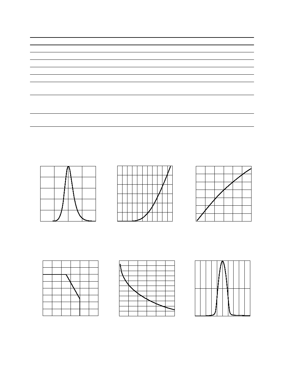
Figure 4. Maximum forward current vs.
ambient temperature.
Figure 5. Color vs. forward current.
Figure 6. Spatial radiation pattern ≠ 15
∞
lamps.
FORWARD CURRENT ≠ mA
0
0
AMBIENT TEMPERATURE ≠ ∞C
40
80
35
30
25
15
10
20
60
100
120
5
20
40
DOMINANT WAVELENGTH ≠ nm
0
498
FORWARD CURRENT ≠ mA
15
25
520
506
10
20
512
30
5
502
508
500
504
510
514
516
518
RELATIVE INTENSITY
1.0
0
ANGLE ≠ DEGREES
0.5
-30
0
30
50
-50
10
-20 -10
20
-40
40
Notes:
1. The dominant wavelength,
d
, is derived from the CIE Chromaticity Diagram and represents the perceived color of the device.
2. The radiant intensity, le in watts per steradian, may be found from the equation le = Iv/
V,
where Iv is the luminous intensity in candelas and
V
is the luminous efficacy in lumens/watt.
Electrical/Optical Characteristics at T
A
= 25∞C
Parameter
Symbol
Min.
Typ.
Max.
Units
Test Conditions
Forward Voltage
V
F
3.8
4.0
V
I
F
= 20 mA
Reverse Voltage
V
R
10
I
R
= 100
µ
A
Capacitance
C
40
pF
V
F
= 0, f = 1 MHz
Thermal Resistance
R
J-PIN
240
∞
C/W
LED Junction-to-Cathode Lead
Dominant Wavelength
d
505
nm
I
F
= 20 mA
Peak Wavelength
PEAK
502
nm
Peak of Wavelength of Spectral
Distribution at I
F
= 20 mA
Spectral Halfwidth
1/2
35
nm
Wavelength Width at Spectral
Distribution Power Point at
I
F
= 20 mA
Luminous Efficacy
V
350
lm/W
Emitted luminous power/
Emitted radiant power
Figure 1. Relative intensity vs. wavelength.
Figure 2. Forward current vs. forward voltage.
Figure 3. Relative luminous intensity vs.
forward current.
WAVELENGTH ≠ nm
RELATIVE INTENSITY
400
600
1.0
0.6
0
550
500
450
0.4
0.8
0.2
RELATIVE INTENSITY (NORMALIZED AT 20 mA)
0
0
FORWARD CURRENT ≠ mA
15
25
1.4
0.8
0.6
5
20
1.2
30
0.2
1.0
0.4
10
I F
≠ FORWARD CURRENT ≠ mA
2
0
VF ≠ FORWARD VOLTAGE ≠ V
3.6
20
15
2.8
30
5
10
25
2.4
3.2
4.0

Figure 7. Spatial radiation pattern ≠ 23
∞
lamps.
Figure 8. Spatial radiation pattern ≠ 30
∞
lamps.
Bin
Name
Min.
Max.
N
680
880
P
880
1150
Q
1150
1500
R
1500
1900
S
1900
2500
T
2500
3200
U
3200
4200
V
4200
5500
W
5500
7200
X
7200
9300
Intensity Bin Limits
(mcd at 20 mA)
Tolerance of each intensity bin limit
is
±
15%.
Bin
Name
Min.
Max.
1
490
495
2
495
500
3
500
505
4
505
510
7
498
503
8
503
508
Color Bin Limits
(nm at 20 mA)
Tolerance for each color bin limit
is
±
0.5 nm.
Note:
Bin categories are established for
classification of products. Products may not
be available in all bin categories. Please
contact your Agilent representative for
information on currently available bins.
RELATIVE INTENSITY
1.0
0
ANGLE ≠ DEGREES
0.5
-30
0
30
50
-50
10
-20 -10
20
-40
40
RELATIVE INTENSITY
1.0
0
ANGLE ≠ DEGREES
0.5
-30
0
30
50
-50
10
-20 -10
20
-40
40