T-1
3
/
4
(5 mm) Precision Optical
Performance AlInGaP LED Lamps
Data Sheet
Features
∑ Well Defined Spatial
Radiation Patterns
∑ Viewing Angles: 6
∞
, 15
∞
,
23
∞
, 30
∞
∑ High Luminous Output
∑ Colors:
590 nm Amber
605 nm Orange
615 nm Reddish-Orange
626 nm Red
∑ High Operating Temperature:
T
J LED
= +130
∞
C
∑ Superior Resistance to
Moisture
∑ Package Options:
With or Without Lead Stand-
Offs
Benefits
∑ Viewing Angles Match Traffic
Management Sign
Requirements
∑ Colors Meet Automotive and
Pedestrian Signal
Specifications
∑ Superior Performance in
Outdoor Environments
∑ Suitable for Autoinsertion
onto PC Boards
Applications
∑ Traffic Management:
Traffic Signals
Pedestrian Signals
Work Zone Warning Lights
Variable Message Signs
∑ Commercial Outdoor
Advertising:
Signs
Marquees
∑ Automotive:
Exterior and Interior Lights
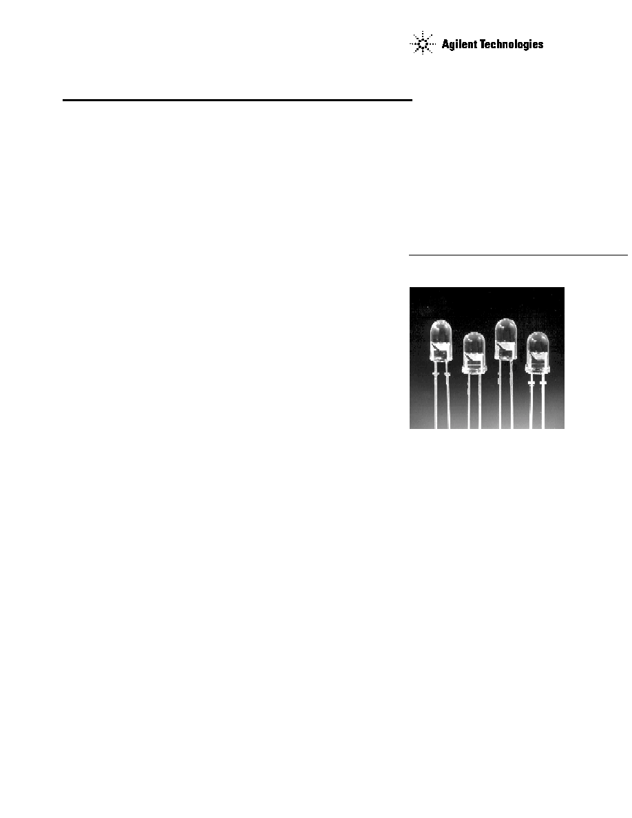
Description
These Precision Optical Perform-
ance AlInGaP LEDs provide
superior light output for
excellent readability in sunlight
and are extremely reliable.
AlInGaP LED technology
provides extremely stable light
output over long periods of time.
Precision Optical Performance
lamps utilize the aluminum
indium gallium phosphide
(AlInGaP) technology.
These LED lamps are untinted,
nondiffused, T-1
3
/
4
packages
incorporating second generation
optics producing well defined
spatial radiation patterns at
specific viewing cone angles.
SunPower Series
HLMP-ELxx
HLMP-EJxx
HLMP-EHxx
HLMP-EGxx
These lamps are made with an
advanced optical grade epoxy,
offering superior high tempera-
ture and high moisture
resistance performance in
outdoor signal and sign
applications. The high maximum
LED junction temperature limit
of +130
∞
C enables high
temperature operation in bright
sunlight conditions. The package
epoxy contains both uv-a and
uv-b inhibitors to reduce the
effects of long term exposure to
direct sunlight.
These lamps are available in two
package options to give the
designer flexibility with device
mounting.

2
Device Selection Guide
Typical
Viewing
Color and
Luminous
Angle
Dominant
Lamps Without Standoffs
Lamps With Standoffs
Intensity Iv (mcd)
[1,2]
2
1
/
2
Wavelength
on Leads
on Leads
@ 20 mA
(Deg.)
[4]
(nm), Typ.
[3]
(Outline Drawing A)
(Outline Drawing B)
Min.
Max.
HLMP-EL08-VY000
HLMP-EL10-VY000
4200
12000
HLMP-EL08-VYK00*
4200
12000
HLMP-EL08-VXK00*
4200
9300
HLMP-EL08-VX400**
4200
9300
HLMP-EL08-VX000
4200
9300
HLMP-EL08-WZ000
HLMP-EL10-WZ000
5500
16000
Amber 590
HLMP-EL08-XZ400**
7200
16000
HLMP-EL08-XZ000
7200
16000
HLMP-EL08-XZK00*
7200
16000
HLMP-EL08-XY000
7200
12000
HLMP-EL08-XYK00*
7200
12000
HLMP-EL08-X1K00*
7200
21000
HLMP-EL08-X1000
HLMP-EL10-X1000
7200
21000
6
∞
[5]
HLMP-EJ08-WZ000
HLMP-EJ10-WZ000
5500
16000
Orange 605
HLMP-EJ08-X1000
HLMP-EJ10-X1000
7200
21000
HLMP-EJ08-Y2000
HLMP-EJ10-Y2000
9300
27000
HLMP-EH08-UX000
HLMP-EH10-UX000
3200
9300
HLMP-EH08-VY000
HLMP-EH10-VY000
4200
12000
Red-Orange 615
HLMP-EH08-WZ000
HLMP-EH10-WZ000
5500
16000
HLMP-EH08-X1000
HLMP-EH10-X1000
7200
21000
HLMP-EH08-Y2000
HLMP-EH10-Y2000
9300
21000
HLMP-EG08-VW000
4200
7200
HLMP-EG08-VY000
HLMP-EG10-VY000
4200
12000
HLMP-EG08-WZ000
HLMP-EG10-WZ000
5500
16000
Red 626
HLMP-EG08-X1000
HLMP-EG10-X1000
7200
21000
HLMP-EG08-YZ000
9300
16000
HLMP-EG08-Y1000
9300
21000
HLMP-EG08-Y2000
HLMP-EG10-Y2000
9300
27000
Notes:
1. The luminous intensity is measured on the mechanical axis of the lamp package.
2. The optical axis is closely aligned with the package mechanical axis.
3. The dominant wavelength,
d
, is derived from the CIE Chromaticity Diagram and represents the color of the lamp.
4.
1/2
is the off-axis angle where the luminous intensity is one half the on-axis intensity.
5. The intensity of narrow viewing angle lamps is measured at the intensity peak.
Part numbers in bold are recommended for new designs.
*HLMP-xLxx-xxK00 are selected to amber color bins 2 and 4 only.
**HLMP-xLxx-xx400 are selected to amber color bin 4 only.

3
Typical
Viewing
Color and
Luminous
Angle
Dominant
Lamps Without Standoffs
Lamps With Standoffs
Intensity Iv (mcd)
[1,2]
2
1
/
2
Wavelength
on Leads
on Leads
@ 20 mA
(Deg.)
[4]
(nm), Typ.
[3]
(Outline Drawing A)
(Outline Drawing B)
Min.
Max.
HLMP-EL15-PS000
HLMP-EL17-PS000
880
2500
HLMP-EL15-QR000
1150
1900
HLMP-EL15-QRK00*
1150
1900
HLMP-EL15-QS000
1150
2500
HLMP-EL15-QS400**
1150
2500
HLMP-EL15-QSK00*
1150
2500
HLMP-EL15-QT000
HLMP-EL17-QT000
1150
3200
HLMP-EL15-QTK00*
1150
3200
HLMP-EL15-RU000
HLMP-EL17-RU000
1500
4200
HLMP-EL17-SV000
1900
5500
Amber 590
HLMP-EL15-TW000
HLMP-EL17-TW000
2500
7200
HLMP-EL15-TWK00*
2500
7200
HLMP-EL15-TUK00*
2500
4200
15
∞
HLMP-EL15-TV400**
2500
5500
HLMP-EL15-UX000
HLMP-EL17-UX000
3200
9300
HLMP-EL15-VY000
HLMP-EL17-VY000
4200
12000
HLMP-EL15-VYK00*
4200
12000
HLMP-EL15-VX000
4200
9300
HLMP-EL15-VXK00*
4200
9300
HLMP-EL15-VX400**
4200
9300
HLMP-EL15-VW000*
4200
7200
HLMP-EL15-VWK00*
4200
7200
HLMP-EJ15-PS000
880
2500
Orange 605
HLMP-EJ15-RU000
HLMP-EJ17-RU000
1500
4200
HLMP-EJ15-SV000
HLMP-EJ17-SV000
1900
5500
HLMP-EH15-QT000
HLMP-EH17-QT000
1150
3200
Red-Orange 615
HLMP-EH15-RU000
HLMP-EH17-RU000
1500
4200
HLMP-EH15-TW000
HLMP-EH17-TW000
2500
7200
HLMP-EH15-UX000
HLMP-EH17-UX000
3200
9300
Device Selection Guide (Continued)
Notes:
1. The luminous intensity is measured on the mechanical axis of the lamp package.
2. The optical axis is closely aligned with the package mechanical axis.
3. The dominant wavelength,
d
, is derived from the CIE Chromaticity Diagram and represents the color of the lamp.
4.
1/2
is the off-axis angle where the luminous intensity is one half the on-axis intensity.
5. The intensity of narrow viewing angle lamps is measured at the intensity peak.
Part numbers in bold are recommended for new designs.
*HLMP-xLxx-xxK00 are selected to amber color bins 2 and 4 only.
**HLMP-xLxx-xx400 are selected to amber color bin 4 only.

4
Typical
Viewing
Color and
Luminous
Angle
Dominant
Lamps Without Standoffs
Lamps With Standoffs
Intensity Iv (mcd)
[1,2]
2
1
/
2
Wavelength
on Leads
on Leads
@ 20 mA
(Deg.)
[4]
(nm), Typ.
[3]
(Outline Drawing A)
(Outline Drawing B)
Min.
Max.
HLMP-EG15-PS000
880
2500
HLMP-EG15-QT000
HLMP-EG17-QT000
1150
3200
15
∞
Red 626
HLMP-EG15-RU000
HLMP-EG17-RU000
1500
4200
HLMP-EG15-UX000
HLMP-EG17-UX000
3200
9300
HLMP-EG15-TW000
HLMP-EG17-TW000
2500
7200
HLMP-EL24-MQ000
520
1500
HLMP-EL24-NR000
HLMP-EL26-NR000
680
1900
HLMP-EL24-PS000
HLMP-EL26-PS000
880
2500
HLMP-EL24-PSK00*
880
2500
HLMP-EL24-PR400**
880
1900
HLMP-EL24-PQK00*
880
1500
HLMP-EL24-QR000
1150
1900
HLMP-EL24-QRK00*
1150
1900
HLMP-EL24-QS000
1150
2500
HLMP-EL24-QSK00*
1150
2500
HLMP-EL24-QS400**
1150
2500
23
∞
Amber 590
HLMP-EL24-QT000
HLMP-EL26-QT000
1150
3200
HLMP-EL24-QTK00*
1150
3200
HLMP-EL24-RU000
HLMP-EL26-RU000
1500
4200
HLMP-EL24-RUK00*
1500
4200
HLMP-EL26-SV000
1900
5500
HLMP-EL24-STK00*
1900
3200
HLMP-EL24-SUK00*
1900
4200
HLMP-EL24-SU400**
1900
4200
HLMP-EL24-SV000
1900
5500
HLMP-EL24-SVK00*
1900
5500
HLMP-EL24-TW000
HLMP-EL26-TW000
2500
7200
HLMP-EL24-TWK00*
2500
7200
Device Selection Guide (Continued)
Notes:
1. The luminous intensity is measured on the mechanical axis of the lamp package.
2. The optical axis is closely aligned with the package mechanical axis.
3. The dominant wavelength,
d
, is derived from the CIE Chromaticity Diagram and represents the color of the lamp.
4.
1/2
is the off-axis angle where the luminous intensity is one half the on-axis intensity.
5. The intensity of narrow viewing angle lamps is measured at the intensity peak.
Part numbers in bold are recommended for new designs.
*HLMP-xLxx-xxK00 are selected to amber color bins 2 and 4 only.
**HLMP-xLxx-xx400 are selected to amber color bin 4 only.

5
Typical
Viewing
Color and
Luminous
Angle
Dominant
Lamps Without Standoffs
Lamps With Standoffs
Intensity Iv (mcd)
[1,2]
2
1
/
2
Wavelength
on Leads
on Leads
@ 20 mA
(Deg.)
[4]
(nm), Typ.
[3]
(Outline Drawing A)
(Outline Drawing B)
Min.
Max.
Orange 605
HLMP-EJ24-QT000
HLMP-EJ26-QT000
1150
3200
HLMP-EJ24-RU000
HLMP-EJ26-RU000
1500
4200
HLMP-EH26-PS000
880
2500
Red-Orange 615
HLMP-EH24-QT000
HLMP-EH26-QT000
1150
3200
23∫
HLMP-EH24-RU000
HLMP-EH26-RU000
1500
4200
HLMP-EH24-SV000
HLMP-EH26-SV000
1900
5500
HLMP-EG24-PS000
HLMP-EG26-PS000
880
2500
Red 626
HLMP-EG24-QT000
HLMP-EG26-QT000
1150
3200
HLMP-EG24-RU000
HLMP-EG26-RU000
1500
4200
HLMP-EL30-MQ000
HLMP-EL32-MQ000
520
1500
HLMP-EL30-NR000
HLMP-EL32-NR000
680
1900
HLMP-EL30-PQ000
880
1500
HLMP-EL30-PQK00*
880
1500
HLMP-EL30-PR000
880
1900
HLMP-EL30-PR400**
880
1900
HLMP-EL30-PRK00*
880
1900
HLMP-EL30-PS000
HLMP-EL32-PS000
880
2500
30
∞
Amber 590
HLMP-EL30-PSK00*
880
2500
HLMP-EL30-QRK00*
1150
1900
HLMP-EL30-QS000
1150
2500
HLMP-EL30-QS400**
1150
2500
HLMP-EL30-QT000
HLMP-EL32-QT000
1150
3200
HLMP-EL30-QTK00*
1150
3200
HLMP-EL30-ST000
1900
3200
HLMP-EL30-SU000
1900
4200
HLMP-EL30-SU400**
1900
4200
HLMP-EL30-SUK00*
1900
4200
Device Selection Guide (Continued)
Notes:
1. The luminous intensity is measured on the mechanical axis of the lamp package.
2. The optical axis is closely aligned with the package mechanical axis.
3. The dominant wavelength,
d
, is derived from the CIE Chromaticity Diagram and represents the color of the lamp.
4.
1/2
is the off-axis angle where the luminous intensity is one half the on-axis intensity.
5. The intensity of narrow viewing angle lamps is measured at the intensity peak.
Part numbers in bold are recommended for new designs.
*HLMP-xLxx-xxK00 are selected to amber color bins 2 and 4 only.
**HLMP-xLxx-xx400 are selected to amber color bin 4 only.