
Agilent HLMP-PB00-N0000,
HLMP-PM00-N0000, HLMP-QB00-S0000,
HLMP-QM00-S0000 Subminiature
Blue and Green InGaN LED Lamps
Data Sheet
Features
∑ Subminiature flat top package
Ideal for backlighting and light
piping applications
∑ Subminiature dome package
Nondiffused dome for high
brightness
∑ Colors: 468 nm blue, 525 nm green
∑ Ideal for space limited
applications
∑ Axial leads
∑ Available with lead configura-
tions for surface mount and
through hole PC board mounting
Applications
∑ Consumer
∑ Industrial
∑ Computer peripheral
∑ Communication
Description
Flat Top Package
The HLMP-Pxxx flat top lamps use
an untinted, nondiffused, truncated
lens to provide a wide radiation
pattern that is necessary for use in
backlighting applications. The flat
top lamps are also ideal for use as
emitters in light pipe applications.
Dome Package
The HLMP-Qxxx dome lamps use an
untinted, nondiffused lens to
provide a high luminous intensity
within a narrow radiation pattern.
CAUTION: HLMP-xB00 and HLMP-xM00 LEDs are Class 2 ESD sensitive. Please observe appropriate
precautions during handling and processing. Refer to Agilent Application Note AN-1142 for addi-
tional details.
Lead Configurations
All these devices are made by
encapsulating LED chip on axial
lead frames to form molded
epoxy subminiature lamps. A
variety of package configuration
options is available. These
include special surface mount
lead configurations, gull wing,
yoke lead, or Z-bend. Right angle
lead bend at 2.54 mm (0.100
inch) and 5.08 mm (0.200 inch)
center spacing are available for
through hole mounting. For more
information refer to Standard
SMT and Through Hole Lead
Bend Options for Subminiature
Lamps data sheet.
4
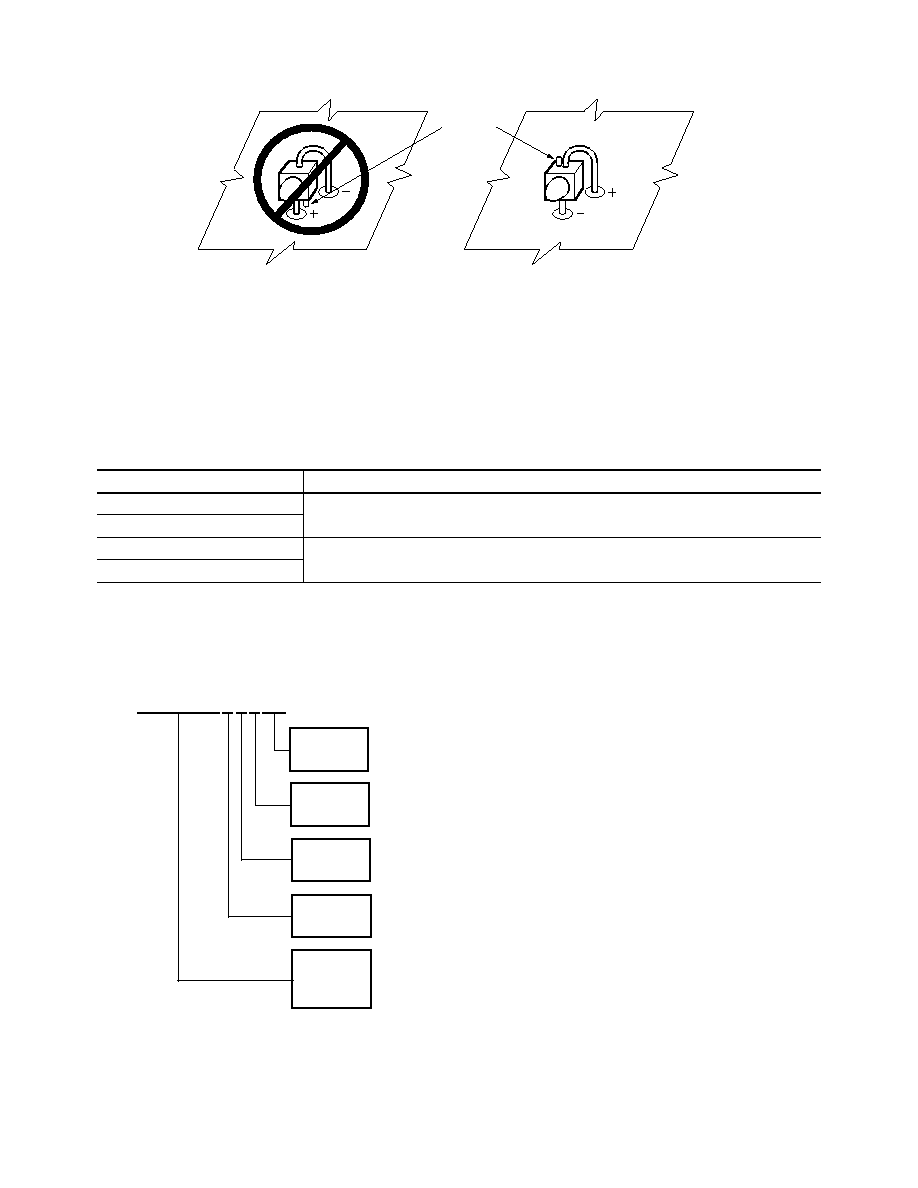
Figure 1. Proper right angle mounting to a PC board to prevent protruding cathode tab from shorting to anode connection.
NO. ANODE DOWN.
YES. CATHODE DOWN.
CATHODE
TAB
Device Selection Guide
Part Number
Color
Viewing Angle 2
1/2
Package Description
Package Outline
HLMP-PB00-N0000
Blue
85∞
Flat Top, Nondiffused, Untinted
A
HLMP-PM00-N0000
Green
HLMP-QB00-S0000
Blue
20∞
Domed, Nondiffused, Untinted
B
HLMP-QM00-S0000
Green
HLMX-XXXX-X X X X X
4 x 4 Prod.
Part
Number
Min. Iv Bin
Max. Iv Bin
Color Bin
Selection
Packaging
Option
Ordering Information

5
Optical Characteristics at T
A
= 25∞C
Luminous
Color,
Intensity
Peak
Dominant
Spectral
Viewing
Luminous
Iv (mcd) @
Wavelength
Wavelength
Halfwidth
Angle 2
1/2
Efficacy
I
F
= 20 mA
PEAK
(nm)
d
(nm)
1/2
(nm)
Degrees
v
(lm/W)
Part Number
Min.
Typ.
Typ.
Typ.
Typ.
Typ.
HLMP-PB00-N0000
25
60
470
468
26
85
70
HLMP-PM00-N0000
25
200
523
525
36
85
500
HLMP-QB00-S0000
160
290
470
468
26
20
70
HLMP-QM00-S0000
160
690
523
525
36
20
500
Absolute Maximum Ratings at T
A
= 25∞C
Parameter
Value
Peak Forward Current
90 mA
DC Forward Current
[1]
30 mA
Power Dissipation
110 mW
Reverse Voltage (I
R
= 10
µ
A)
5 V
Operating Temperature Range
≠40∞C to +85∞C
Storage Temperature Range
≠55∞C to +100∞C
LED Junction Temperature
110∞C
Lead Soldering Temperature
[1.6 mm (0.063 in.) from body]
260∞C for 5 seconds
SMT Reflow Soldering Temperatures
Convective Reflow
235∞C Peak, above 183∞C for 90 seconds
Vapor Phase Reflow
215∞C for 3 minutes
Note:
1. Derate linearly as shown in Figure 5.
Electrical Characteristics at T
A
= 25∞C
Forward Voltage
Reverse Breakdown
Capacitance C (pF),
Thermal Resistance
V
F
(Volts) @ I
F
= 20 mA
V
R
(Volts) @ I
R
= 100
µ
A
V
F
= 0, f = 1 MHz
R
J-PIN
(∞C/W)
Part Number
Typ.
Max.
Min.
Typ.
Typ.
HLMP-PB00-N0000
3.7
4.1
5
52
170
HLMP-PM00-N0000
3.7
4.1
5
52
170
HLMP-QB00-S0000
3.7
4.1
5
52
170
HLMP-QM00-S0000
3.7
4.1
5
52
170

