T-1
3
/
4
(5 mm) Precision Optical
Performance AlInGaP LED
Lamps
Technical Data
Features
∑ Well Defined Spatial
Radiation Patterns
∑ Viewing Angles: 6
∞
, 15
∞
,
23
∞
, 30
∞
∑ High Luminous Output
∑ Colors:
590 nm Amber
605 nm Orange
615 nm Reddish-Orange
626 nm Red
∑ High Operating
Temperature:
T
J LED
= +130
∞
C
∑ Superior Resistance to
Moisture
∑ Four Package Options:
With or Without Flange Base;
With or Without Lead Stand-
Offs
Benefits
∑ Viewing Angles Match
Traffic Management Sign
Requirements
∑ Colors Meet Automotive and
Pedestrian Signal
Specifications
∑ Superior Performance in
Outdoor Environments
∑ Suitable for Autoinsertion
onto PC Boards
Applications
∑ Traffic Management:
Traffic Signals
Pedestrian Signals
Work Zone Warning Lights
Variable Message Signs
∑ Commercial Outdoor
Advertising:
Signs
Marquees
∑ Automotive:
Exterior and Interior Lights
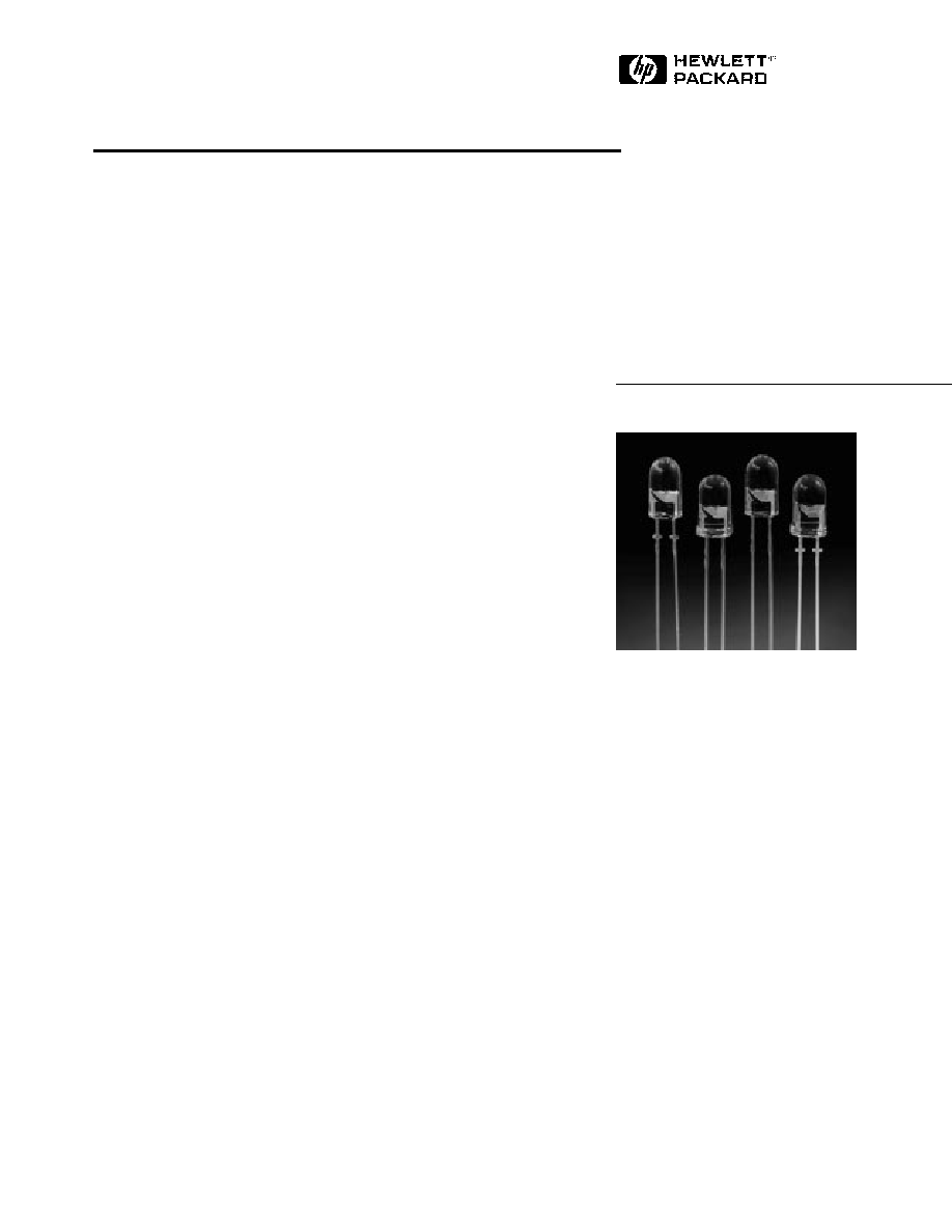
Description
These Precision Optical Perform-
ance AlInGaP LEDs provide
superior light output for excellent
readability in sunlight and are
extremely reliable. AlInGaP LED
technology provides extremely
stable light output over long
periods of time. Precision Optical
Performance lamps utilize the
aluminum indium gallium phos-
phide (AlInGaP) technology.
These LED lamps are untinted,
nondiffused, T-1
3
/
4
packages
incorporating second generation
optics producing well defined
spatial radiation patterns at
specific viewing cone angles.
SunPower Series
HLMP-DLXX
HLMP-DJXX
HLMP-DHXX
HLMP-DGXX
HLMP-GLXX
HLMP-GJXX
These lamps are made with an
advanced optical grade epoxy,
offering superior high tempera-
ture and high moisture resistance
performance in outdoor signal
and sign applications. The high
maximum LED junction tempera-
ture limit of +130
∞
C enables high
temperature operation in bright
sunlight conditions. The package
epoxy contains both uv-a and
uv-b inhibitors to reduce the
effects of long term exposure to
direct sunlight.
These lamps are available in four
package options to give the
designer flexibility with device
mounting.
HLMP-GHXX
HLMP-GGXX
HLMP-ULXX
HLMP-UJXX
HLMP-UHXX
HLMP-UGXX

Device Selection Guide
Color,
Luminous Intensity,
Part
Typical
Dominant
I
v
(mcd),
[1,2]
Number
Viewing Angle,
Wavelength,
@ 20 mA
Leads with
Flanged
Package
HLMP-
2
1
/
2
(Deg.)
[4]
d
(nm),
[3]
Typ.
Min.
Typ.
Stand-Offs
Base
Drawing
DL08
[5]
6
Amber, 590
4000
9300
No
Yes
A
GL08
[5]
6
Amber, 590
4000
9300
No
No
B
DL10
[5]
6
Amber, 590
4000
9300
Yes
Yes
C
GL10
[5]
6
Amber, 590
4000
9300
Yes
No
D
UL06
[5]
6
Amber, 590
1600
4000
No
Yes
A
UL07
[5]
6
Amber, 590
1600
4000
Yes
Yes
C
DJ08
[5]
6
Orange, 605
4200
9500
No
Yes
A
GJ08
[5]
6
Orange, 605
4200
9500
No
No
B
DJ10
[5]
6
Orange, 605
4200
9500
Yes
Yes
C
GJ10
[5]
6
Orange, 605
4200
9500
Yes
No
D
UJ06
[5]
6
Orange, 605
2000
4500
No
Yes
A
UJ07
[5]
6
Orange, 605
2000
4500
Yes
Yes
C
DH08
[5]
6
Red-Orange, 615
2900
8000
No
Yes
A
GH08
[5]
6
Red-Orange, 615
2900
8000
No
No
B
DH10
[5]
6
Red-Orange, 615
2900
8000
Yes
Yes
C
GH10
[5]
6
Red-Orange, 615
2900
8000
Yes
No
D
UH06
[5]
6
Red-Orange, 615
1400
3500
No
Yes
A
UH07
[5]
6
Red-Orange, 615
1400
3500
Yes
Yes
C
DG08
[5]
6
Red, 626
2900
6500
No
Yes
A
GG08
[5]
6
Red, 626
2900
6500
No
No
B
DG10
[5]
6
Red, 626
2900
6500
Yes
Yes
C
GG10
[5]
6
Red, 626
2900
6500
Yes
No
D
UG06
[5]
6
Red, 626
1000
3000
No
Yes
A
UG07
[5]
6
Red, 626
1000
3000
Yes
Yes
C
DL15
15
Amber, 590
1600
3100
No
Yes
A
GL15
15
Amber, 590
1600
3100
No
No
B
DL17
15
Amber, 590
1600
3100
Yes
Yes
C
GL17
15
Amber, 590
1600
3100
Yes
No
D
UL13
15
Amber, 590
700
1600
No
Yes
A
UL14
15
Amber, 590
700
1600
Yes
Yes
C
DJ15
15
Orange, 605
1400
3400
No
Yes
A
GJ15
15
Orange, 605
1400
3400
No
No
B
DJ17
15
Orange, 605
1400
3400
Yes
Yes
C
GJ17
15
Orange, 605
1400
3400
Yes
No
D
Notes:
1. The luminous intensity is measured on the mechanical axis of the lamp package.
2. The optical axis is closely aligned with the package mechanical axis.
3. The dominant wavelength,
d
, is derived from the CIE Chromaticity Diagram and represents the color of the lamp.
4.
1/2
is the off-axis angle where the luminous intensity is one half the on-axis intensity.
5. The intensity of narrow viewing angle lamps is measured at the intensity peak.

Device Selection Guide, continued
Color,
Luminous Intensity,
Part
Typical
Dominant
I
v
(mcd),
[1,2]
Number
Viewing Angle,
Wavelength,
@ 20 mA
Leads with
Flanged
Package
HLMP-
2
1
/
2
(Deg.)
[4]
d
(nm),
[3]
Typ.
Min.
Typ.
Stand-Offs
Base
Drawing
UJ13
15
Orange, 605
700
1800
No
Yes
A
UJ14
15
Orange, 605
700
1800
Yes
Yes
C
DH15
15
Red-Orange, 615
1400
2500
No
Yes
A
GH15
15
Red-Orange, 615
1400
2500
No
No
B
DH17
15
Red-Orange, 615
1400
2500
Yes
Yes
C
GH17
15
Red-Orange, 615
1400
2500
Yes
No
D
UH13
15
Red-Orange, 615
500
1400
No
Yes
A
UH14
15
Red-Orange, 615
500
1400
Yes
Yes
C
DG15
15
Red, 626
1400
2100
No
Yes
A
GG15
15
Red, 626
1400
2100
No
No
B
DG17
15
Red, 626
1400
2100
Yes
Yes
C
GG17
15
Red, 626
1400
2100
Yes
No
D
UG13
15
Red, 626
500
1000
No
Yes
A
UG14
15
Red, 626
500
1000
Yes
Yes
C
DL24
23
Amber, 590
1000
1800
No
Yes
A
GL24
23
Amber, 590
1000
1800
No
No
B
DL26
23
Amber, 590
1000
1800
Yes
Yes
C
GL26
23
Amber, 590
1000
1800
Yes
No
D
UL22
23
Amber, 590
450
1000
No
Yes
A
UL23
23
Amber, 590
450
1000
Yes
Yes
C
DJ24
23
Orange, 605
1000
2000
No
Yes
A
GJ24
23
Orange, 605
1000
2000
No
No
B
DJ26
23
Orange, 605
1000
2000
Yes
Yes
C
GJ26
23
Orange, 605
1000
2000
Yes
No
D
UJ22
23
Orange, 605
290
1200
No
Yes
A
UJ23
23
Orange, 605
290
1200
Yes
Yes
C
DH24
23
Red-Orange, 615
700
1500
No
Yes
A
GH24
23
Red-Orange, 615
700
1500
No
No
B
DH26
23
Red-Orange, 615
700
1500
Yes
Yes
C
GH26
23
Red-Orange, 615
700
1500
Yes
No
D
UH22
23
Red-Orange, 615
290
900
No
Yes
A
UH23
23
Red-Orange, 615
290
900
Yes
Yes
C
Notes:
1. The luminous intensity is measured on the mechanical axis of the lamp package.
2. The optical axis is closely aligned with the package mechanical axis.
3. The dominant wavelength,
d
, is derived from the CIE Chromaticity Diagram and represents the color of the lamp.
4.
1/2
is the off-axis angle where the luminous intensity is one half the on-axis intensity.
5. The intensity of narrow viewing angle lamps is measured at the intensity peak.

Device Selection Guide, continued
Color,
Luminous Intensity,
Part
Typical
Dominant
I
v
(mcd),
[1,2]
Number
Viewing Angle,
Wavelength,
@ 20 mA
Leads with
Flanged
Package
HLMP-
2
1
/
2
(Deg.)
[4]
d
(nm),
[3]
Typ.
Min.
Typ.
Stand-Offs
Base
Drawing
DG24
23
Red, 626
700
1300
No
Yes
A
GG24
23
Red, 626
700
1300
No
No
B
DG26
23
Red, 626
700
1300
Yes
Yes
C
GG26
23
Red, 626
700
1300
Yes
No
D
UG22
23
Red, 626
290
700
No
Yes
A
UG23
23
Red, 626
290
700
Yes
Yes
C
DL30
30
Amber, 590
700
1300
No
Yes
A
GL30
30
Amber, 590
700
1300
No
No
B
DL32
30
Amber, 590
700
1300
Yes
Yes
C
GL32
30
Amber, 590
700
1300
Yes
No
D
UL28
30
Amber, 590
300
750
No
Yes
A
UL29
30
Amber, 590
300
750
Yes
Yes
C
DJ30
30
Orange, 605
700
1500
No
Yes
A
GJ30
30
Orange, 605
700
1500
No
No
B
DJ32
30
Orange, 605
700
1500
Yes
Yes
C
GJ32
30
Orange, 605
700
1500
Yes
No
D
UJ28
30
Orange, 605
200
800
No
Yes
A
UJ29
30
Orange, 605
200
800
Yes
Yes
C
DH30
30
Red-Orange, 615
500
1100
No
Yes
A
GH30
30
Red-Orange, 615
500
1100
No
No
B
DH32
30
Red-Orange, 615
500
1100
Yes
Yes
C
GH32
30
Red-Orange, 615
500
1100
Yes
No
D
UH28
30
Red-Orange, 615
200
600
No
Yes
A
UH29
30
Red-Orange, 615
200
600
Yes
Yes
C
DG30
30
Red, 626
500
900
No
Yes
A
GG30
30
Red, 626
500
900
No
No
B
DG32
30
Red, 626
500
900
Yes
Yes
C
GG32
30
Red, 626
500
900
Yes
No
D
UG28
30
Red, 626
200
500
No
Yes
A
UG29
30
Red, 626
200
500
Yes
Yes
C
Notes:
1. The luminous intensity is measured on the mechanical axis of the lamp package.
2. The optical axis is closely aligned with the package mechanical axis.
3. The dominant wavelength,
d
, is derived from the CIE Chromaticity Diagram and represents the color of the lamp.
4.
1/2
is the off-axis angle where the luminous intensity is one half the on-axis intensity.
5. The intensity of narrow viewing angle lamps is measured at the intensity peak.

D
C
Package Dimensions
B
A
PART NO.
d
HLMP-XX10
-XX07
12.37 ± 0.25
(0.487 ± 0.010)
HLMP-XX17
-XX14
12.42 ± 0.25
(0.489 ± 0.010)
HLMP-XX26
-XX23
12.52 ± 0.25
(0.493 ± 0.010)
HLMA-XX32
-XX29
11.96 ± 0.25
(0.471 ± 0.010)
1.14 ± 0.20
(0.045 ± 0.008)
5.80 ± 0.20
(0.228 ± 0.008)
5.00 ± 0.20
(0.197 ± 0.008)
31.60
(1.244)
MIN.
0.70 (0.028)
MAX.
1.00
(0.039)
MIN.
8.71 ± 0.20
(0.343 ± 0.008)
2.54 ± 0.38
(0.100 ± 0.015)
0.50 ± 0.10
(0.020 ± 0.004)
SQ. TYP.
CATHODE
LEAD
2.35 (0.093)
MAX.
CATHODE
FLAT
1.14 ± 0.20
(0.045 ± 0.008)
5.80 ± 0.20
(0.228 ± 0.008)
5.00 ± 0.20
(0.197 ± 0.008)
31.60
(1.244)
MIN.
0.70 (0.028)
MAX.
1.00
(0.039)
MIN.
8.71 ± 0.20
(0.343 ± 0.008)
2.54 ± 0.38
(0.100 ± 0.015)
0.50 ± 0.10
(0.020 ± 0.004)
SQ. TYP.
CATHODE
LEAD
CATHODE
FLAT
d
1.50 ± 0.15
(0.059 ± 0.006)
5.00 ± 0.20
(0.197 ± 0.008)
31.60
(1.244)
MIN.
0.70 (0.028)
MAX.
1.00
(0.039)
MIN.
8.71 ± 0.20
(0.343 ± 0.008)
2.54 ± 0.38
(0.100 ± 0.015)
0.50 ± 0.10
(0.020 ± 0.004)
SQ. TYP.
CATHODE
LEAD
NOTES:
1. ALL DIMENSIONS ARE IN MILLIMETERS (INCHES).
2. LEADS ARE MILD STEEL, SOLDER DIPPED.
3. TAPERS SHOWN AT TOP OF LEADS (BOTTOM OF LAMP PACKAGE) INDICATE AN
EPOXY MENISCUS THAT MAY EXTEND ABOUT 1 mm (0.040 in.) DOWN THE LEADS.
4. RECOMMENDED PC BOARD HOLE DIAMETERS:
∑ LAMP PACKAGES A AND B WITHOUT STAND-OFFS: FLUSH MOUNTING AT BASE OF
LAMP PACKAGE = 1.143/1.067 (0.044/0.042).
∑ LAMP PACKAGES C AND D WITH STAND-OFFS: MOUNTING AT LEAD STAND-OFFS
= 0.965/0.889 (0.038/0.035).
5. FOR DOME HEIGHTS ABOVE LEAD STAND-OFF SEATING PLANE, d, LAMP PACKAGES
C AND D, SEE TABLE.
5.00 ± 0.20
(0.197 ± 0.008)
31.60
(1.244)
MIN.
0.70 (0.028)
MAX.
1.00
(0.039)
MIN.
8.71 ± 0.20
(0.343 ± 0.008)
2.54 ± 0.38
(0.100 ± 0.015)
0.50 ± 0.10
(0.020 ± 0.004)
SQ. TYP.
CATHODE
LEAD
d
1.50 ± 0.15
(0.059 ± 0.006)