 | –≠–ª–µ–∫—Ç—Ä–æ–Ω–Ω—ã–π –∫–æ–º–ø–æ–Ω–µ–Ω—Ç: HLMP-WH12 | –°–∫–∞—á–∞—Ç—å:  PDF PDF  ZIP ZIP |

SunPower Series
HLMP-WLxx
HLMP-NL06
HLMP-WHxx HLMP-NH04
HLMP-WGxx HLMP-NG07
Features
∑ T-1 (3 mm) and T-1
3
/
4
(5 mm) General Purpose
LED Lamps
∑ AlInGaP SunPower Intensity
∑ High Light Output
∑ Clear and Tinted Diffused
Lens Options
∑ Narrow and Wide Viewing
Angles
∑ Amber, Red-Orange, and Red
∑ Available on Tape and Reel
Description
This family of 3 mm and 5 mm
LED lamps is specially designed
for applications requiring higher
levels of intensity than is
achieved with a standard lamp.
The 5 mm lamp is available with
15, 30, and 65 degree viewing
angle options. The 3 mm lamp is
available with a 60 degree
viewing angle.
Applications
∑ General Purpose
∑ Consumer Goods
∑ Indicator Lights
Device Selection Guides
T-1
3/4
(5 mm) Lamp
Package
Luminous Intensity
Viewing Angle
Color
Part Number Diff.
Tint
Min. mcd, If @ 20 mA
2
1/2
(Degrees)
Amber
HLMP-WL12
450
15
Amber
HLMP-WL27
205
30
Amber
HLMP-WL02
X
X
35
65
Red Orange
HLMP-WH12
270
15
Red Orange
HLMP-WH27
155
30
Red Orange
HLMP-WH02
X
X
35
65
Red
HLMP-WG12
270
15
Red
HLMP-WG27
155
30
Red
HLMP-WG02
X
X
26
65
T-1 (3 mm) Lamp
Package
Luminous Intensity
Viewing Angle
Color
Part Number Diff.
Tint
Min. mcd, If @ 20 mA
2
1/2
(Degrees)
Amber
HLMP-NL06
96.2
60
Red Orange
HLMP-NH04
90.2
60
Red
HLMP-NG07
90.2
60
High Intensity AlInGaP
LED Lamps
Technical Data

2
2
Technical Data
Amber
Red-Orange
Red
(
d
= 590 nm)
[1]
(
d
= 615 nm)
[1]
(
d
= 626 nm)
[1]
Minimum
Minimum
Minimum
Typical
Luminous
Luminous
Luminous
Package
Viewing
Part
Intensity
Part
Intensity
Part
Intensity
Drawing/
Angle, 2
1/2
No.
I
v
(mcd)
[3,4]
,
No.
I
v
(mcd)
[3,4]
,
No.
I
v
(mcd)
[3,4]
,
Nominal
(Deg.)
[2]
HLMP-
@ 20 mA
HLMP-
@ 20 mA
HLMP-
@ 20 mA
Epoxy
Diameter
15
WL12
450
WH12
270
WG12
270
clear
A/5 mm
30
WL27
205
WH27
155
WG27
155
clear
A/5 mm
65
WL02
35
WH02
35
WG02
26
tinted
A/5 mm
diffused
[5]
60
NL06
96.2
NH04
90.2
NG07
90.2
clear
B/3 mm
Notes:
1. Dominant Wavelength,
d
, is derived from the CIE Chromaticity Diagram, and represents the color of the lamp.
2.
1/2
is the off-axis angle where the luminous intensity is one half the on-axis intensity.
3. The luminous intensity is measured on the mechanical axis of the lamp package.
4. The optical axis is closely aligned with the package mechanical axis.
5. Tinting of amber lamps is yellow, red-orange lamps are tinted a reddish orange, and red lamps are tinted red.
Package Dimensions
2.35 (0.093)
MAX.
5.00 ± 0.20
(0.197 ± 0.008)
31.60
(1.244)
MIN.
0.70 (0.028)
MAX.
1.00
(0.039)
MIN.
0.50 ± 0.10
(0.020 ± 0.004)
SQ. TYP.
CATHODE
LEAD
8.71 ± 0.20
(0.343 ± 0.008
1.14 ± 0.20
(0.045 ± 0.008)
5.80 ± 0.20
(0.228 ± 0.008)
CATHODE
FLAT
2.54 ± 0.38
(0.100 ± 0.015)
3.60
0.65 MAX.
0.44 ± 0.2
+ 0.1
≠ 0
0.4
2.54 ± 0.3
1.0 MIN.
23.0 MIN.
0.8 MAX.
(MENISCUS)
2.00
5.70 ± 0.5
3.10 ± 0.20
3.80 ± 0.30
3.35 ± 0.30
A
B

3
Electrical/Optical Characteristics at T
A
= 25
∞
C
Parameter
Symbol
Min.
Typ.
Max.
Units
Test Conditions
Forward Voltage
I
F
= 20 mA
Amber (
d
= 590 nm)
2.02
Red-Orange (
d
= 615 nm)
V
F
1.94
2.4
V
Red (
d
= 626 nm)
1.90
Reverse Voltage
V
R
5
20
V
I
R
= 100
µ
A
Peak Wavelength
Peak of Wavelength of
Amber
592
Spectral Distribution
Red-Orange
PEAK
621
nm
at I
F
= 20 mA
Red
635
Spectral Halfwidth
1/2
17
nm
Wavelength Width at
Spectral Distribution
1
/
2
Power point at
I
F
= 20 mA
Speed of Response
s
20
ns
Exponential Time
Constant, e
-t/
s
Capacitance
C
40
pF
V
F
= 0, f = 1 MHz
Thermal Resistance
R
J-PIN
240
∞
C/W
LED Junction-to-Cathode
Lead
Luminous Efficacy
[5]
Emitted Luminous
Amber
500
Power/Emitted Radiant
Red-Orange
v
235
lm/W
Power
Red
155
Note:
1. The radiant intensity, I
e
, in watts per steridian, may be found from the equation I
e
= I
v
/
v
, where I
v
is the luminous intensity in
candelas and
v
is the luminous efficacy in lumens/watt.
Absolute Maximum Ratings at T
A
= 25
∞
C
Parameter
5 mm
3 mm
DC Forward Current
50 mA
[1,3,4]
30 mA
[2,3,4]
Peak Pulsed Forward Current
[3,4]
70 mA
50 mA
Average Forward Current
30 mA
30 mA
Reverse Voltage (I
R
= 100
µ
A)
5 V
5 V
LED Junction Temperature
130
∞
C
110
∞
C
Operating Temperature
-40
∞
C to +100
∞
C
-40
∞
C to +80
∞
C
Storage Temperature
-40
∞
C to +120
∞
C
-40
∞
C to +85
∞
C
Dip/Drag Solder Temperature
260
∞
C for 5 seconds
Wave Solder Temperature
245
∞
C for 3 seconds
[1.59 mm (0.060 in.) below seating plane]
Notes:
1. Derate linearly as shown in Figure 4.
2. Derate linearly as shown in Figure 5.
3.
For long term performance with minimal light output degradation, drive currents between 10 and 30 mA are recommended.
4. Please contact your Agilent sales representative about operating currents below 10 mA.
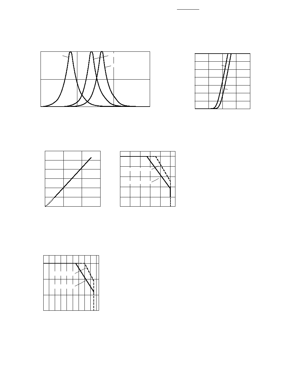
4
4
Figure 2. Forward Current vs.
Forward Voltage.
Figure 3. Relative Luminous Intensity
vs. Forward Current.
Figure 4. Maximum Forward Current
vs. Ambient Temperature for 5 mm
Lamps. Derating Based on T
JMAX
=
130
∞
C.
Figure 5. Maximum Forward Current
vs. Ambient Temperature for 3 mm
Lamps. Derating Based on T
JMAX
=
110
∞
C.
Figure 1. Relative Intensity vs. Peak Wavelength.
WAVELENGTH ≠ nm
RELATIVE INTENSITY
550
600
650
700
1.0
0.5
0
AMBER
RED-ORANGE
RED
CURRENT ≠ mA
1.0
0
VF ≠ FORWARD VOLTAGE ≠ V
2.5
40
30
1.5
2.0
60
3.0
10
20
50
AMBER
70
RED
RELATIVE LUMINOUS INTENSITY
(NORMALIZED AT 20 mA)
0
0
IF ≠ DC FORWARD CURRENT ≠ mA
40
2.5
2.0
1.0
0.5
20
60
3.0
1.5
I F
≠ FORWARD CURRENT ≠ mA
0
0
TA ≠ AMBIENT TEMPERATURE ≠ ∞C
40
80
50
40
30
20
10
20
60
100
R
JA = 585∞ C/W
R
JA = 780∞ C/W
I F
≠ FORWARD CURRENT ≠ mA
0
0
TA ≠ AMBIENT TEMPERATURE ≠ ∞C
30
80
30
20
10
20
50
90
R
JA = 500∞ C/W
R
JA = 660∞ C/W
10
40
60 70

5
Figure 7. Representative Spatial Radiation Pattern for 30
∞
Viewing Angle T-1
3/4
(5 mm) Lamps (HLMP-WX27).
Figure 8. Representative Spatial Radiation
Pattern for 65
∞
Viewing Angle Tinted/Diffused
T-1
3/4
(5 mm) Lamps (HLMP-WX02).
Figure 6. Representative Spatial Radiation Pattern for 15
∞
Viewing Angle T-1
3/4
(5 mm) Lamps (HLMP-WX12).
NORMALIZED INTENSITY ≠ %
1.0
0
ANGULAR DISPLACEMENT ≠ DEGREES
0.8
0.6
0.5
0.7
0.2
-80
-60
0.1
0.3
0.4
-40
0
20
40
60
80
100
0.9
-100
-20
RELATIVE INTENSITY ≠ %
1.0
0
ANGULAR DISPLACEMENT ≠ DEGREES
0.8
0.6
0.5
0.7
0.2
-20
-15
0.1
0.3
0.4
-10
0
5
10
15
20
25
0.9
-25
-5
RELATIVE INTENSITY ≠ %
1.0
0
ANGULAR DISPLACEMENT ≠ DEGREES
0.8
0.6
0.5
0.7
0.2
-20
-15
0.1
0.3
0.4
-10
0
5
10
15
20
25
0.9
-25
-5