 | –≠–ª–µ–∫—Ç—Ä–æ–Ω–Ω—ã–π –∫–æ–º–ø–æ–Ω–µ–Ω—Ç: HSDL-4220 | –°–∫–∞—á–∞—Ç—å:  PDF PDF  ZIP ZIP |
4-48
H
High-Performance T-1
3
/
4
(5 mm)
TS AlGaAs Infrared (875 nm)
Lamp
Technical Data
HSDL-4200 Series
HSDL-4220 30
∞
HSDL-4230 17
∞
Features
∑ Very High Power TS AlGaAs
Technology
∑ 875 nm Wavelength
∑ T-1
3
/
4
Package
∑ Low Cost
∑ Very High Intensity:
HSDL-4220 - 38 mW/sr
HSDL-4230 - 75 mW/sr
∑ Choice of Viewing Angle:
HSDL-4220 - 30
∞
HSDL-4230 - 17
∞
∑ Low Forward Voltage for
Series Operation
∑ High Speed: 40 ns Rise Times
∑ Copper Leadframe for
Improved Thermal and
Optical Characteristics
Applications
∑ Compatible with IrDA SIR
Standard
∑ IR Audio
∑ IR Telephones
∑ High Speed IR
Communications
IR LANs
IR Modems
IR Dongles
∑ Industrial IR Equipment
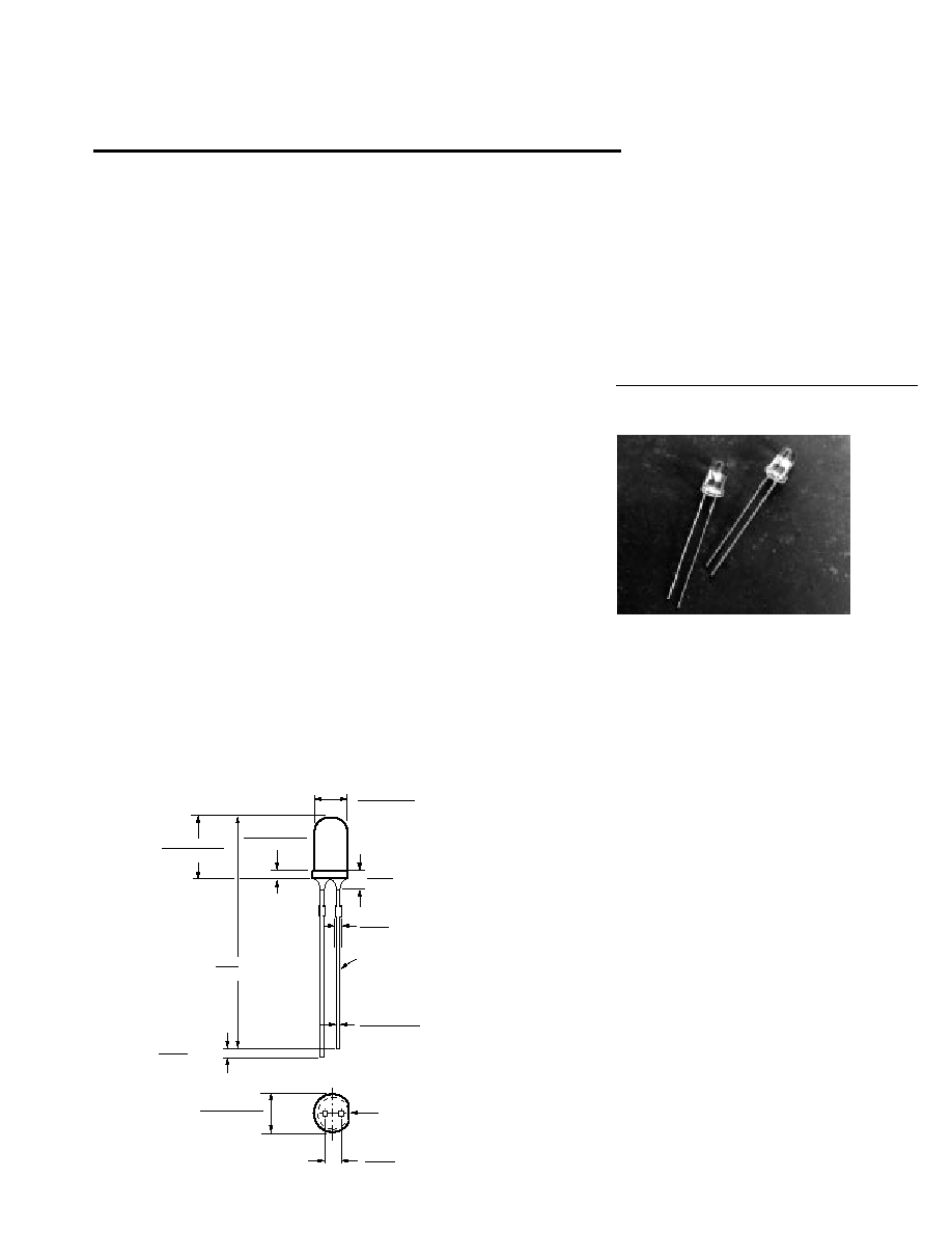
Package Dimensions
∑ IR Portable Instruments
∑ Interfaces with Crystal
Semiconductor CS8130
Infrared Transceiver
Description
The HSDL-4200 series of emitters
are the first in a sequence of
emitters that are aimed at high
power, low forward voltage, and
high speed. These emitters utilize
the Transparent Substrate, double
heterojunction, Aluminum Gal-
lium Arsenide (TS AlGaAs) LED
technology. These devices are
optimized for speed and efficiency
at emission wavelengths of 875
nm. This material produces high
radiant efficiency over a wide
range of currents up to 500 mA
peak current. The HSDL-4200
series of emitters are available in
a choice of viewing angles, the
HSDL-4230 at 17
∞
and the
HSDL-4220 at 30
∞
. Both lamps
are packaged in clear T-1
3
/
4
(5 mm) packages.
5.00
±
0.20
(0.197
±
0.008)
1.27
(0.050)
NOM.
1.14
±
0.20
(0.045
±
0.008)
8.70
±
0.20
(0.343
±
0.008)
2.35
(0.093)
MAX.
0.70
(0.028)
MAX.
0.50
±
0.10
(0.020
±
0.004)
SQUARE
CATHODE
5.80
±
0.20
(0.228
±
0.008)
CATHODE
2.54
(0.100)
NOM.
31.4
(1.23)
MIN.
5964-9642E

4-49
The wide angle emitter, HSDL-
4220, is compatible with the IrDA
SIR standard and can be used
with the HSDL-1000 integrated
SIR transceiver.
Absolute Maximum Ratings
Parameter
Symbol
Min
Max
Unit
Reference
Peak Forward Current
I
FPK
500
mA
[2], Fig. 2b
Duty Factor = 20%
Pulse Width = 100
µ
s
Average Forward Current
I
FAVG
100
mA
[2]
DC Forward Current
I
FDC
100
mA
[1], Fig. 2a
Power Dissipation
P
DISS
260
mW
Reverse Voltage (I
R
= 100
µ
A)
V
R
5
V
Transient Forward Current (10
µ
s Pulse)
I
FTR
1.0
A
[3]
Operating Temperature
T
O
0
70
∞
C
Storage Temperature
T
S
-20
85
∞
C
LED Junction Temperature
T
J
110
∞
C
Lead Soldering Temperature
260 for
∞
C
[1.6 mm (0.063 in.) from body]
5 seconds
Notes:
1. Derate linearly as shown in Figure 4.
2. Any pulsed operation cannot exceed the Absolute Max Peak Forward Current as specified in Figure 5.
3. The transient peak current is the maximum non-recurring peak current the device can withstand without damaging the LED die and
the wire bonds.
Electrical Characteristics at 25
∞
C
Parameter
Symbol
Min
Typ
Max
Unit
Condition
Reference
Forward Voltage
V
F
1.30
1.50
1.70
V
I
FDC
= 50 mA
Fig. 2a
1.40
1.67
1.85
I
FDC
= 100 mA
2.15
I
FPK
= 250 mA
Fig. 2b
Forward Voltage
V/
T
-2.1
mV/
∞
C
I
FDC
= 50 mA
Fig. 2c
Temperature Coefficient
-2.1
I
FDC
= 100 mA
Series Resistance
R
S
2.8
ohms
I
FDC
= 100 mA
Diode Capacitance
C
O
40
pF
0 V, 1 MHz
Reverse Voltage
V
R
5
20
V
I
R
= 100
µ
A
Thermal Resistance,
R
jp
110
∞
C/W
Junction to Pin
The package design of these
emitters is optimized for efficient
power dissipation. Copper
leadframes are used to obtain
better thermal performance than
the traditional steel leadframes.

4-50
Optical Characteristics at 25
∞
C
Parameter
Symbol
Min
Typ
Max
Unit
Condition
Reference
Radiant Optical Power
HSDL-4220
P
O
19
mW
I
FDC
= 50 mA
38
I
FDC
= 100 mA
HSDL-4230
P
O
16
mW
I
FDC
= 50 mA
32
I
FDC
= 100 mA
Radiant On-Axis Intensity
HSDL-4220
I
E
22
38
60
mW/sr
I
FDC
= 50 mA
Fig. 3a
76
I
FDC
= 100 mA
190
I
FPK
= 250 mA
Fig. 3b
HSDL-4230
I
E
39
75
131
mW/sr
I
FDC
= 50 mA
Fig. 3a
150
I
FDC
= 100 mA
375
I
FPK
= 250 mA
Fig. 3b
Radiant On-Axis Intensity
I
E
/
T
-0.35
%/
∞
C
I
FDC
= 50 mA
Temperature Coefficient
-0.35
I
FDC
= 100 mA
Viewing Angle
HSDL-4220
2
1/2
30
deg
I
FDC
= 50 mA
Fig. 6
HSDL-4230
2
1/2
17
deg
I
FDC
= 50 mA
Fig. 7
Peak Wavelength
PK
860
875
895
nm
I
FDC
= 50 mA
Fig. 1
Peak Wavelength
/
T
0.25
nm/
∞
C
I
FDC
= 50 mA
Temperature Coefficient
Spectral Width≠at FWHM
37
nm
I
FDC
= 50 mA
Fig. 1
Optical Rise and Fall
t
r
/t
f
40
ns
I
FDC
= 50 mA
Times, 10%-90%
Bandwidth
f
c
9
MHz
I
F
= 50 mA
Fig. 8
±
10 mA
Ordering Information
Part Number
Lead Form
Shipping Option
HSDL-4220
Straight
Bulk
HSDL-4230
Straight
Bulk

4-51
I FDC
≠ MAX. DC FORWARD CURRENT ≠ mA
0
0
TA ≠ AMBIENT TEMPERATURE ≠ ∞C
30
60
100
80
60
40
20
20
50
80
R
JA = 400 ∞C/W
40
10
70
R
JA = 300 ∞C/W
R
JA = 500 ∞C/W
NORMALIZED RADIANT INTENSITY
300
IFPK ≠ PEAK FORWARD CURRENT ≠ mA
500
0
1.5
2.0
100
400
0
0.5
200
1.0
NORMALIZED TO IFPK = 250 mA
VALID FOR PULSE
WIDTH = 1.6 µs
TO 100 µs
RELATIVE RADIANT INTENSITY
(NORMALIZED AT 50 mA)
40
100
0
IFDC ≠ DC FORWARD CURRENT ≠ mA
80
0
0.4
1.6
2.0
TA = 25 ∞C
20
60
0.8
1.2
RELATIVE RADIANT INTENSITY
850
950
0
≠ WAVELENGTH ≠ nm
900
800
0.5
1.0
1.5
TA = 25 ∞C
IFDC = 50 mA
V
F
≠ FORWARD VOLTAGE ≠ V
20
80
1.0
TA ≠ AMBIENT TEMPERATURE ≠ ∞C
60
-20
1.2
1.8
2.0
TA = 25 ∞C
0
40
1.4
1.6
IFDC = 100 mA
IFDC = 50 mA
IFDC = 1 mA
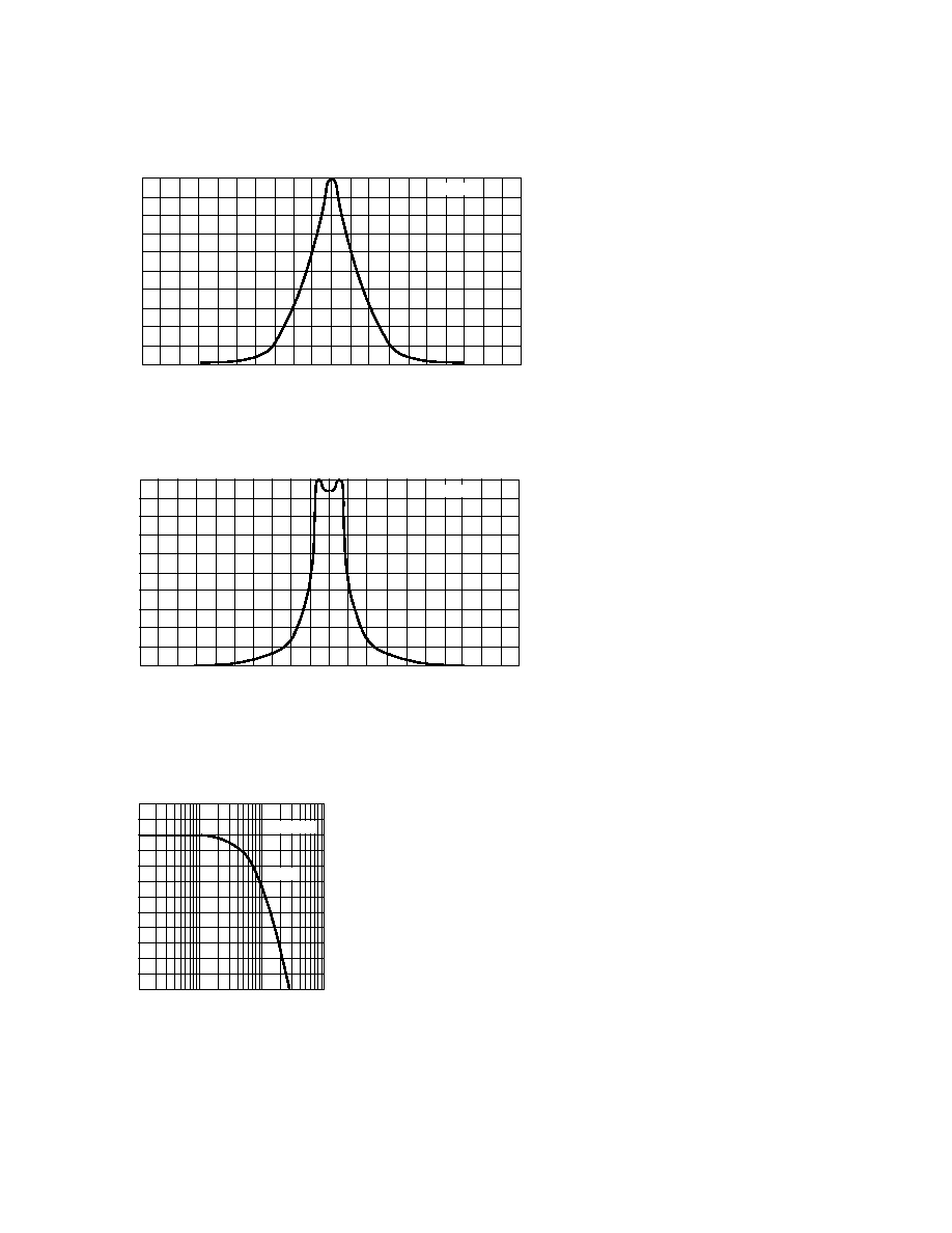
Figure 1. Relative Radiant Intensity
vs. Wavelength.
Figure 2a. DC Forward Current vs.
Forward Voltage.
Figure 2b. Peak Forward Current vs.
Forward Voltage.
Figure 2c. Forward Voltage vs
Ambient Temperature.
Figure 3a. Relative Radiant Intensity
vs. DC Forward Current.
Figure 3b. Normalized Radiant
Intensity vs. Peak Forward Current.
Figure 4. Maximum DC Forward
Current vs. Ambient Temperature.
Derated Based on T
JMAX
= 110
∞
C.
Figure 5. Maximum Peak Forward
Current vs. Duty Factor.
I FPK
≠ PEAK FORWARD CURRENT ≠ mA
0.01
100
DUTY FACTOR
1,000
1
0.1
TA = 25 ∞C
PULSE WIDTH < 100 µs
I FPK
≠ PEAK FORWARD CURRENT ≠ mA
1.0
1,000
1
VF ≠ FORWARD VOLTAGE ≠ V
1.5
2.0
2.5
3.0
0.5
0
10
100
TA = 25 ∞C
I FDC
≠ DC FORWARD CURRENT ≠ mA
1.0
VF ≠ FORWARD VOLTAGE ≠ V
2.0
0
100
1,000
0.5
1.5
1
10
TA = 25 ∞C
4-52
≠ ANGLE FROM OPTICAL CENTERLINE ≠ DEGREES (CONE HALF ANGLE)
RELATIVE RADIANT INTENSITY
1.0
0.9
0.8
0.7
0.6
0.5
0.4
0.3
0.2
0.1
0
100
∞
90
∞
80
∞
70
∞
60
∞
50
∞
40
∞
30
∞
20
∞
10
∞
0
∞
10
∞
20
∞
30
∞
40
∞
50
∞
60
∞
70
∞
80
∞
90
∞
100
∞
T = 25
∞
C
A
Figure 6. Relative Radiant Intensity vs.
Angular Displacement HSDL-4220.
≠ ANGLE FROM OPTICAL CENTERLINE ≠ DEGREES (CONE HALF ANGLE)
1.0
0.9
0.8
0.7
0.6
0.5
0.4
0.3
0.2
0.1
0
100
∞
90
∞
80
∞
70
∞
60
∞
50
∞
40
∞
30
∞
20
∞
10
∞
0
∞
10
∞
20
∞
30
∞
40
∞
50
∞
60
∞
70
∞
80
∞
90
∞
100
∞
T = 25
∞
C
A
RELATIVE RADIANT INTENSITY
Figure 7. Relative Radiant Intensity vs.
Angular Displacement HSDL-4230.
RELATIVE RADIANT INTENSITY ≠ dB
1E+6
1E+8
-10
f ≠ FREQUENCY ≠ Hz
1E+7
1E+5
-6
-2
2
TA = 25 ∞C
9 MHz
-9
-8
-7
-5
-4
-3
-1
0
1
Figure 8. Relative Radiant Intensity
vs. Frequency.
Note: At the time of this publication, Light Emitting Diodes (LEDs) that are contained in this product are regulated for eye safety in
Europe by the Commission for European Electrotechnical Standardization (CENELEC) EN60825-1. Please refer to Application Briefs
I-008, I-009, I-015 for more information.