High Performance Surface Mount
Chip LEDs
Technical Data
HSMx-S660 Series
HSMx-S670 Series
HSMx-S690 Series
Features
∑ High Brightness AlInGaP
Material
∑ Industry Standard 2.00 x
1.25 mm Package
∑ Industry Standard 1.6 x 0.8
mm (Low Profile) Package
∑ Right Angle Package
∑ Three Colors Available
∑ Diffused Optics
∑ Compatible with IR Solder
Process
∑ Available in 8 mm Tape on
7" (178 mm) Diameter Reels
Applications
∑ Keypad Backlighting
∑ LCD Backlighting
∑ Symbol Backlighting
∑ Front Panel Indicator
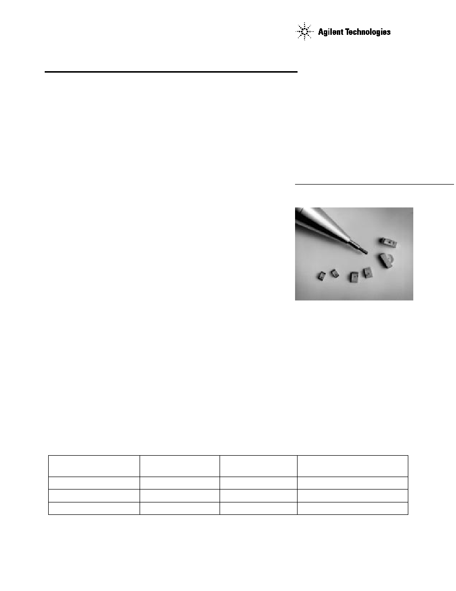
Description
These chip-type LEDs utilize
aluminum indium gallium
phosphide (AlInGaP) material
technology. The AlInGaP material
has a very high luminous
efficiency, capable of producing
high light output over a wide
range of drive currents. The 590
nm amber, 605 nm orange, and
626 nm red colors are available
in three compact, low profile
packages.
The HSMx-S670 is the industry
standard 2.0 x 1.25 mm package,
and is an excellent all around
package. The HSMx-S690 is the
industry standard 1.6 x 0.8 mm
package. Its low 0.7 mm profile
and wide viewing angle make this
LED excellent for backlighting
SunPower Series
applications. The HSMx-S660
right angle, 3.0 x 2.0 x 1.0 mm
LED is optimum for side lighting
applications where direct back-
lighting is not practical.
All packages are compatible with
IR and convective reflow solder-
ing processes.
Device Selection Guide
Footprint
Amber
Orange
Red
(mm)
[1][2]
590 nm
605 nm
626 nm
1.6 x 0.8 x 0.7
HSMA-S690
HSMD-S690
HSMC-S690
2.0 x 1.25 x 0.8
HSMA-S670
HSMD-S670
HSMC-S670
3.0 x 2.0 x 1.0
HSMA-S660
HSMD-S660
HSMC-S660
Notes:
1. Dimensions in mm.
2. Tolerance
±
0.1 mm unless otherwise noted.

2
1.6
0.8
CATHODE
MARK
(0.28)
1
1.2 1.1
0.7
0.2
2
0.35
CATHODE
POLARITY
MARK
ANODE
3
0.35
2.0
1.25
CATHODE
MARK
(0.13)
1
1.3 1.2
0.8
0.3
3
2
0.40
0.40
CATHODE
POLARITY
MARK
ANODE
+ 0.1
- 0.05
Package Dimensions
HSMx-S660 Series
HSMx-S670 Series
Notes:
1. Dimensions are in millimeters (inches).
2. Tolerance, unless otherwise specified,
±
0.1 mm (
±
0.004 inch).
HSMx-S690 Series
Absolute Maximum Ratings at T
A
= 25∫C
Parameter
HSMx-S660
HSMx-S670
HSMx-S690
Units
DC Forward Current
[1][2][3][4]
30
30
30
mA
Power Dissipation
81
81
81
mW
Reverse Voltage (I
R
= 100
µ
A)
5
5
5
V
Operating Temperature Range
- 40 to +85
-40 to +85
-40 to +85
∫C
Storage Temperature Range
- 40 to +100
-40 to +100
-40 to +100
∫C
Notes:
1. Derate linearly as shown in Figure 4.
2. Drive currents between 1 mA and 30 mA are recommended for best long term performance.
3. Operating at currents below 1 mA is not recommended. Please contact your Agilent representative for further information.
4. Maximum temperature for tape and reel packaging is 60
∞
C.
R0.8
1
3
PIN CONNECTION MARK
TO REINFORCE SOLDERING
(NON-PIN CONNECTION)
ANODE
3.0
1.0
0.3
0.3
1.0
2.0
2
(0.88)
0.25
0.25
R0.45
CATHODE
2.0
FRONT VIEW
TOP VIEW
REAR VIEW

3
Optical Characteristics at T
A
= 25∫C
Luminous
Color,
Intensity I
V
Peak
Dominant
Viewing
Luminous
(mcd) @ I
F
=
Wavelength
Wavelength
Angle 2
1/2
Efficacy
20 mA
[1]
peak
(nm)
d
[2]
(nm)
Degrees
[3]
V
Part Number
Color
Min.
Typ.
Typ.
Typ.
Typ.
(lm/W)
HSMA-S660
Amber
16.0
65.0
592
590
155
480
HSMA-S670
Amber
16.0
65.0
592
590
165
480
HSMA-S690
Amber
16.0
65.0
592
590
165
480
HSMD-S660
Orange
16.0
65.0
609
605
155
370
HSMD-S670
Orange
16.0
65.0
609
605
165
370
HSMD-S690
Orange
16.0
65.0
609
605
165
370
HSMC-S660
Red
16.0
50.0
630
626
155
197
HSMC-S670
Red
16.0
50.0
630
626
165
197
HSMC-S690
Red
16.0
50.0
630
626
165
197
Notes:
1. The luminous intensity I
V
is measured at the peak of the spatial radiation pattern which may not be aligned with the mechanical
axis of the lamp package.
2. The dominate wavelength
d is derived from the CIE Chromaticity Diagram and represents the perceived color of the device.
3.
1/2
is the off-axis angle where the luminous intensity is 1/2 the peak intensity.
Electrical Characteristics at T
A
= 25∫C
Forward
Reverse
Voltage V
F
Breakdown
Thermal
(Volts) @ I
F
V
R
(Volts) @
Capacitance C
Resistance
= 20 mA
I
R
= 100
µ
A
(pF), V
F
= 0,
R
J-PIN
Part Number
Color
Typ.
Max.
Min.
f = 1 MHz Typ.
(∫C/W)
HSMA-S660
Amber
1.9
2.4
5
45
600
HSMA-S670
Amber
1.9
2.4
5
45
300
HSMA-S690
Amber
1.9
2.4
5
45
300
HSMD-S660
Orange
1.9
2.4
5
45
600
HSMD-S670
Orange
1.9
2.4
5
45
300
HSMD-S690
Orange
1.9
2.4
5
45
300
HSMC-S660
Red
1.9
2.4
5
45
600
HSMC-S670
Red
1.9
2.4
5
45
300
HSMC-S690
Red
1.9
2.4
5
45
300

4
Note:
1. Bin categories are established for classification of products. Products may not be
available in all bin categories. Please contact your Agilent representative for
information on currently available bins.
Yellow/Amber Color Bins
[1]
Dom. Wavelength (nm)
Bin ID
Min.
Max.
A
582.0
584.5
B
584.5
587.0
C
587.0
589.5
D
589.5
592.0
E
592.0
594.5
F
594.5
597.0
Tolerance:
±
0.5 nm.
Orange Color Bins
[1]
Dom. Wavelength (nm)
Bin ID
Min.
Max.
A
597.0
600.0
B
600.0
603.0
C
603.0
606.0
D
606.0
609.0
E
609.0
612.0
F
612.0
615.0
Tolerance:
±
1 nm.

5
Note:
1. Bin categories are established for classification of products. Products may not be
available in all bin categories. Please contact your Agilent representative for
information on currently available bins.
Light Intensity (Iv) Bin Limits
[1]
Intensity (mcd)
Bin ID
Min.
Max.
A
0.11
0.18
B
0.18
0.29
C
0.29
0.45
D
0.45
0.72
E
0.72
1.10
F
1.10
1.80
G
1.80
2.80
H
2.80
4.50
J
4.50
7.20
K
7.20
11.20
L
11.20
18.00
M
18.00
28.50
N
28.50
45.00
P
45.00
71.50
Q
71.50
112.50
R
112.50
180.00
S
180.00
285.00
T
285.00
450.00
U
450.00
715.00
V
715.00
1125.00
W
1125.00
1800.00
X
1800.00
2850.00
Y
2850.00
4500.00
Tolerance
±
15%