
Alliance Semiconductor
2575 Augustine Drive . Santa Clara, CA 95054 . Tel: 408.855.4900 . Fax: 408.855.4999 . www.alsc.com
Notice: The information in this document is subject to change without notice
July 2004
Low Power µP Supervisor Circuits
ASM705 / 706 / 707 / 708
ASM813L
rev 1.2
Typical Operating Circuit
+5V Regulator
V
CC
PFI
MR
(RESET)
WDI
WDO
PFO
V
CC
(RESET)
I/O LINE
NMI
INTERRUPT
Unregulated DC
R
1
R
2
µP
ASM705
ASM706
(ASM813L)
RESET
RESET
General Description
The ASM705 / 706 / 707 / 708 and AS813L are cost effective
CMOS supervisor circuits that monitor power-supply and
battery voltage level, and µP/µC operation.
The family offers several functional options. Each device
generates a reset signal during power-up, power-down and
during brownout conditions. A reset is generated when the
supply drops below 4.65V (ASM705/707/813L) or 4.40V
(ASM706/708). For 3V power supply applications, refer to the
ASM705P/R/S/T data sheet. In addition, the ASM705/706/813L
feature a 1.6 second watchdog timer. The ASM707/708 have
both active-HIGH and active-LOW reset outputs but no
watchdog function. The ASM813L has the same pin-out and
functions as the ASM705 but has an active-HIGH reset output.
A versatile power-fail circuit has a 1.25V threshold, useful in low
battery detection and for monitoring non-5V supplies. All
devices have a manual reset (MR) input. The watchdog timer
output will trigger a reset if connected to MR.
All devices are available in 8-pin DIP, SO and MicroSO
packages.
Features
∑
Precision power supply monitor
∑4.65V threshold (ASM705/707/813L)
∑4.40V threshold (ASM706/708)
∑
Debounced manual reset input
∑
Voltage monitor
∑1.25V threshold
∑Battery monitor / Auxiliary supply monitor
∑
Watchdog timer (ASM705/706/813L)
∑
200ms reset pulse width
∑
Active HIGH reset output (ASM707/708/813L)
∑
MicroSO package
Applications
∑
Computers and embedded controllers
∑
Portable/Battery-operated systems
∑
Intelligent instruments
∑
Wireless communication systems
∑
PDAs and hendheld equipment
∑
Automative Systems
∑
Safety Systems

ASM705 / 706 / 707 / 708
2 of 15
Notice: The information in this document is subject to change without notice
Low Power µP Supervisor Circuits
ASM813L
rev 1.2
July 2004
Block Diagrams
Pin Configuration
Transition
Watchdog
Timebase
RESET
WDI
WDO
RESET
(RESET) ASM813L
MR
V
CC
PFI
PFO
GND
Detector
Timer
Generator
+
-
+
-
V
CC
0.25mA
ASM705
1.25V
+
ASM813L
4.65V (ASM705/813L)
4.40V (ASM706)
ASM706
RESET
RESET
MR
V
CC
PFI
PFO
GND
Generator
+
-
+
-
V
CC
ASM707
1.25V
+
RESET
4.65V (ASM707)
4.40V (ASM708)
0.25mA
ASM708
MR
V
CC
GND
PFI
RESET
RESET
NC
PFO
1
2
3
4
5
6
7
8
MR
V
CC
GND
PFI
(RESET)
PFO
1
2
3
4
5
6
7
8
WDI
MR
V
CC
GND
PFI
RESET
PFO
1
2
3
4
5
6
7
8
WDI
WDO
RESET
NC
MR
V
CC
GND
PFI
RESET
PFO
1
2
3
4
5
6
7
8
WDO
DIP/SO
MicroSO
ASM705
RESET
(RESET)
ASM706
(ASM813L)
ASM707
ASM708
ASM705
ASM706
(ASM813L)
ASM707
ASM708
ASM705 / 706 / 707 / 708
3 of 15
Notice: The information in this document is subject to change without notice
Low Power µP Supervisor Circuits
ASM813L
rev 1.2
July 2004
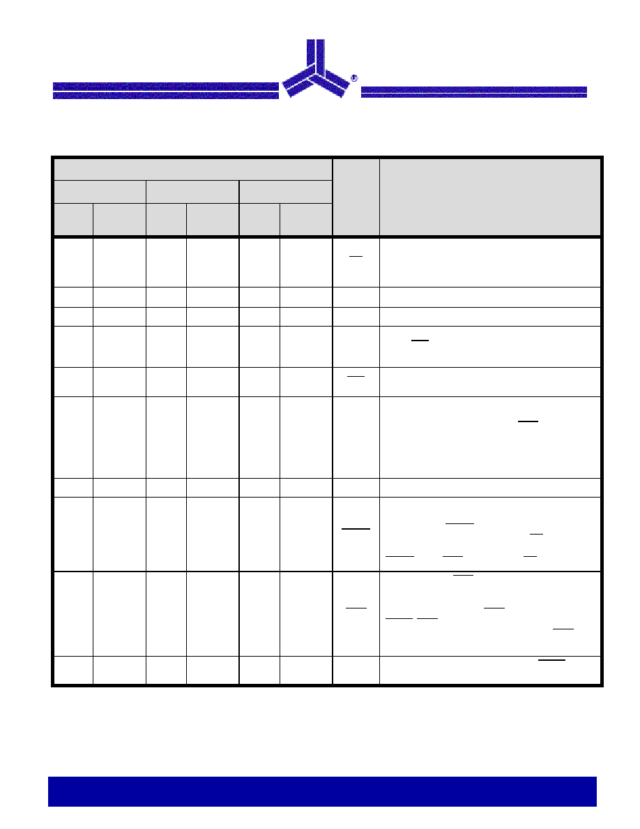
Pin Description
Pin Number
Name
Function
ASM705/706
ASM707/708
ASM813L
DIP/
SO
MicroSO
DIP/
SO
MicroSO
DIP/
SO
MicroSO
1
3
1
3
1
3
MR
Manual reset input. The active LOW input triggers a reset
pulse. A 250 µA pull-up current allows the pin to be
driven by TTL/CMOS logic or shorted to ground with a
switch.
2
4
2
4
2
4
V
CC
+5V power supply input.
3
5
3
5
3
5
GND
Ground reference for all signals.
4
6
4
6
4
6
PFI
Power-fail input voltage monitor. With PFI less than
1.25V, PFO goes LOW. Connect PFI to Ground or V
CC
when not in use.
5
7
5
7
5
7
PFO
Power-fail output. The output is active LOW and sinks
current when PFI is less than 1.25V.
6
8
-
-
6
8
WDI
Watchdog input. WDI controls the internal watchdog
timer. A HIGH or LOW signal for 1.6sec at WDI allows
the internal timer to run-out, setting WDO LOW. The
watchdog function is disabled by floating WDI or by con-
necting WDI to a high impedance three-state buffer. The
internal watchdog timer clears when: RESET is asserted;
WDI is three-stated ; or WDI sees a rising or falling edge.
-
-
6
8
-
-
NC
Not Connected
7
1
7
1
-
-
RESET
Active LOW reset output. Pulses LOW for 200ms when
triggered, and stays LOW whenever V
CC
is below the
reset threshold. RESET remains LOW for 200ms after
V
CC
rises above the reset threshold or MR goes from
LOW to HIGH. A watchdog timeout will not trigger
RESET unless WDO is connected to MR.
8
2
-
-
8
2
WDO
Watchdog output. WDO goes LOW when the 1.6 second
internal watchdog timer times-out and does not go HIGH
until the watchdog is cleared. In addition, when V
CC
falls
below the reset threshold, WDO goes LOW. Unlike
RESET, WDO does not have a minimum pulse width and
as soon as V
CC
exceeds the reset threshold, WDO goes
HIGH with no delay.
-
-
8
2
7
1
RESET
Active HIGH reset output. The inverse of RESET. The
ASM813L has only a RESET output.

4 of 15
Notice: The information in this document is subject to change without notice
Low Power µP Supervisor Circuits
ASM705 / 706 / 707 / 708
ASM813L
rev 1.2
July 2004
Detailed Description
A proper reset input enables a microprocessor /
microcontroller to start in a known state. ASM70X and
ASM813L assert reset to prevent code execution errors
during power-up, power-down and brown-out conditions.
RESET/RESET Timing
The RESET/RESET signals are designed to start a µP/µC in
a known state or return the system to a known state.
The ASM707/708 have two reset outputs, one active-HIGH
RESET and one active-LOW RESET output. The ASM813L
has only an active-HIGH output. RESET is simply the
complement of RESET.
RESET is guaranteed to be LOW with V
CC
above 1.2V.
During a power-up sequence, RESET remains low until the
supply rises above the threshold level, either 4.65V or 4.40V.
RESET goes high approximately 200ms after crossing the
threshold.
During power-down, RESET goes LOW as V
CC
falls below
the threshold level and is guaranteed to be under 0.4V with
V
CC
above 1.2V.
In a brownout situation where V
CC
falls below the threshold
level, RESET pulses low. If a brownout occurs during an
already initiated reset, the pulse will continue for a minimum
of 140ms.
Power Failure Detection With Auxiliary Comparator
All devices have an auxiliary comparator with 1.25V trip point
and uncommitted output (PFO) and noninverting input (PFI).
This comparator can be used as a supply voltage monitor
with an external resistor voltage divider. The attenuated
voltage at PFI should be set just below the 1.25 threshold. As
the supply level falls, PFI is reduced causing the PFO output
to transit LOW. Normally PFO interrupts the processor so the
system can be shut down in a controlled manner.
Manual Reset (MR)
The active-LOW manual reset input is pulled high by a 250µA
pull-up current and can be driven low by CMOS/TTL logic or
a mechanical switch to ground. An external debounce circuit
is unnecessary since the 140ms minimum reset time will
debounce mechanical pushbutton switches.
By connecting the watchdog output (WDO) and MR, a
watchdog timeout forces RESET to be generated. The
ASM813L should be used when an active-HIGH RESET is
required.
Watchdog Timer
The watchdog timer available on the ASM705/706/813L
monitors µP/µC activity. An output line on the processor is
used to toggle the WDI line. If this line is not toggled within
1.6 seconds, the internal timer puts the watchdog output,
WDO, into a LOW state. WDO will remain LOW until a toggle
is detected at WDI.
If WDI is floated or connected to a three-stated circuit, the
watchdog function is disabled, meaning, it is cleared and not
counting. The watchdog timer is also disabled if RESET is
asserted. When RESET becomes inactive and the WDI input
sees a high or low transition as short as 50ns, the watchdog
timer will begin a 1.6 second countdown. Additional
Figure 1: WDI Three-state operation
5V
V
CC
RESET
MR
WDO
5V
5V
5V
0V
0V
0V
0V
MR externally
set low
t
MD
t
MR
t
RS
V
RT
t
RS

5 of 15
Notice: The information in this document is subject to change without notice
Low Power µP Supervisor Circuits
ASM705 / 706 / 707 / 708
ASM813L
rev 1.2
July 2004
transitions at WDI will reset the watchdog timer and initiate a
new countdown sequence.
WDO will also become LOW and remain so, whenever the
supply voltage, V
CC
, falls below the device threshold level.
WDO goes HIGH as soon as V
CC
transitions above the
threshold. There is no minimum pulse width for WDO as
there is for the RESET outputs. If WDI is floated, WDO
essentially acts as a low-power output indicator.
Application Information
Ensuring That RESET is Valid Down to V
CC
= 0V
When V
CC
falls below 1.1V, the ASM705-708 RESET output
no longer pulls down; it becomes indeterminate. To avoid the
possibility that stray charges build up and force RESET to the
wrong state, a pull-down resistor should be connected to the
RESET pin, thus draining such charges to ground and
holding RESET low. The resistor value is not critical. A 100k
resistor will pull RESET to ground without loading it.
Bi-directional Reset Pin Interfacing
The ASM705/6/7/8 can interface with µP/µC bi-directional
reset pins by connecting a 4.7k
resistor in series with the
RESET output and the µP/µC bi-directional RESET pin.
Monitoring Voltages Other Than V
CC
The ASM705-708 can monitor voltages other than V
CC
using
the Power Fail circuitry. If a resistive divider is connected
from the voltage to be monitored to the Power Fail input
(PFI), the PFO will go LOW if the voltage at PFI goes below
1.25V reference. Should hysteresis be desired, connect a
resistor (equal to approximately 10 times the sum of the two
resistors in the divider) between the PFI and PFO pins. A
capacitor between PFI and GND will reduce circuit sensitivity
to input high-frequency noise. If it is desired to assert a
RESET for voltages other than V
CC
then the PFO output is to
be connected to the MR.
Supply Voltage
BUF
Buffered
RESET
V
CC
ASM70x
GND
GND
RESET
RESET
Input
µC or µP
4.7k
Bi-directional I/O Pin
Figure 3: Bi-directional Reset Pin Interfacing
V
CC
PFI
MR
PFO
V
IN
R
1
R
2
ASM70X
RESET
GND
+5V
To
µP
Figure 4: Monitoring +5V and an additional supply V
IN
WDI
WDO
RESET
RESET
Figure 2: Watchdog Timing