DC/DC CONVERTERS 66W Non-isolated DC/DC Converters
1
2 YEAR WARRANTY
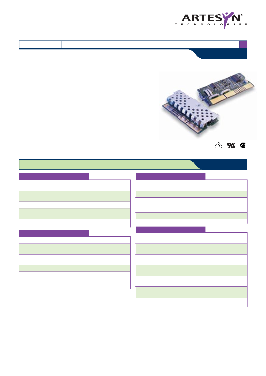
NXA66 Series
S i n g l e o u t p u t ( N o n - I s o l a t e d )
∑
Transient response from 0A to rated full load
(up to 30A/µs), recovery within 250µs
∑
Democratic current sharing, no need for master/slave
configuration
∑
Programmable output voltage
∑
Remote enable pin
∑
Power good signal
∑
True double ended differential remote sense
The NXA66 non-isolated DC/DC converter is targeted at computing applications that
require point of load power conversion. The NXA66 is designed to meet the precise
voltage and fast transient requirements of today's high performance applications such
as workstations, file servers, desktop computers, telecommunications equipment,
adapter cards, DSP and data processing. Employing synchronous rectification and
democratic current sharing, the NXA66 can be used in a stand-alone configuration, or
paralleled as a building block to achieve higher output currents or redundancy. The
current sharing specifications are met during static conditions, and transient conditions.
The advanced democratic current sharing technique employed by the NXA66 removes
the need for cumbersome master/slave combinations. The NXA66 uses gold plated
edge tab fingers for a convenient, low impedance interconnect scheme. This also
allows system designers to easily accommodate future expansion in their systems.
All specifications are typical at nominal input, full load at 25∞C unless otherwise stated
GENERAL SPECIFICATIONS
Efficiency
3V3 output
86%
2V5 output
82%
Switching frequency
Fixed
300kHz
Approvals and
EN60950
standards
Bi-national UL1950
CSA C22.2 No. 234/950
Weight
42.6g (1.5 oz)
MTBF
Bellcore 332
3,500,000 hours
ENVIRONMENTAL SPECIFICATIONS
Maximum temperature
Operating
5∞C/10 min.
shock
Temperature shock
Operating
10∞C/hour
Non-operating
20∞C/hour
Humidity
Operating
85% RH
Storage
95% RH
Altitude
Operating
10,000 feet max.
Storage
50,000 feet max.
Shock
Operational and
50G 11ms
non-operational
half sine wave
Vibration
Operational and
0.02G
2
/Hz max.
(See Note 3)
non-operational
Electrostatic discharge
Operating (See Note 4)
ESD 15kV
non-operating
ESD 25kV
OUTPUT SPECIFICATIONS
Voltage adjustability
Vout programmable
to 2V5 or 3V3
Total error band
3V3 output
4.5%
2V5 output
4.5%
Ripple and noise
(20MHz bandwidth) 150mV pk-pk max.
Transient response
50% to 75% and back
150mV
peak dev. settling time
to 1.0%, no external cap.
400µs
Short circuit protection
Continuous
Isc = 25A rms
automatic recovery
INPUT SPECIFICATIONS
Input voltage range
12Vin nominal
10.8 to 13.2VDC
Input current
No load
100mA typ.
Remote OFF
10mA max.
UVLO turn ON voltage
10.4V max.
UVLO turn OFF voltage
8.2V min.
Start-up time
Nominal line
15ms
Active high remote ON/OFF
Logic compatibility
Ref. to -input
ON
Open circuit voltage
10.8VDC min.
OFF
0.8VDC max.
SPECIFICATIONS
File Name: NXA66.PDF Rev: 31 July 2001

2.750 (69.85)
1.065 (27.05)
1.375 (34.93)
1-25 26-50
50
34 33
25
18
17
1
26
26-50 1-25
0.125 (3.18)
0.400 (10.16)
0.700 (17.78)
2.586 (65.68)
0.875 (22.23)
R0.080 (R2.03) (2 PLS)
ON CKT BOARD
HEATSINK
0.588 (14.92)
ALL DIMENSIONS IN INCHES (mm)
(See Notes 1 and 2)
Data Sheet © Artesyn TechnologiesÆ 2002
The information and specifications contained in this data sheet are believed to be correct at time of publication. However, Artesyn Technologies accepts no responsibility for consequences arising
from printing errors or inaccuracies. Specifications are subject to change without notice. No rights under any patent accompany the sale of any such product(s) or information contained herein.
For the most current data and application support visit www.artesyn.com/powergroup/products.htm
Notes
1
In this view, row B of the edge connector is visible. The leftmost pin is pin
50, and the rightmost pin is pin 26. Row A of the connector is on the
opposite side of the unit. Pin 1 is behind pin 50, pin 25 is behind pin 26.
See below for pinout.
2
Recommended mating connector is AMP 145432 or equivalent. Pin 44 is
absent and is used for electrical key. AMP keying plug PN 65025-2 may
be placed in the mating connector between pins 33 and 34, and between
pins 17 and 18. This keying plug serves as a mechanical key.
3
From 5Hz to 20Hz, maintaining 0.02G
2
/Hz from 20Hz to 500Hz, all axes.
4
Initilization level; ESD event shall cause no out-of-regulation conditions.
NXA66 Series
S i n g l e o u t p u t ( N o n - I s o l a t e d )
DC/DC CONVERTERS 66W Non-isolated DC/DC Converters
2
Please consult our website for the following items:
Longform Data Sheet
www.artesyn.com
PIN CONNECTIONS
PIN NO. ROW A
ROW B
PIN NO.
1
12V in
RTN
50
2
12V in
RTN
49
3
12V in
RTN
48
4
12V in
RTN
47
5
12V in
RTN
46
6
Reserved
RTN
45
7
VSP
8
PWRGD
Reserved
43
9
OUTEN
Ishare
42
10
Reserved
Reserved
41
11
Vo-sense
Vo-sense rtn
40
12
Vout
Return
39
13
Vout
Return
38
14
Vout
RTN
37
15
Vout
RTN
36
16
Vout
RTN
35
17
Vout
RTN
34
18
Vout
RTN
33
19
Vout
RTN
32
20
Vout
RTN
31
21
Vout
RTN
30
22
Vout
RTN
29
23
Vout
RTN
28
24
Vout
RTN
27
25
Vout
RTN
26
INPUT
NOMINAL OUTPUT
NOMINAL OUTPUT
MINIMUM
MODEL
VOLTAGE
VOLTAGE
CURRENT
EFFICIENCY
NUMBER
12VDC
3.3/2.5V
20A
86/82%
NXA66-12P3V3C
Ambient Temperature (
C)
Output Curr
ent (A)
0
2
4
6
8
10
12
14
16
18
20
10
20
30
40
50
60
70
80
90 100
400 Lfm
300 Lfm
200 Lfm
100 Lfm
Zero Air
Derating Curve
File Name: NXA66.PDF Rev: 31 July 2001