
1
Rev. 4151I≠AERO≠03/04
Features
∑
Operating Voltage: 5V
∑
Access Time: 30, 45 ns
∑
Very Low Power Consumption
≠ Active: 250 mW (Typ)
≠ Standby: 1 µW (Typ)
≠ Data Retention: 0.5 µW (Typ)
∑
Wide Temperature Range: -55
∞
C to +125
∞
C
∑
400 Mils Width Packages: FP32 and SB32
∑
TTL Compatible Inputs and Outputs
∑
Asynchronous
∑
Single 5V Supply
∑
Equal Cycle and Access Time
∑
Gated Inputs:
≠ No Pull-up/down
≠ Resistors Are Required
∑
QML Q and V with SMD 5962-89598
∑
ESCC B with Specification 9301/047
Description
The M65608E is a very low power CMOS static RAM organized as 131072 x 8 bits.
Atmel brings the solution to applications where fast computing is as mandatory as low
consumption, such as aerospace electronics, portable instruments, or embarked
systems.
Utilizing an array of six transistors (6T) memory cells, the M65608E combines an
extremely low standby supply current (Typical value = 0.2 µA) with a fast access time
at 30 ns over the full military temperature range. The high stability of the 6T cell pro-
vides excellent protection against soft errors due to noise.
The M65608E is processed according to the methods of the latest revision of the MIL
STD 883 (class B or S), ESA SCC 9000 or QML.
Rad. Tolerant
128K x 8
Very Low Power
5V CMOS SRAM
M65608E
3
M65608E
4151I≠AERO≠03/04
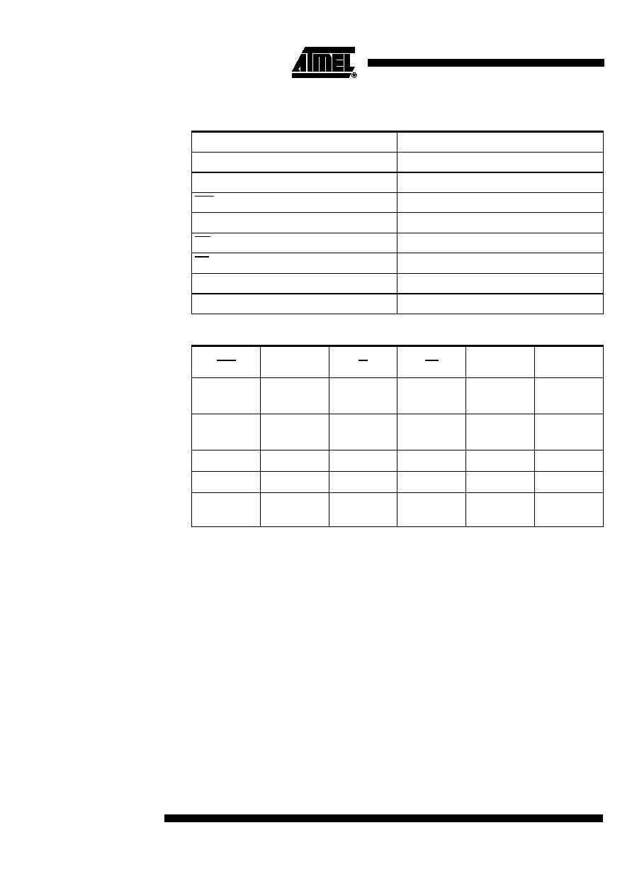
Pin Description
Table 1. Pin Names
Table 2. Truth Table
Note:
L = low, H = high, X = H or L, Z = high impedance.
Names
Description
A0 - A16
Address inputs
I/O0 - I/O7
Data Input/Output
CS1
Chip select 1
CS2
Chip select 2
WE
Write Enable
OE
Output Enable
VCC
Power
GND
Ground
CS1
CS2
W
OE
Inputs/
Outputs
Mode
H
X
X
X
Z
Deselect/
Power-down
X
L
X
X
Z
Deselect/
power-down
L
H
H
L
Data Out
Read
L
H
L
X
Data In
Write
L
H
H
H
Z
Output
Disable

4
M65608E
4151I≠AERO≠03/04
Electrical Characteristics
Absolute Maximum Ratings
Military Operating Range
Recommended DC Operating
Conditions
Capacitance
Note:
1. Guaranteed but not tested.
Supply voltage to GND potential:..........................-0.5V + 7.0V
DC input voltage: ..............................GND - 0.5V to VCC + 0.5
DC output voltage high Z state: ........GND - 0.5V to VCC + 0.5
Storage temperature: ..................................... -65
∞
C to +150
∞
C
Output current into outputs (low): .................................. 20 mA
Electro statics discharge voltage: ............................... > 2001V
(MIL STD 883D method 3015.3)
*NOTE:
Stresses greater than those listed under Absolute Max-
imum Ratings may cause permanent damage to the
device.This is a stress rating only and functional opera-
tion of the device at these or any other conditions
above those indicated in the operational sections of
this specification is not implied. Exposure to absolute
maximum rating conditions for extended periods may
affect reliability.
Operating Voltage
Operating Temperature
5V + 10%
-55
∞
C to + 125
∞
C
Parameter
Description
Minimum
Typical
Maximum
Unit
V
CC
Supply voltage
4.5
5.0
5.5
V
GND
Ground
0.0
0.0
0.0
V
V
IL
Input low voltage
GND - 0.5
0.0
0.8
V
V
IH
Input high voltage
2.2
≠
VCC + 0.5
V
Parameter
Description
Minimum
Typical
Maximum
Unit
Cin
(1)
Input low voltage
≠
≠
8
pF
Cout
(1)
Output high
voltage
≠
≠
8
pF

5
M65608E
4151I≠AERO≠03/04
DC Parameters
DC Test Conditions
Consumption
Table 3. DC Test Conditions
TA = -55
∞
C to + 125
∞
C; Vss = 0V; V
CC
= 4.5V to 5.5V
Symbol
Description
Minimum
Typical
Maximum
Unit
IIX
(1)
Input leakage
current
-1
≠
1
µA
IOZ
(1)
Output leakage
current
-1
≠
1
µA
VOL
(2)
Output low voltage
≠
≠
0.4
V
VOH
(3)
Output high
voltage
2.4
≠
≠
V
1.
GND < Vin <
V
CC
, GND < Vout <
V
CC
Output Disabled.
2.
V
CC
min. IOL = 8 mA.
3.
V
CC
min. IOH = -4 mA.
Symbol
Description
65608E-30
65608E-45
Unit
Value
ICCSB
(1)
Standby supply
current
2
2
mA
max
ICCSB1
(2)
Standby supply
current
300
300
µA
max
ICCOP
(3)
Dynamic operating
current
130
100
mA
max
1.
CS1 >
V
IH
or CS2 <
V
IL
and CS1 <
V
IL
.
2.
CS1 >
V
CC
- 0.3V or, CS2 < GND + 0.3V and CS1 < 0.2V.
3.
F = 1/TAVAV, Iout = 0 mA, W = OE =
V
IH
, Vin = GND or
V
CC
,
V
CC
max.
