 | –≠–ª–µ–∫—Ç—Ä–æ–Ω–Ω—ã–π –∫–æ–º–ø–æ–Ω–µ–Ω—Ç: Camelia4M | –°–∫–∞—á–∞—Ç—å:  PDF PDF  ZIP ZIP |

1
Main Features
∑
High Sensitivity Full Frame CCD Sensor
∑
2048 x 2048 Resolution with 14 µm Square Pixels
∑
100% Aperture Pixels
∑
12-bit Dynamic Range
∑
Very Low Noise: 66 dB SNR
∑
Binning Modes
∑
LVDS Data Format
∑
High Data Rate: 20 Mpixels/s
∑
Flexible and Easy to Operate via RS-232 Control
≠ Trigger Mode: Free Run or External Trigger Modes
≠ Binning 2 x 2 and 4 x 4
≠ Exposure Time
≠ Gain: x1 to x8
≠ 3-Shot Color Operation
∑
Single Power Supply: DC 24V
∑
High Reliability ≠ CE Compliant
∑
F (Nikon) Mount Adapter (Lens Not Supplied)
Product Description
This camera is designed to meet high performance and quality requirements while
providing ease of use.
∑
ATMEL manages the whole process, from the sensor to the camera. The result is
a camera that works in 12-bit, with dedicated electronics that provides an
excellent signal to noise ratio.
∑
The sensitivity of the camera is fairly high even in the near infrared thanks to the
100% aperture pixel.
∑
The programmable settings let the user work at different integration times and
gains. The external trigger allows synchronization of the camera on an external
event, while the 3-shot color mode allows very high resolution for color image
acquisition.
Applications
Performance and reliability of this camera make it well suited for the most demanding
applications such as film and document scanning, semiconductor and PCB inspec-
tion, DNA analysis, metrology, X-ray imaging.
CAMELIA
4M
Full Frame Black
and White and
3-Shot Color
Digital Camera
Rev. 5301B≠IMAGE≠04/03

2
CAMELIA 4M Digital Camera
5301B≠IMAGE≠04/03
Camelia Package
Contents
Depending on the selected configuration, a Camelia package may include:
∑
Camelia camera
∑
FGT frame grabber board
∑
Power supply Cable and RS-232 cable
∑
Data and Sync cable
∑
COMMCAM software
∑
FGT software
∑
Documentation
System
Requirements
∑
24V (0.6A) power supply
∑
Computer:
≠
Minimal configuration:
PENTIUM II 350 MHz
RAM: 128 Mb, 256 Mb for 3-shot color mode
Cache memory: 256 Kb
1 free PCI slot
≠
Operating System:
Windows
Æ
NT 4.0
Windows
Æ
95b, 98
∑
NIKON lens
∑
Lighting control (shutter/chopper or pulsed lighting)
Getting Started
1. Connect the camera to one of the computer serial ports (COM1 or COM2) by
using the RS-232 cable.
2. Power on the camera.
3. Install the COMMCAM software in your computer (see the "COMMCAM User
Guide").
4. Install the FGT frame grabber board and the FGT software on your computer
(see the "FGT Frame Grabber User Guide").
5. Run the system.
3
CAMELIA 4M Digital Camera
5301B≠IMAGE≠04/03
Imaging System
Description
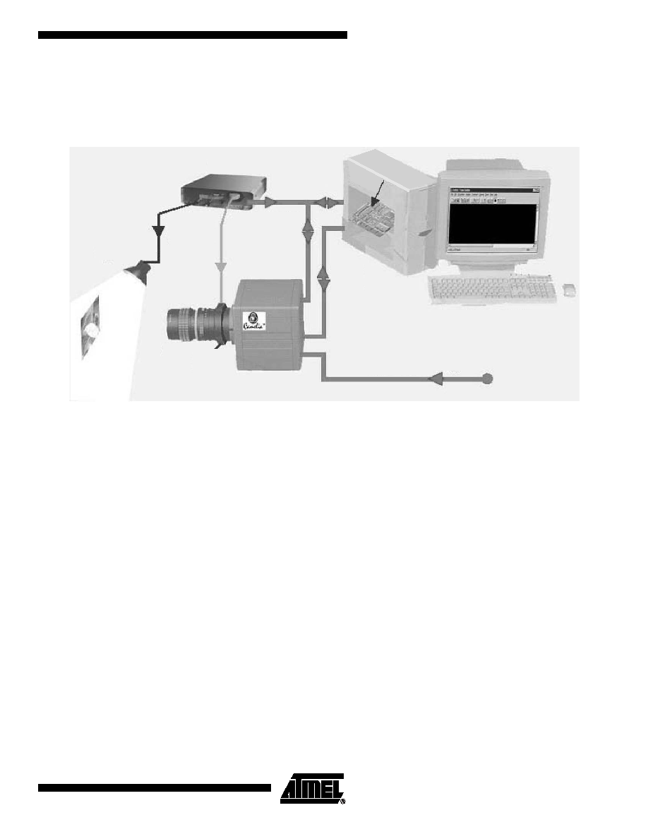
Figure 1. Imaging System
The Camelia 4M is powered by a 24V power supply and is configured through the serial
port of the computer. The camera sends digital video to the FGT frame grabber.
As Camelia's CCD is a full frame sensor, either pulsed lighting or a chopper/shutter
must be used in front of the camera during integration time in order to have incident
lighting on the CCD. The user must design an electro-optical interface to drive the cam-
era, shutter/chopper or lighting by using the SHUTTER signal delivered by the camera.
If required, the system can send an external trigger or external ITC (integration time
control) signal to the camera.
Light Source
Light &
Shutter
Trigger
Cables
Lens
Shutter
& BG38
Camera
Power Supply Cable
24V
RS-232
Cable
Data &
Sync
Cable
Control Box
Computer
FGT
Frame Grabber

4
CAMELIA 4M Digital Camera
5301B≠IMAGE≠04/03
Camelia 4M Camera
CCD Description
∑
Image format: 28.7 mm (V) x 28.7 mm (H)
∑
2048 mm (V) x 2048 mm (H) active pixels
∑
Readout register along the small side of the image area (vertical image)
∑
Pixel geometry:
≠
14 µm (V) x 14 µm (H)
≠
100% aperture ratio
∑
Antiblooming by clocking
Timing
2 x 2 and 4 x 4 pixel binning can be used to enable previewing modes.
Data rate (pixel clock): 20 MHz
Three timing modes are available:
∑
Continuous
∑
External triggered
∑
Integration time controlled (ITC)
Continuous Timing Mode
The camera delivers frames continuously:
∑
Frame N+1 integration starts as soon as frame N readout is completed.
∑
Integration time is set by RS-232.
Figure 2. Continuous Timing Diagram
Table 1. Frame Readout Time
Mode
Frame Readout Times
No binning
235 ms
2 x 2 pixel binning
125 ms
4 x 4 pixel binning
70 ms
3
2048 pixels
Int. time set by RS-232
FEN
LEN
Video lines
2
1
2048
2047
2046
SHUTTER
Frame
integration
Shutter
delay
Frame
readout
2 ms

5
CAMELIA 4M Digital Camera
5301B≠IMAGE≠04/03
External Trigger Timing Mode
The external TRIG signal allows the user to control the start of frame integration:
∑
The rising edge of TRIG activates the start of frame integration. This rising edge is
synchronized by the camera with a precision of 112 µs.
∑
Integration time is set by RS-232.
∑
Note that the TRIG signal period must be greater than the sum of the integration
time and the frame readout time.
Figure 3. External Trigger Timing Diagram
Integration Time Control (ITC)
Timing Mode
The external ITC signal allows the user to fully control frame integration:
∑
The falling edge of ITC activates the start of frame integration. This falling edge is
synchronized by the camera with a precision of 112 µs.
∑
The rising edge of ITC activates the stop of frame integration. This rising edge is
synchronized by the camera with a precision of 112 µs.
∑
Note that the ITC signal period must be greater than the sum of the integration time
(defined by ITC low) and the frame readout time.
Figure 4. "Integration Time Control" Timing Diagram
Antiblooming by
Clocking
Antiblooming can be activated or inhibited (see "RS-232 Interface" on page 8):
∑
Antiblooming OFF: antiblooming inhibited. Recommended if antiblooming is not
required for the application.
∑
Antiblooming ON: antiblooming activated.
3
2048 pixels
Video lines
2
1
2048
2047
2046
Int. time set by RS-232
Frame
integration
Shutter
delay
Frame
readout
LEN
FEN
TRIG
Waiting
SHUTTER
3
2048 pixels
Video lines
2
1
2048
2047
2046
Frame
integration
Shutter
delay
Frame
readout
Waiting
LEN
SHUTTER
FEN
ITC