Rev. 4666B≠CORD≠08/04
Features
∑
Speech Circuit with Anti-clipping
∑
Tone-ringer Interface with DC/DC Converter
∑
Speaker Amplifier with Anti-distortion
∑
Power-supply Management (Regulated, Unregulated) and a Special Supply for Electret
Microphone
∑
Voice Switch
∑
Interface for Answering Machine and Cordless Phone
Applications
∑
Feature Phone
∑
Answering Machine
∑
Fax Machine
∑
Speaker Phone
∑
Cordless Phone
Benefits
∑
No Piezoelectric Transducer for Tone Ringing Necessary
∑
Complete System Integration of Analog Signal Processing on One Chip
∑
Very Few External Components
Description
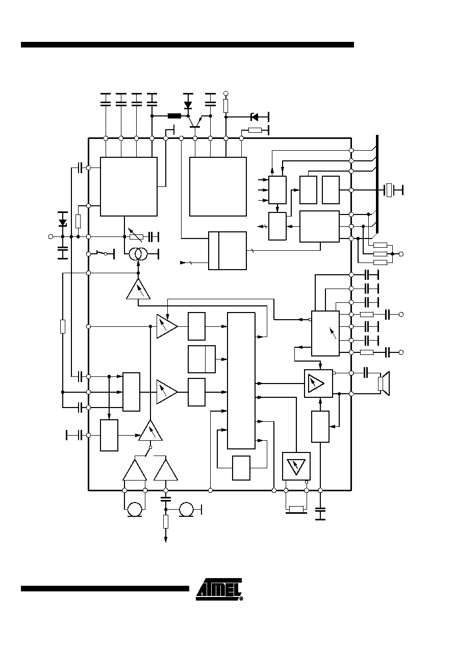
The programmable telephone audio processor U4091BM-N is a linear integrated cir-
cuit for use in feature phones, answering machines and fax machines. It contains the
speech circuit, tone-ringer interface with DC/DC converter, sidetone equivalent and
ear-protection rectifiers. The circuit is line-powered and contains all components nec-
essary for signal amplification and adaptation to the line. The U4091BM-N can also be
supplied via an external power supply. An integrated voice switch with loudspeaker
amplifier enables hands-free or loudhearing operation. With an anti-feedback function,
acoustic feedback during loudhearing can be reduced significantly. The generated
supply voltage is suitable for a wide range of peripheral circuits.
Programmable
Telephone
Audio
Processor
U4091BM-N

5
U4091BM-N
4666B≠CORD≠08/04
Pin Description
Pin
Symbol
Function
1
RECIN
Receive amplifier input
(1)
2
TXACL
Time constant adjustment for transmit anti-clipping
3
MIC3
Microphone input for hands-free operation
4
MIC2
Input of symmetrical microphone amplifier with high common-mode rejection ratio
5
MIC1
Input of symmetrical microphone amplifier with high common-mode rejection ratio
6
RECO2
Output of the receive amplifier
7
RECO1
Output of the receive amplifier, also used for sidetone network
8
IND
The internal equivalent inductance of the circuit is proportional to the value of the capacitor at this pin. A
resistor connected to ground may be used to adjust the DC mask.
9
VL
Positive supply-voltage input to the device in speech mode
10
SENSE
Input for sensing the available line current
11
GND
Ground, reference point for DC and AC signals
12
VB
Unstabilized supply voltage for speech network
13
SAO2
Negative output of speaker amplifier (push-pull only)
14
SAO1
Positive output of speaker amplifier (single ended and push-pull operation)
15
VMPS
Unregulated supply voltage for the microcontroller (via series regulator to VMP)
16
VMP
Regulated output voltage for supplying the microcontroller (typically 3.3 V/6 mA in speech mode)
17
VMIC
Reference node for microphone amplifier, supply for electret microphones
18
TSACL
Time constant for speaker amplifier anti-clipping
19
VRING
Input for ringer supply
20
IMPA
Input for adjusting the ringer input impedance
21
COSC
70-kHz oscillator for ringing power converter
22
SWOUT
Output for driving the external switch resistor
23
INT
Interrupt line for serial bus
24
SCL
Clock input for serial bus
25
SDA
Data line for serial bus
26
OSCIN
Input for 3.58-MHz oscillator
27
RESET
Reset output for the microcontroller
28
OSCOUT
Clock output for the microcontroller
29
ES
Input for external supply indication
30
ADIN
Input of A/D converter
31
BNMR
Output of background-noise monitor receive
32
BNMT
Output of background-noise monitor transmit
33
CT
Time constant for mode switching of voice switch
34
TLDR
Time constant of receive-level detector
35
INLDR
Input of receive-level detector
36
INLDT
Input of transmit-level detector
37
TLDT
Time constant of transmit-level detector
38
IMPSW
Switch for additional line impedance
Note:
1. The protection device at Pin RECIN is disconnected.