1
Features
∑
28-bit Prescaler
∑
Programmable Time-out Period
∑
Fully Synchronous
∑
Protected Turn-off Sequence
∑
Up to 100% Fault Coverage with Scan Test
Description
The AVR
Æ
embedded RISC microcontroller core is a low power, CMOS 8-bit micropro-
cessor based on AVR RISC architecture. With this core, Atmel supplies a bus-
compatible Watchdog Timer.
The watchdog timer generates a time-out signal if it has not been reset after a certain
number of clock cycles. This can be used to exit from endless loops.
The watchdog timer is a fully synchronous peripheral.
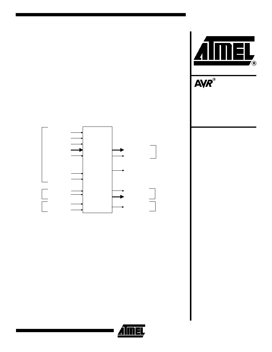
Figure 1. Watchdog Timer Pin Configuration
wdt_irqack
cp2
dbus_in[7:0]
iore
iowe
ireset
dbus_out[7:0]
out_en
Watchdog
Timer
test_se
test_si
test_so
AVR Control
AVR Control
wdri
Scan Test
Scan Test
runmod
cs
Watchdog
Watchdog
wdtmout
wdcnt[28:0]
wdt_irq
Embedded RISC
Microcontroller
Core Peripheral
Watchdog Timer
Rev. 1344B≠06/01

2
Watchdog Timer
1344B≠06/01
Table 1. Pin Description
Pin Name
Function
I/O
Comments
AVR Control
cp2
CPU Clock
Input
Any register in the watchdog timer will update its content only on the
rising edge of cp2.
ireset
Synchronous Reset
Input
When high, ireset will reset internal registers by reading the value on
dbus_in, which is forced to zero by the AVR core.
runmod
Run Control
Input
When low, runmod stops all the internal functions (count) of the
watchdog timer. Only the interface register continues to function
normally.
dbus_out[7:0]
Data Bus Output
Output
Valid only when accompanied by a strobe on out_en, otherwise held
at zero.
dbus_in[7:0]
Data Bus Input
Input
Data bus input.
out_en
Output Enable
Output
When high, out_en indicates that the watchdog timer requires the
control of the data bus.
cs
Chip Select
Input
When high, iore and iowe are used to access the internal Watchdog
Timer I/O. When low, the watchdog timer cannot be accessed in read
or write mode. cs is generated by decoding the AVR address bus,
adr[5:0].
iore
I/O Read Strobe
Input
Used to read the content of the I/O location addressed adr[5:0].
iowe
I/O Write Strobe
Input
Used to update the content of the I/O location addressed adr[5:0].
Watchdog Timer
wdt_irq
Watchdog IRQ Flag
Output
This IRQ flag is set if WDIE is high and a Watchdog time-out occurs.
It is reset by ireset, wdt_irqack, or by a one written in WDIRQ bit.
wdt_irqack
Watchdog IRQ
Acknowledge
Input
When high, this signal indicates that the watchdog interrupt has been
acknowledged.
wdri
Watchdog Reset Input
Input
Watchdog reset instruction input. When high, wdri resets the
watchdog.
wdtmout
Watchdog Time-out
Output
Depending on WDTCR[3:0], wdtmout will indicate the time-out of the
watchdog.
wdcnt[28:0]
Watchdog Counter
Output
State of internal watchdog timer.
Test Scan
test_se
Scan Enable Output
Input
Test scan enable (active high).
test_si
Scan Chain 1 Input
Input
Scan chain input.
test_so
Scan Chain 1 Output
Output
Scan chain output.

3
Watchdog Timer
1344B≠06/01
Figure 2. Watchdog Timer
Functional
Description
The watchdog timer is clocked by the system clock cp2. By controlling the watchdog timer
prescaler, the watchdog time-out interval can be adjusted from 16K to 262,144K x T
CP2
. The
WDR - Watchdog Reset - instruction resets the watchdog timer. Fifteen different multiples of
the clock cycle period can be selected to determine the time-out period. If the time-out period
expires without another watchdog reset, the wdtmout pin is held high during half the watchdog
time-out period, or until wdri is asserted. This assertion must reset the AVR core.
To prevent unintentional disabling of the watchdog, a special turn-off sequence must be fol-
lowed while the watchdog is enabled. Refer to the description of the Watchdog Timer Control
Register for details.
Watchdog
Timer Chip
Select (CS)
The watchdog timer has the ability to be remapped inside the AVR I/O address range. To
access the internal I/O location of the watchdog timer, the following condition must be true:
cs = 1
Under this condition, iore and iowe are used to access internal I/O to read or write. The cs
input is the result of decoding the AVR adr bus with the following code:
cs = (adr[5:0] ==BaseAdr)
BaseAdr is the Base Address of the watchdog timer. It locates the Watchdog Timer Control
Register, WDTCR.
A small amount of glue logic must be inserted by the designer to implement the above code.
wdtmout
cp2
wdri
f
CP2
/16K
f
CP2
/32K
f
CP2
/64K
f
CP2
/128K
f
CP2
/256K
f
CP2
/512K
f
CP2
/1024K
f
CP2
/32768K
f
CP2
/4096K
f
CP2
/2048K
f
CP2
/16384K
f
CP2
/8192K
f
CP2
/65536K
f
CP2
/131072K
f
CP2
/262144K
WDP0
WDP1
WDP2
WDP3
WDE
From Watchdog Timer Control
Register WDTCR
Watchdog
Prescaler

4
Watchdog Timer
1344B≠06/01
Watchdog Timer Control Register
Name:
WDTCR
Access:
Read/Write
∑ WDP0, WDP1, WDP2, WDP3: Watchdog Timer Prescaler 0, 1, 2 and 3:
The WDP0, WDP1, WDP2 and WDP3 bits determine the Watchdog Timer prescaling when the Watchdog Timer is
enabled. The different prescaling values and their corresponding timeout periods are shown in Table 2.
The WDP0, WDP1, WDP2 and WDP3 bits must be set before enabling the Watchdog Timer.
∑ WDE: Watchdog Enable
When the WDE is set (one) the Watchdog Timer is enabled, and if the WDE is cleared (zero) the watchdog timer function is
disabled. WDE can only be cleared if the WDTOE bit is set (one). To disable an enabled watchdog timer, the following pro-
cedure must be followed:
1.
In the same operation, write a logical one to WDTOE and WDE. A logical one must be written to WDE even though
it is already set to one before the disable operation starts.
2.
Within the next four clock cycles, write a logical zero to WDE. This disables the watchdog.
∑ WDTOE: Watchdog Turn-off Enable:
This bit must be set (one) when the WDE bit is cleared. Otherwise, the Watchdog Timer will not be disabled. Once set,
hardware will clear this bit to zero after four clock cycles. Refer to the description of the WDE bit for the watchdog disable
procedure.
∑ WDIRQ: Watchdog Interrupt flag:
This IRQ flag is set if WDIE is high and a Watchdog time-out occurs. It is reset by ireset, wdt_irqack, or by a one written in
WDIRQ bit.
∑ WDIE: Watchdog Interrupt Enable:
This bit forces the Watchdog to generate an interrupt instead of Watchdog time-out reset.
7
6
5
4
3
2
1
0
WDIE
WDIRQ
WDTOE-
WDE
WDP3
WDP2
WDP1
WDP0

5
Watchdog Timer
1344B≠06/01
Scan Test
Configuration
The AVR Watchdog Timer peripheral has been designed with a full scan methodology which
results in a 100% maximum fault coverage.
The coverage is maximum if all non-scan inputs can be controlled and all non-scan outputs
can be observed. In order to achieve this, the ATPG vectors must be generated on the entire
circuit (top level) which includes the AVR watchdog timer.
The scan test pins can then be connected for serial or parallel scan.
Table 2. Watchdog Timer Prescale Select
WDP3
WDP2
WDP1
WDP0
Timeout Period
0
0
0
0
16K x T
CP2
0
0
0
1
32K x T
CP2
0
0
1
0
64K x T
CP2
0
0
1
1
128K x T
CP2
0
1
0
0
256K x T
CP2
0
1
0
1
512K x T
CP2
0
1
1
0
1024K x T
CP2
0
1
1
1
2048K x T
CP2
1
0
0
0
4096K x T
CP2
1
0
0
1
8192K x T
CP2
1
0
1
0
16384K x T
CP2
1
0
1
1
32768K x T
CP2
1
1
0
0
65536K x T
CP2
1
1
0
1
131072K x T
CP2
1
1
1
0
262144K x T
CP2
1
1
1
1
Reserved