
232PE3095 Manual
Cover Page
B&B Electronics -- PO Box 1040 -- Ottawa, IL 61350
PH (815) 433-5100 -- FAX (815) 434-7094
Port Expander
Model 232PE
Document No. 232PE3095
This product
Designed and Manufactured
In Ottawa, Illinois
USA
of domestic and imported parts by
B&B Electronics Mfg. Co. Inc.
707 Dayton Road -- P.O. Box 1040 -- Ottawa, IL 61350
PH (815) 433-5100 -- FAX (815) 434-7094
Internet:
http://www.bb-elec.com
sales@bb-elec.com
techsupt@bb.elec.com
©
1993 B&B Electronics -- June 1993

232PE3095 Manual
Table of Contents
i
B&B Electronics -- PO Box 1040 -- Ottawa, IL 61350
PH (815) 433-5100 -- FAX (815) 434-7094
TABLE OF CONTENTS
Chapter 1: HARDWARE....................................................1
Introduction .........................................................................1
Checklist .............................................................................2
Port Expansion Bus.............................................................2
Setting The Address............................................................2
Connecting To The Bus.......................................................4
Port Configuration ...............................................................5
RS-232 Configuration.......................................................5
RS-422/485 Option ..........................................................6
RS-422 Mode................................................................7
RS-485 Mode................................................................8
Specifications....................................................................10
Appendix A: Cable Charts ........................................... A-1
Chart 1. IBM PC DB25 Connector to Master Port ........... A-2
Chart 2. IBM PC DB9 Connector to Master Port ............. A-2
Chart 3. Modem DB25 Connector to Master Port............ A-3
Chart 4. DCE Device w/DB25 Connector to Ports A - D
(DTE) .................................................................... A-3
Chart 5. IBM PC DB25 Connector to Ports A - D (DTE).. A-4
Chart 6. IBM PC DB9 Connector to Ports A - D (DTE).... A-4
Chart 7. IBM PC DB25 Connector to Ports A - D (DTE).. A-5
Chart 8. IBM PC DB9 Connector to Ports A - D(DTE)..... A-5
Chart 9. RS-422/485 4-Wire Device to Port (A - D)
Configured as an RS-422 /485 Port....................... A-6
Chart 10. RS-422/485 2-Wire Device to Port (A - D)
Configured as an RS-422 /485 Port....................... A-6

ii
Table of Contents
232PE3095 Manual
B&B Electronics -- PO Box 1040 -- Ottawa, IL 61350
PH (815) 433-5100 -- FAX (815) 434-7094
232PE3095 Manual
1
B&B Electronics -- PO Box 1040 -- Ottawa, IL 61350
PH (815) 433-5100 -- FAX (815) 434-7094
Chapter 1: HARDWARE
Introduction
The Port Expander (232PE) adds four asynchronous serial data
ports to the Expandable Smart Switch (232XSS). Up to fifteen Port
Expanders can be connected to a single 232XSS via the Port
Expansion Bus. Refer to Figure 1. This expands the eight ports on
the 232XSS to a maximum of sixty-eight ports. RS-232 ports are
standard on the 232PE, RS-422/485 ports are optional. RS-232
ports are configured as DTE ports and support signals TD, RD,
RTS, CTS, DTR, and DSR or CD. Ports configured as RS-422/485
support only signals TD and RD.
There are five red indicator LED's on the front of the 232XSS.
Four LED's represent ports "A" through "D" and indicate the
selected port. The fifth LED is the "Power On" indicator. Refer to
Figure 7. There are five connectors located on the back of the
232PE, a twenty pin expansion bus connector, four DB-25P male
connectors for ports "A" through "D", and an eleven inch bus
expansion ribbon cable. Refer to Figure 8.
In order to select a port on a Port Expander, each expander is
assigned its own unique address. A four position DIP switch in the
Port Expander is used to set this address. An address field is part
of the port selection control string that is received by the master
port of the Expandable Smart Switch. Refer to the Expandable
Smart Switch manual for more details regarding port selection.
There is no delay through the Port Expander and the data is not
buffered.
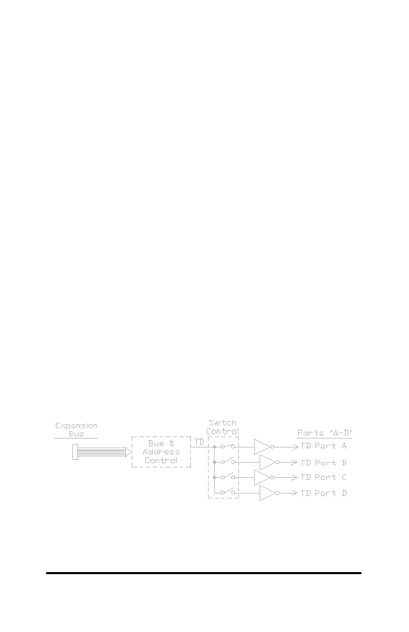
Figure 1. Simplified Functional Diagram
This diagram illustrates only the transmit data (TD) signal.
