 | –≠–ª–µ–∫—Ç—Ä–æ–Ω–Ω—ã–π –∫–æ–º–ø–æ–Ω–µ–Ω—Ç: ADC7802BP | –°–∫–∞—á–∞—Ç—å:  PDF PDF  ZIP ZIP |
ADC7802
Autocalibrating, 4-Channel, 12-Bit
ANALOG-TO-DIGITAL CONVERTER
FEATURES
q
TOTAL UNADJUSTED ERROR
1/2LSB
OVER FULL TEMPERATURE RANGE
q
FOUR-CHANNEL INPUT MULTIPLEXER
q
LOW POWER: 10mW plus Power Down
Mode
q
SINGLE SUPPLY: +5V
q
FAST CONVERSION TIME: 8.5
µ
s Including
Acquisition
q
AUTOCAL: No Offset or Gain Adjust
Required
q
UNIPOLAR INPUTS: 0V to 5V
q
MICROPROCESSOR-COMPATIBLE
INTERFACE
q
INTERNAL SAMPLE/HOLD
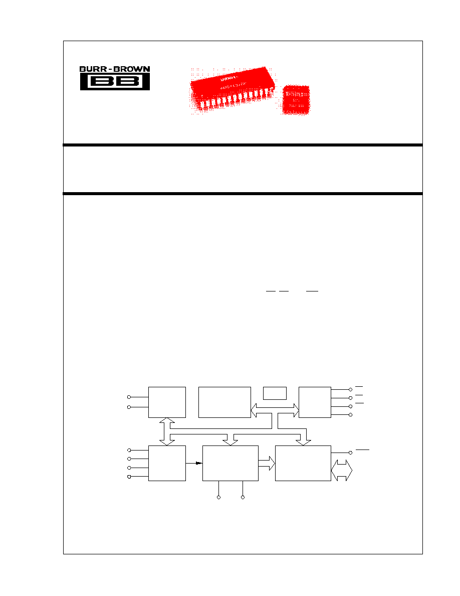
DESCRIPTION
The ADC7802 is a monolithic CMOS 12-bit A/D
converter with internal sample/hold and four-channel
multiplexer. An autocalibration cycle, occurring auto-
matically at power on, guarantees a total unadjusted
error within
±
1/2LSB over the specified temperature
range, eliminating the need for offset or gain adjust-
ment. The 5V single-supply requirements and stan-
dard CS, RD, and WR control signals make the part
very easy to use in microprocessor applications. Con-
version results are available in two bytes through an 8-
bit three-state output bus.
The ADC7802 is available in a 28-pin plastic DIP and
28-lead PLCC, fully specified for operation over the
industrial ≠40
∞
C to +85
∞
C temperature range.
Clock
Control
Logic
Calibration
Microcontroller
and Memory
Address
Latch and
Decoder
Analog
Multiplexer
Capacitor Array
Sampling ADC
Three-State
Input/Output
BUSY
8-Bit
Data Bus
V
REF
AIN0
AIN1
AIN2
AIN3
CS
RD
WR
SFR
V
REF
+
≠
A0
A1
Æ
International Airport Industrial Park ∑ Mailing Address: PO Box 11400 ∑ Tucson, AZ 85734 ∑ Street Address: 6730 S. Tucson Blvd. ∑ Tucson, AZ 85706
Tel: (520) 746-1111 ∑ Twx: 910-952-1111 ∑ Cable: BBRCORP ∑ Telex: 066-6491 ∑ FAX: (520) 889-1510 ∑ Immediate Product Info: (800) 548-6132
© 1990 Burr-Brown Corporation
PDS-1050B
Printed in U.S.A. June, 1993
2
Æ
ADC7802
SPECIFICATIONS
ELECTRICAL
At V
A
= V
D
= V
REF
+
= 5V
±
5%; V
A
V
D
V
REF
+; V
REF
≠ = AGND = DGND = 0V; CLK = 2MHz external with 50% duty cycle, T
A
= ≠40
∞
C to +85
∞
C, after calibration
cycle at any temperature, unless otherwise specified.
PARAMETER
CONDITIONS
MIN
TYP
MAX
UNITS
RESOLUTION
12
Bits
ANALOG INPUT
Voltage Input Range
V
REF
+ = 5V, V
REF
≠ = 0V
0
5
V
Input Capacitance
50
pF
On State Bias Current
100
nA
Off State Bias Current
T
A
= 25
∞
C
10
nA
T
A
= ≠40
∞
C to +85
∞
C
100
nA
On Resistance Multiplexer
2
k
Off Resistance Multiplexer
10
M
Channel Separation
500Hz
92
dB
REFERENCE INPUT
For Specified Performance: V
REF
+
V
REF
+
V
A
5
V
V
REF
≠
0
V
For Derated Performance:
(1)
V
REF
+
4.5
V
A
V
V
REF
≠
0
1
V
Input Reference Current
V
REF
+ = 5V, V
REF
≠ = 0V
10
100
µ
A
THROUGHPUT TIMING
Conversion Time With External Clock (Including
CLK = 2MHz, 50% Duty Cycle
8.5
µ
s
Multiplexer Settling Time and Acquisition Time)
CLK = 1MHz, 50% Duty Cycle
17
µ
s
CLK = 500kHz, 50% Duty Cycle
34
µ
s
With Internal Clock Using
T
A
= +25
∞
C
10
µ
s
Recommended Clock Components
T
A
= ≠40
∞
C to +85
∞
C
10
µ
s
Analog Signal Bandwidth
(2)
500
Hz
Slew Rate
(2)
8
mV/
µ
s
Multiplexer Settling Time to 0.01%
460
ns
Multiplexer Access Time
20
ns
ACCURACY
Total Adjusted Error,
(3)
All Channels
±
1/2
LSB
Differential Nonlinearity
±
1/2
LSB
No Missing Codes
Guaranteed
Gain Error
All Channels
±
1/4
LSB
Gain Error Drift
Between Calibration Cycles
±
0.2
ppm/
∞
C
Offset Error
All Channels
±
1/4
LSB
Offset Error Drift
Between Calibration Cycles
±
0.2
ppm/
∞
C
Channel-to-Channel Mismatch
±
1/4
LSB
Power Supply Sensitivity
V
A
= V
D
= 4.75V to 5.25V
±
1/8
LSB
DIGITAL INPUTS
All Pins Other Than CLK: V
IL
0.8
V
V
IH
2.4
V
Input Current
T
A
= +25
∞
C, V
IN
= 0 to V
D
1
µ
A
T
A
= ≠40
∞
C to +85
∞
C, V
IN
= 0 to V
D
10
µ
A
CLK Input: V
IL
0.8
V
V
IH
3.5
V
I
IL
10
µ
A
I
IH
1.5
mA
I
IH
Power Down Mode (D3 in SFR HIGH)
100
nA
DIGITAL OUTPUTS
V
OL
I
SINK
= 1.6mA
0.4
V
V
OH
I
SOURCE
= 200
µ
A
4
V
Leakage Current
High-Z State, V
OUT
= 0V to V
D
±
1
µ
A
Output Capacitance
High-Z State
4
15
pF
POWER SUPPLIES
Supply Voltage for Specified Performance: V
A
4.75
5
5.25
V
V
D
V
A
V
D
4.75
5
5.25
V
Supply Current: I
A
1
2.5
mA
I
D
Logic Input Pins HIGH or LOW
1
2
mA
Power Dissipation
WR = RD = CS = BUSY = HIGH
10
mW
Power Down Mode
See Table III, Page 9
50
µ
W
TEMPERATURE RANGE
Specification
≠40
+85
∞
C
Storage
≠65
+150
∞
C
NOTES: (1) For (V
REF
+) ≠ (V
REF
≠) as low as 4.5V, the total error will typically not exceed
±
1LSB. (2) Faster signals can be accurately converted by using an external
sample/hold in front of the ADC7802. (3) After calibration cycle, without external adjustment. Includes gain (full scale) error, offset error, integral nonlinearity,
differential nonlinearity, and drift.
ADC7802BP, ADC7802BN

3
Æ
ADC7802
The information provided herein is believed to be reliable; however, BURR-BROWN assumes no responsibility for inaccuracies or omissions. BURR-BROWN assumes
no responsibility for the use of this information, and all use of such information shall be entirely at the user's own risk. Prices and specifications are subject to change
without notice. No patent rights or licenses to any of the circuits described herein are implied or granted to any third party. BURR-BROWN does not authorize or warrant
any BURR-BROWN product for use in life support devices and/or systems.
ABSOLUTE MAXIMUM RATINGS
V
A
to Analog Ground ........................................................................... 6.5V
V
D
to Digital Ground ............................................................................ 6.5V
Pin V
A
to Pin V
D
................................................................................
±
0.3V
Analog Ground to Digital Ground .........................................................
±
1V
Control Inputs to Digital Ground ................................... ≠0.3V to V
D
+ 0.3V
Analog Input Voltage to Analog Ground ...................... ≠0.3V to V
D
+ 0.3V
Maximum Junction Temperature ..................................................... 150
∞
C
Internal Power Dissipation ............................................................. 875mW
Lead Temperature (soldering, 10s) ................................................ +300
∞
C
Thermal Resistance,
JA
: Plastic DIP ............................................. 75
∞
C/W
PLCC ..................................................... 75
∞
C/W
PACKAGE INFORMATION
PACKAGE DRAWING
MODEL
PACKAGE
NUMBER
(1)
ADC7802BN
28-Pin PLCC
251
ADC7802BP
28-Pin Plastic DIP
215
NOTE: (1) For detailed drawing and dimension table, please see end of data
sheet, or Appendix D of Burr-Brown IC Data Book.
ORDERING INFORMATION
MAXIMUM
SPECIFICATION
TOTAL
TEMPERATURE
MODEL
ERROR, LSB
RANGE,
∞
C
PACKAGE
ADC7802BN
±
1/2
≠40 to +85
PLCC
ADC7802BP
±
1/2
≠40 to +85
Plastic DIP

4
Æ
ADC7802
PIN CONFIGURATIONS
Top View
DIP
Top View
LCC
PIN ASSIGNMENTS
PIN #
NAME
DESCRIPTION
1
SFR
Special Function Register. When connected to a microprocessor address pin, allows access to special functions through D0 to
D7. See the sections discussing the Special Function Register. If not used, connect to DGND. This pin has an internal pull-down.
2 to 5
AIN0 to AIN3
Analog inputs. Channel 0 to channel 3.
6
V
REF
+
Positive voltage reference input. Normally +5V. Must be
V
A
.
7
V
REF
≠
Negative voltage reference input. Normally 0V.
8
DGND
Digital ground. DGND = 0V.
9
V
D
Logic supply voltage. V
D
= +5V. Must be
V
A
and applied after V
A
.
10 to 17
D0 to D7
Data Bus Input/Output Pins. Normally used to read output data. See section on SFR (Special Function Register) for other
uses.
When SFR is LOW, these function as follows:
10
D7
Data Bit 7 if HBE is LOW; if HBE is HIGH, acts as converter status pin and is HIGH during conversion or calibration, goes
LOW after the conversion is completed. (Acts as an inverted BUSY.)
11
D6
Data Bit 6 if HBE is LOW; LOW if HBE is HIGH.
12
D5
Data Bit 5 if HBE is LOW; LOW if HBE is HIGH.
13
D4
Data Bit 4 if HBE is LOW; LOW if HBE is HIGH.
14
D3
Data Bit 3 if HBE is LOW; Data Bit 11 (MSB) if HBE is HIGH.
15
D2
Data Bit 2 if HBE is LOW; Data Bit 10 if HBE is HIGH.
16
D1
Data Bit 1 if HBE is LOW; Data Bit 9 if HBE is HIGH.
17
D0
Data Bit 0 (LSB) if HBE is LOW; Data Bit 8 if HBE is HIGH.
18
RD
Read Input. Active LOW; used to read the data outputs in combination with CS and HBE.
19
CS
Chip Select Input. Active LOW.
20
WR
Write Input. Active LOW; used to start a new conversion and to select an analog channel via address inputs A0 and A1 in
combination with CS. The minimum WR pulse LOW width is 100ns.
21
HBE
High Byte Enable. Used to select high or low data output byte in combination with CS and RD, or to select SFR.
22
BUSY
BUSY is LOW during conversion or calibration. BUSY goes HIGH after the conversion is completed.
23
CLK
Clock Input. For internal/external clock operation. For external clock operation, connect pin 23 to a 74 HC-compatible clock
source. For internal clock operation, connect pin 23 per the clock operation description.
24 to 25
A0 to A1
Address Inputs. Used to select one of four analog input channels in combination with CS and WR. The address inputs are
latched on the rising edge of WR or CS.
A1
A0
Selected Channel
LOW
LOW
AIN0
LOW
HIGH
AIN1
HIGH
LOW
AIN2
HIGH
HIGH
AIN3
26
CAL
Calibration Input. A calibration cycle is initiated when CAL is LOW. The minimum pulse width of CAL is 100ns. If not used,
connect to V
D
. In this case calibration is only initiated at power on, or with SFR. This pin has an internal pull-up.
27
AGND
Analog Ground. AGND = 0V.
28
V
A
Analog Supply. V
A
= +5V. Must be
V
D
and V
REF
+.
4
3
2
1
28
27
26
AIN2
AIN1
AIN0
SFR
V
AGND
CAL
A
A1
CLK
A0
BUSY
HBE
WR
CS
AIN3
DGND
V
D
D7
D6
12
13 14
15
16
17 18
D5
D4
D3
D2
D1
D0
RD
5
6
7
8
9
10
11
25
24
23
22
21
20
19
+
REF
V
≠
REF
V
SFR
AIN0
AIN1
AIN2
AIN3
V +
V ≠
DGND
V
D7
D6
D5
D4
D3
V
AGND
CAL
A1
A0
CLK
BUSY
HBE
WR
CS
RD
D0
D1
D2
1
2
3
4
5
6
7
8
9
10
11
12
13
14
28
27
26
25
24
23
22
21
20
19
18
17
16
15
REF
REF
D
A
5
Æ
ADC7802
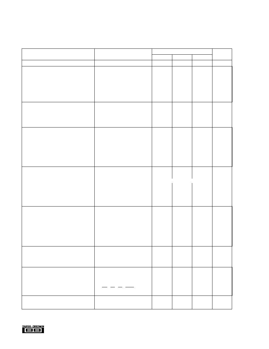
TYPICAL PERFORMANCE CURVES
At V
A
= V
D
= V
REF
+ = 5V, V
REF
≠ = AGND = 0V, T
A
= +25
∞
C, unless otherwise specified.
CHANNEL SEPARATION vs FREQUENCY
100
80
60
40
20
0
Channel Separation (dB)
1
10
100
1000
Frequency of 5Vp-p Signal on Channel AIN2 (kHz)
Channel AIN3
Channel AIN1
Channel AIN0
Conversions Yielding Expected Code (%)
Analog Input Voltage ≠ Expected Code Center (LSBs)
CODE TRANSITION NOISE
0
100
75
50
25
0
0.25
0.5
0.75
1
75
50
25
0
SIGNAL/(NOISE + DISTORTION)
vs INPUT FREQUENCY
0.1
0.2
0.4
1
10
4
2
Input Frequency (kHz)
0.6
6
Signal/(Noise + Distortion) (dB)
POWER SUPPLY REJECTION vs FREQUENCY
Full-Scale Error vs
Change in Supply Voltage (mV/V)
10
6
4
2
1
0.6
0.4
0.2
0.1
Frequency (kHz)
0.1
1
10
100
1000
V
A
V
D
INTERNAL CLOCK FREQUENCY
vs TEMPERATURE
Clock Frequency (MHz)
Ambient Temperature (∞C)
1.15
1.1
1.05
1
0.95
0.9
≠50
≠25
0
25
50
75
100
R
CLOCK
= 70k
INTERNAL CLOCK FREQUENCY
vs R
CLOCK
10
1
0.1
Clock Frequency (MHz)
10
100
1k
R
CLOCK
(k
)

6
Æ
ADC7802
THEORY
OF OPERATION
ADC7802 uses the advantages of advanced CMOS technol-
ogy (logic density, stable capacitors, precision analog
switches, and low power consumption) to provide a precise
12-bit analog-to-digital converter with on-chip sampling and
four-channel analog-input multiplexer.
The input stage consists of an analog multiplexer with an
address latch to select from four input channels.
The converter stage consists of an advanced successive
approximation architecture using charge redistribution on a
capacitor network to digitize the input signal. A temperature-
stabilized differential auto-zeroing circuit is used to mini-
mize offset errors in the comparator. This allows offset errors
to be corrected during the acquisition phase of each conver-
sion cycle.
Linearity errors in the binary weighted main capacitor net-
work are corrected using a capacitor trim network and
correction factors stored in on-chip memory. The correction
terms are calculated by a microcontroller during a calibration
cycle, initiated either by power-up or by applying an external
calibration signal at any time. During conversion, the correct
trim capacitors are switched into the main capacitor array as
needed to correct the conversion accuracy. This is faster than
a complex digital error correction system, which could slow
down the throughput rate. With all of the capacitors in both
the main array and the trim array on the same chip, excellent
stability is achieved, both over temperature and over time.
For flexibility, timing circuits include both an internal clock
generator and an input for an external clock to synchronize
with external systems. Standard control signals and three-
state input/output registers simplify interfacing ADC7802 to
most micro-controllers, microprocessors or digital storage
systems.
Finally, this performance is matched with the low-power
advantages of CMOS structures to allow a typical power
consumption of 10mW.
OPERATION
BASIC OPERATION
Figure 1 shows the simple circuit required to operate
ADC7802 in the Transparent Mode, converting a single
input channel. A convert command on pin 20 (WR) starts a
conversion. Pin 22 (BUSY) will output a LOW during the
conversion process (including sample acquisition and con-
version), and rises only after the conversion is completed.
The two bytes of output data can then be read using pin 18
(RD) and pin 21 (HBE).
STARTING A CONVERSION
A conversion is initiated on the rising edge of the WR input,
with valid signals on A0, A1 and CS. The selected input
channel is sampled for five clock cycles, during which the
comparator offset is also auto-zeroed to below 1/4LSB of
error. The successive approximation conversion takes place
during clock cycles 6 through 17.
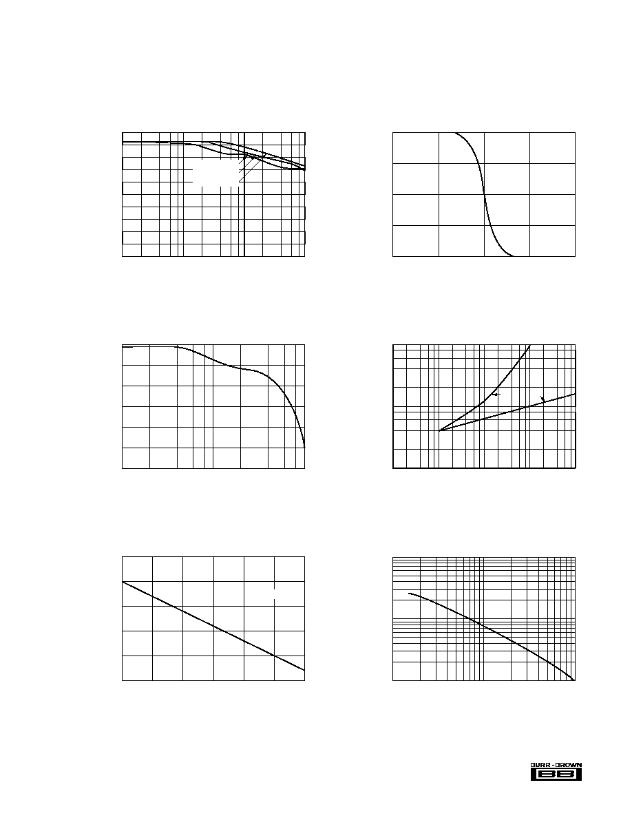
FIGURE 1. Basic Operation.
Figures 2 and 3 show the full conversion sequence and the
timing to initiate a conversion.
CALIBRATION
A calibration cycle is initiated automatically upon power-up
(or after a power failure). Calibration can also be initiated by
the user at any time by the rising edge of a minimum 100ns-
wide LOW pulse on the CAL pin (pin 26), or by setting D1
HIGH in the Special Function Register (see SFR section). A
calibration command will initiate a calibration cycle, regard-
less of whether a conversion is in process. During a calibra-
tion cycle, convert commands are ignored.
Calibration takes 168 clock cycles, and a normal conversion
(17 clock cycles) is added automatically. For maximum
accuracy, the supplies and reference need to be stable during
the calibration procedure. To ensure that supply voltages and
reference voltages have settled and are stable, an internal
timer provides a waiting period of 42,425 clock cycles
between power-up/power-failure and the start of the calibra-
tion cycle.
READING DATA
Data from the ADC7802 is read in two 8-bit bytes, with the
Low byte containing the 8 LSBs of data, and the High byte
containing the 4 MSBs of data. The outputs are coded in
straight binary (with 0V = 000 hex, 5V = FFF hex), and the
data is presented in a right-justified format (with the LSB as
the most right bit in the 16-bit word). Two read operations are
required to transfer the High byte and Low byte, and the
bytes are presented according to the input level on the High
Byte Enable pin (HBE).
SFR
AIN0
AIN1
AIN2
AIN3
V +
V ≠
DGND
V
D7
D6
D5
D4
D3
V
AGND
CAL
A1
A0
CLK
BUSY
HBE
WR
CS
RD
D0
D1
D2
1
2
3
4
5
6
7
8
9
10
11
12
13
14
28
27
26
25
24
23
22
21
20
19
18
17
16
15
REF
REF
D
A
+
10nF
10µF
+5V
0-5V
Input
BUSY
LOW
LOW
LOW
Data Bit 7
Data Bit 6
Data Bit 5
Data Bit 4
Data Bit 3
Data Bit 11
(MSB)
HBE Input
HIGH
HBE Input
LOW
Data Bit 1
Data Bit 2
Data Bit 8
Data Bit 9
Data Bit 10
HBE Input
LOW
HBE Input
HIGH
Data Bit 0
(LSB)
Read Command
BUSY
Convert Command
High Byte
Enable Command
+
10µF
10nF
+5V
100k
NC
NC
7
Æ
ADC7802
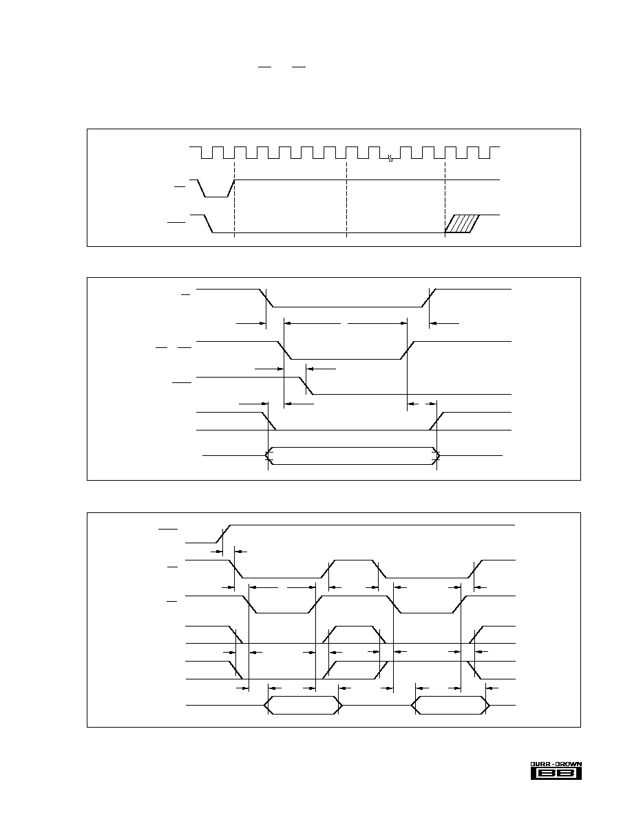
ADC7802 provides two modes for reading the conversion
results. At power-up, the converter is set in the Transparent
Mode.
The bytes can be read in either order, depending on the status
of the HBE input. If HBE changes while CS and RD are
LOW, the output data will change to correspond to the HBE
input. Figure 4 shows the timing for reading first the Low
byte and then the High byte.
FIGURE 2. Converter Timing.
Multiplexer Settling,
Offset Auto Zeroing
and Sample Acquisition
Successive
Approximation
Conversion
BUSY
WR
CLK
1
2
3
4
5
6
7
16
17
18
FIGURE 4. Read Cycle Timing.
BUSY
CS
RD
SFR
HBE
D0 - D7
Hi-Z State
Hi-Z
Low Byte Data
High Byte Data
t
13
t
14
t
13
t
14
t
12
t
11
t
12
t
11
t
8
t
7
t
9
t
10
t
8
t
10
FIGURE 3. Write Cycle Timing (for initiating conversion or calibration).
V
IH
t
6
t
5
t
4
t
1
t
3
t
2
WR or CAL
BUSY
SFR
A0, A1
CS
V
IL

8
Æ
ADC7802
SYMBOL
PARAMETER
(1)
MIN
TYP
MAX
UNITS
t
1
CS to WR Setup Time
(2)
0
0
0
ns
t
2
WR or CAL Pulse Width
100
ns
t
3
CS to WR Hold Time
(2)
0
0
0
ns
t
4
WR to BUSY Propagation Delay
20
50
150
ns
t
5
A0, A1, HBE, SFR Valid to WR Setup Time
0
ns
t
6
A0, A1, HBE, SFR Valid to WR Hold Time
20
ns
t
7
BUSY to CS Setup Time
0
ns
t
8
CS to RD Setup Time
(2)
0
0
0
ns
t
9
RD Pulse Width
100
ns
t
10
CS to RD Hold Time
(2)
0
0
0
ns
t
11
HBE, SFR to RD Setup Time
50
ns
t
12
HBE, SFR to RD Hold Time
0
ns
t
13
RD to Valid Data (Bus Access Time)
(3)
80
150
ns
t
14
RD to Hi-Z Delay (Bus Release Time)
(3)
90
180
ns
t
15
RD to Hi-Z Delay For SFR
(3)
20
60
ns
t
16
Data Valid to WR Setup Time
100
ns
t
17
Data Valid to WR Hold Time
20
ns
NOTES: (1) All input control signals are specified with t
RISE
= t
FALL
= 20ns (10% to 90% of 5V) and timed from a voltage level of 1.6V. Data is timed from V
IH
,
V
IL
, V
OH
or V
OL
. (2) The internal RD pulse is performed by a NOR wiring of CS and RD. The internal WR pulse is performed by a NOR wiring of CS and WR.
(3) Figures 7 and 8 show the measurement circuits and pulse diagrams for testing transitions to and from Hi-Z states.
TABLE I. Timing Specifications (CLK = 1MHz external, T
A
= ≠40
∞
C to +85
∞
C).
TRANSPARENT MODE
This is the default mode for ADC7802. In this mode, the
conversion decisions from the successive approximation
register are latched into the output register as they are made.
Thus, the High byte (the 4 MSBs) can be read after the end
of the ninth clock cycle (five clock cycles for the mux
settling, sample acquisition and auto-zeroing of the compara-
tor, followed by the four clock cycles for the 4MSB deci-
sions.) The complete 12-bit data is available after BUSY has
gone HIGH, or the internal status flag goes LOW (D7 when
HBE is HIGH).
LATCHED OUTPUT MODE
This mode is activated by writing a HIGH to D0 and LOWs
to D1 to D7 in the Special Function Register with CS and WR
LOW and SFR and HBE HIGH. (See the discussion of the
Special Function Register below.)
In this mode, the data from a conversion is latched into the
output buffers only after a conversion is complete, and
remains there until the next conversion is completed. The
conversion result is valid during the next conversion. This
allows the data to be read even after a new conversion is
started, for faster system throughput.
TIMING CONSIDERATIONS
Table I and Figures 3 through 8 show the digital timing of
ADC7802 under the various operating modes. All of the
critical parameters are guaranteed over the full ≠40
o
C to
+85
o
C operating range for ease of system design.
SPECIAL FUNCTION REGISTER (SFR)
An internal register is available, either to determine addi-
tional data concerning the ADC7802, or to write additional
instructions to the converter. Access to the Special Function
Register is made by driving SFR HIGH.
FIGURE 5. Writing to the SFR.
FIGURE 6. Reading the SFR.
t
3
t
1
t
2
t
6
t
5
t
16
Valid Data
V
IH
V
IL
t
17
D0 - D7
SFR
HBE
WR
CS
t
10
SFR Data
t
12
t
12
t
13
t
11
t
11
t
8
CS
RD
SFR
HBE
D0≠D7
t
14

9
Æ
ADC7802
calibration, which may happen in very noisy systems. It is
reset by starting a calibration, and remains low after a
calibration without an overflow is completed.
Writing a HIGH to D3 in the FSR puts the ADC7802 in the
Power Down Mode. Power consumption is reduced to 50
µ
W
and D3 remains HIGH. To exit Power Down Mode, either
write a LOW to D3 in the SFR, or initiate a calibration by
sending a LOW to the CAL pin or writing a HIGH to D1.
During Power Down Mode, a pulse on CS and WR will
initiate a single conversion, then the ADC7802 will revert to
power down.
Table III shows how instructions can be transferred to the
Special Function Register by driving HBE HIGH (with SFR
HIGH) and initiating a write cycle (driving WR and CS
LOW with RD HIGH.) The timing is shown in Figure 3. Note
that writing to the SFR also initiates a new conversion.
CONTROL LINES
Table IV shows the functions of the various control lines on
the ADC7802. The use of standard CS, RD and WR control
signals simplifies use with most microprocessors. At the
same time, flexibility is assured by availability of status
information and control functions, both through the SFR and
directly on pins.
Table II shows the data in the Special Function Register that
will be transferred to the output bus by driving HBE HIGH
(with SFR HIGH) and initiating a read cycle (driving RD and
CS LOW with WR HIGH as shown in Figure 4.) The Power
Fail flag in the SFR is set when the power supply falls below
about 3V. The flag also means that a new calibration has been
started, and any data written to the SFR has been lost. Thus,
the ADC7802 will again be in the Transparent Mode. Writing
a LOW to D5 in the SFR resets the Power Fail flag. The Cal
Error flag in the SFR is set when an overflow occurs during
CS
RD
WR
SFR
HBE
CAL
BUSY
OPERATION
X
X
X
X
X
0
1
X
Initiates calibration cycle.
X
X
X
X
X
X
0
Conversion or calibration in process. Inhibits new conversion from starting.
1
X
X
X
X
1
X
None. Outputs in Hi-Z State.
0
1
0
1
0
X
1
1
Initiates conversion.
0
0
1
0
0
1
X
Low byte conversion results output on data bus.
0
0
1
0
1
1
X
High byte conversion results output on data bus.
0
1
0
1
1
1
1
Write to SFR and rising edge on WR initiates conversion.
0
0
1
1
1
1
X
Contents of SFR output on data bus.
0
1
0
1
0
1
X
Reserved for factory use.
0
0
1
1
0
1
X
Reserved for factory use. (Unpredictable data on data bus.)
TABLE IV. Control Line Functions.
PIN
FUNCTION
DESCRIPTION
D0
Mode Status
If LOW, Transparent Mode enabled for
data latches. If HIGH, Latched Output
Mode enabled.
D1
CAL Flag
If HIGH, calibration cycle in progress.
D2
Reserved for factory use.
D3
Power Down Status
If HIGH, in Power Down Mode.
D4
Reserved for factory use.
D5
POWER FAIL Flag
If HIGH, a power supply failure has
occurred. (Supply fell below 3V.)
D6
CAL ERROR Flag
If HIGH, an overflow occured during
calibration.
D7
BUSY Flag
If HIGH, conversion or calibration in
progress.
NOTE: These data are transferred to the bus when a read cycle is initiated
with SFR and HBE HIGH. Reading the SFR with SFR HIGH and HBE LOW
is reserved for factory use at this time, and will yield unpredictable data.
TABLE II. Reading the Special Function Register.
CS/WR
SFR/HBE
D0
D1
D3
D5
D7
D2/D4/D6
Enables Transparent
Mode for Data Latches.
LOW
HIGH
LOW
X
LOW
X
LOW
LOW
Enables Latched Output Mode for Data Latches.
LOW
HIGH
HIGH
X
LOW
X
LOW
LOW
Initiates Calibration Cycle.
LOW
HIGH
X
HIGH
LOW
X
LOW
LOW
Resets Power Fail flag.
LOW
HIGH
X
X
LOW
LOW
LOW
LOW
Activates Power Down Mode
LOW
HIGH
X
X
HIGH
X
LOW
LOW
NOTES: (1) In Power Down Mode, a pulse on CS and WR will initiate a single conversion, then the ADC7802 will revert to power down. (2) X means it can be
either HIGH or LOW without affecting this action. Writing HIGH to D2, D3, D4 or D6, or writing with SFR HIGH and HBE LOW, may result in unpredictable behavior.
These modes are reserved for factory use at this time.
TABLE III. Writing to the Special Function Register.

10
Æ
ADC7802
INSTALLATION
INPUT BANDWIDTH
From the typical performance curves, it is clear that ADC7802
can accurately digitize signals up to 500Hz, but distortion
will increase beyond this point. Input signals slewing faster
than 8mV/
µ
s can degrade accuracy. This is a result of the
high-precision auto-zeroing circuit used during the acquisi-
tion phase. For applications requiring higher signal band-
width, any good external sample/hold, like the SHC5320,
can be used.
INPUT IMPEDANCE
ADC7802 has a very high input impedance (input bias
current over temperature is 100nA max), and a low 50pF
input capacitance. To ensure a conversion accurate to 12 bits,
the analog source must be able to charge the 50pF and settle
within the first five clock cycles after a conversion is initi-
ated. During this time, the input is also very sensitive to noise
at the analog input, since it could be injected into the
capacitor array.
FIGURE 7. Measuring Active LOW to/from Hi-Z State.
Test
Point
ADC7802
Output
5V
3k
C
L
(a) Load Circuit
t
FALL
90%
50%
10%
10%
Gnd
V
D
V
D
V
OL
t
15
t
14
t
13
90%
50%
10%
0.8V
t
RISE
(b) From LOW to Hi-Z, C = 10pF
L
(c) From Hi-Z to LOW, C = 50pF
L
Output
Enable
Gnd
V
D
V
D
V
OL
Output
Enable
FIGURE 8. Measuring Active HIGH to/from Hi-Z State.
Test
Point
ADC7802
Output
3k
C
L
(a) Load Circuit
t
FALL
90%
50%
10%
90%
Gnd
V
D
V
OH
t
15
t
14
t
13
90%
50%
10%
2.4V
t
RISE
(c) From Hi-Z to HIGH, C = 50pF
(b) From HIGH to Hi-Z, C = 10pF
L
L
Output
Enable
Gnd
Gnd
V
D
V
OH
Gnd
Output
Enable
In many applications, a simple passive low-pass filter as
shown in Figure 9a can be used to improve signal quality. In
this case, the source impedance needs to be less than 5k
to
keep the induced offset errors below 1/2LSB, and to meet the
acquisition time of five clock cycles. The values in Figure 9a
meet these requirements, and will maintain the full power
bandwidth of the system. For higher source impedances, a
buffer like the one in Figure 9b should be used.
FIGURE 9. Input Signal Conditioning.
OPA27
To ADC7802
Analog
Input
(b) Active Low Pass Filter
(a) Passive Low Pass Filter
Analog
Input
100
To ADC7802
22nF
R
C
V
REF
≠ (Normally 0V)
V
REF
≠ (Normally 0V)

11
Æ
ADC7802
INPUT PROTECTION
The input signal range must not exceed
±
V
REF
or V
A
by more
than 0.3V.
The analog inputs are internally clamped to V
A
. To prevent
damage to the ADC7802, the current that can flow into the
inputs must be limited to 20mA. One approach is to use an
external resistor in series with the input filter resistor. For
example, a 1k
input resistor allows an overvoltage to 20V
without damage.
REFERENCE INPUTS
A 10
µ
F tantalum capacitor is recommended between V
REF
+
and V
REF
≠ to insure low source impedance. These capacitors
should be located as close as possible to the ADC7802 to
reduce dynamic errors, since the reference provides packets
of current as the successive approximation steps are carried
out.
V
REF
+ must not exceed V
A
. Although the accuracy is speci-
fied with V
REF
+ = 5V and V
REF
≠ = 0V, the converter can
function with V
REF
+ as low as 2.5V and V
REF
≠ as high as 1V.
As long as there is at least a 2.5V difference between V
REF
+
and V
REF
≠, the absolute value of errors does not change
significantly, so that accuracy will typically be within
±
1LSB. (1/2LSB for a 5V span is 610
µ
V, which is 1LSB for
a 2.5V span.)
The power supply to the reference source needs to be consid-
ered during system design to prevent V
REF
+ from exceeding
(or overshooting) V
A
, particularly at power-on. Also, after
power-on, if the reference is not stable within 42,425 clock
cycles, an additional calibration cycle may be needed.
POWER SUPPLIES
The digital and analog power supply lines to the ADC7802
should be bypassed with 10
µ
F tantalum capacitors as close
to the part as possible. Although ADC7802 has excellent
power supply rejection, even for higher frequencies, linear
regulated power supplies are recommended.
Care should be taken to insure that V
D
does not come up
before V
A
, or permanent damage to the part may occur.
Figure 10 shows a good supply approach, powering both V
A
and V
D
from a clean linear supply, with the 10
resistor
between V
A
and V
D
insuring that V
D
comes up after V
A
. This
is also a good method to further isolate the ADC7802 from
digital supplies in a system with significant switching cur-
rents that could degrade the accuracy of conversions.
GROUNDING
To maximize accuracy of the ADC7802, the analog and
digital grounds are not connected internally. These points
should have very low impedance to avoid digital noise
feeding back into the analog ground. The V
REF
≠ pin is used as
the reference point for input signals, so it should be con-
nected directly to AGND to reduce potential noise problems.
EXTERNAL CLOCK OPERATION
The circuitry required to drive the ADC7802 clock from an
external source is shown in Figure 11a. The external clock
must provide a 0.8V max for LOW and a 3.5V min for
HIGH, with rise and fall times that do not exceed 200ns. The
minimum pulse width of the external clock must be 200ns.
Synchronizing the conversion clock to an external system
clock is recommended in microprocessor applications to
prevent beat-frequency problems.
Note that the electrical specification tables are based on
using an external 2MHz clock. Typically, the specified
accuracy is maintained for clock frequencies between 0.5
and 2.2MHz.
INTERNAL CLOCK OPERATION
Figure 11b shows how to use the internal clock generating
circuitry. The clock frequency depends only on the value of
the resistor, as shown in "Internal Clock Frequency vs
R
CLOCK
" in the Typical Performance Curves section.
SFR
AIN0
AIN1
AIN2
AIN3
V +
V ≠
DGND
V
D7
D6
D5
D4
D3
V
AGND
CAL
A1
A0
CLK
BUSY
HBE
WR
CS
RD
D0
D1
D2
1
2
3
4
5
6
7
8
9
10
11
12
13
14
28
27
26
25
24
23
22
21
20
19
18
17
16
15
REF
REF
D
A
+
10nF
10µF
+
10µF
10nF
+5V
10
5V
REF
+
10nF
10µF
FIGURE 10. Power Supply and Reference Decoupling.
FIGURE 11. Internal Clock Operation.
To ADC7802
Pin 23
CLK
74HC-Compatible
Clock Source
To ADC7802
Pin 23
+5V
R
f
CLOCK
(in Hz) = 10 /R
11
(a) External Clock Operation
(b) Internal Clock Operation

12
Æ
ADC7802
The clock generator can operate between 100kHz and 2MHz.
With R = 100k
, the clock frequency will nominally be
800kHz. The internal clock oscillators may vary by up to
20% from device to device, and will vary with temperature,
as shown in the typical performance curves. Therefore, use
of an external clock source is preferred in many applications
where control of the conversion timing is critical, or where
multiple converters need to be synchronized.
APPLICATIONS
BIPOLAR INPUT RANGES
Figure 12 shows a circuit to accurately and simply convert a
bipolar
±
5V input signal into a unipolar 0 to 5V signal for
conversion by the ADC7802, using a precision, low-cost
complete difference amplifier, INA105.
FIGURE 12.
±
5V Input Range.
Figure 13 shows a circuit to convert a bipolar
±
10V input
signal into a unipolar 0 to 5V signal for conversion by the
ADC7802. The precision of this circuit will depend on the
matching and tracking of the three resistors used.
FIGURE 13.
±
10V Input Range.
To trim this circuit for full 12-bit precision, R2 and R3 need
to be adjustable over appropriate ranges. To trim, first have
the ADC7802 converting continually and apply +9.9927V
(+10V ≠ 1.5LSB) at the input. Adjust R3 until the ADC7802
output toggles between the codes FFE hex and FFF hex. This
makes R3 extremely close to R1. Then, apply ≠9.9976V (≠10V
+ 0.5LSB) at the input, and adjust R2 until the ADC7802
output toggles between 000 hex and 001 hex. At each trim
point, the current through the third resistor will be almost
zero, so that one trim iteration will be enough in most cases.
More iterations may be required if the op amp selected has
large offset voltage or bias currents, or if the +5V reference
is not precise.
This circuit can also be used to adjust gain and offset errors
due to the components preceding the ADC7802, to match the
performance of the self-calibration provided by the con-
verter.
INTERFACING TO MOTOROLA
MICROPROCESSORS
Figure 14 shows a typical interface to Motorola microproces-
sors, while Figure 15 shows how the result can be placed in
register D0.
FIGURE 14. Interface to Motorola Microprocessors.
Conversion is initiated by a write instruction decoded by the
address decoder logic, with the lower two bits of the address
bus selecting an ADC input channel, as follows:
MOVE.W D0, ADC-ADDRESS
The result of the conversion is read from the data bus by a
read instruction to ADC-ADDRESS as follows:
MOVEP.W $000 (ADC-ADDRESS), D0
This puts the 12-bit conversion result in the DO register, as
shown in Figure 15. The address decoder must pull down
ADC_CS at ADC-ADDRESS to access the Low byte and
ADC-ADDRESS +2 to access the High byte.
INTERFACING TO INTEL MICROPROCESSORS
Figure 16 shows a typical interface to Intel.
A conversion is initiated by a write instruction to address
ADC_CS. Data pins DO0 and DO1 select the analog input
channel. The BUSY signal can be used to generate a micro-
processor interrupt (INT) when the conversion is completed.
A read instruction from the ADC_CS address fetches the
Low byte, and a read instruction from the ADC_CS address
+2 fetches the High byte.
OPA27
0 to 5V
to ADC7802
5k
10k
10k
±10V
Input
+5V
(V +)
REF
R
1
R
2
R
3
Address
Decoder
Logic
Address Bus
A1
A1 - A23
(A0 - A19)
AS
DACK
R/W
MC68000
(MC68008)
DO 0 - DO 7
DO 1
DO 0
D0 - D7
A1
A0
WR
RD
CS
ADC7802
HBE SFR BUSY
INT
ADC_CS
0 to 5V
to ADC7802
25k
25k
±5V
Input
INA105
25k
25k
2
5
6
1
+5V (V +)
REF
3

13
Æ
ADC7802
FIGURE 15. Conversion Results in Motorola Register D0.
D
B
0
D
B
1
D
B
2
D
B
3
D
B
4
D
B
5
D
B
6
D
B
7
D
B
8
D
B
9
D
B
10
D
B
11
0
0
0
B
U
S
Y
L
S
B 0
7
8
M
S
B
15
16
23
24
31
FIGURE 16. Interface to Intel Microprocessors.
Address
Decoder
Logic
Address Bus
A2
ADC_CS
Data Bus
DO 1
DO 0
D0 - D7
A1
A0
WR
RD
CS
ADC7802
HBE SFR BUSY
INT
Intel
Microprocessor
Based Systems
(IO/M)
RD
WR
8085
8086/88
80186/188
80286
8031
8051
A1