 | –≠–ª–µ–∫—Ç—Ä–æ–Ω–Ω—ã–π –∫–æ–º–ø–æ–Ω–µ–Ω—Ç: ADS830 | –°–∫–∞—á–∞—Ç—å:  PDF PDF  ZIP ZIP |

8-Bit, 60MHz Sampling
ANALOG-TO-DIGITAL CONVERTER
FEATURES
q
HIGH SNR: 49.5dB
q
INTERNAL /EXTERNAL REFERENCE
OPTION
q
SINGLE-ENDED OR
DIFFERENTIAL ANALOG INPUT
q
PROGRAMMABLE INPUT RANGE:
1Vp-p /2Vp-p
q
LOW POWER: 170mW
q
LOW DNL: 0.2LSB
q
SINGLE +5V SUPPLY OPERATION
q
20-PIN SSOP PACKAGE
APPLICATIONS
q
MEDICAL IMAGING
q
VIDEO DIGITIZING
q
COMMUNICATIONS
q
DISK-DRIVE CONTROL
DESCRIPTION
The ADS830 is a pipeline, CMOS analog-to-digital con-
verter that operates from a single +5V power supply. This
converter provides excellent performance with a single-
ended input and can be operated with a differential input
for added spurious performance. This high performance
converter includes an 8-bit quantizer, high bandwidth
track/hold, and a high accuracy internal reference. It also
allows for the user to disable the internal reference and
utilize external references. This external reference option
provides excellent gain and offset matching when used in
multi-channel applications or in applications where DC full
scale range adjustment is required.
The ADS830 employs digital error correction techniques to
provide excellent differential linearity for demanding im-
aging applications. Its low distortion and high SNR give
the extra margin needed for medical imaging, communica-
tions, video, and test instrumentation.
The ADS830 is specified at a maximum sampling fre-
quency of 60MHz and a single-ended input range of 1.5V
to 3.5V. The ADS830 is available in a 20-lead SSOP
package and is pin-for-pin compatible with the 8-bit, 80MHz
ADS831.
TM
ADS830
Æ
§
ADS830
©
1998 Burr-Brown Corporation
PDS-1429B
Printed in U.S.A. October, 1998
International Airport Industrial Park ∑ Mailing Address: PO Box 11400, Tucson, AZ 85734 ∑ Street Address: 6730 S. Tucson Blvd., Tucson, AZ 85706 ∑ Tel: (520) 746-1111
Twx: 910-952-1111 ∑ Internet: http://www.burr-brown.com/ ∑ Cable: BBRCORP ∑ Telex: 066-6491 ∑ FAX: (520) 889-1510 ∑ Immediate Product Info: (800) 548-6132
8-Bit
Pipelined
A/D Core
Internal
Reference
Optional External
Reference
Timing
Circuitry
Error
Correction
Logic
3-State
Outputs
T/H
CLK
VDRV
ADS830
+V
S
Int/Ext
D0
D7
∑
∑
∑
IN
V
IN
IN
(Opt)

2
Æ
ADS830
SPECIFICATIONS
At T
A
= full specified temperature range, single-ended input range = 1.5V to 3.5V, sampling rate = 60MHz, and external reference, unless otherwise noted.
ADS830E
PARAMETER
CONDITIONS
MIN
TYP
MAX
UNITS
RESOLUTION
8 Guaranteed
Bits
SPECIFIED TEMPERATURE RANGE
Ambient Air
≠40 to +85
∞
C
ANALOG INPUT
Standard Single-Ended Input Range
2Vp-p
1.5
3.5
V
Optional Single-Ended Input Range
1Vp-p
2
3
V
Common-Mode Voltage
2.5
V
Optional Differential Input Range
2Vp-p
2
3
V
Analog Input Bias Current
1
µ
A
Input Impedance
1.25 || 5
M
|| pF
Track-Mode Input Bandwidth
≠3dBFS
300
MHz
CONVERSION CHARACTERISTICS
Sample Rate
10k
60M
Samples/s
Data Latency
4
Clk Cyc
DYNAMIC CHARACTERISTICS
Differential Linearity Error (Largest Code Error)
f = 1MHz
±
0.1
±
1.0
LSB
f = 10MHz
±
0.2
LSB
No Missing Codes
Guaranteed
Integral Nonlinearity Error, f = 1MHz
±
0.3
±
1.5
LSBs
Spurious Free Dynamic Range
(1)
f = 1MHz (≠1dB input)
67
dBFS
(2)
f = 10MHz (≠1dB input)
54
65
dBFS
Two-Tone Intermodulation Distortion
(3)
f = 9.5MHz and 9.9MHz (≠7dB each tone)
≠60
dBc
Signal-to-Noise Ratio (SNR)
Referred to Full Scale
f = 1MHz
49.5
dB
f = 10MHz
47
49.5
dB
Signal-to-(Noise + Distortion) (SINAD)
Referred to Full Scale
f = 1MHz
48
dB
f = 10MHz
45
48
dB
Effective Number of Bits
(4)
, f = 1MHz
7.7
Bits
Differential Gain Error
NTSC, PAL
0.2
%
Differential Phase Error
NTSC, PAL
0.2
degrees
Output Noise
Input Tied to Common-Mode
0.2
LSBs rms
Aperture Delay Time
3
ns
Aperture Jitter
1.2
ps rms
Overvoltage Recovery Time
2
ns
Full-Scale Step Acquisition Time
2.5
ns
DIGITAL INPUTS
Logic Family
Convert Command
Start Conversion
High Level Input Current
(5)
(V
IN
= 5V)
100
µ
A
Low Level Input Current (V
IN
= 0V)
10
µ
A
High Level Input Voltage
+2.4
V
Low Level Input Voltage
+1.0
V
Input Capacitance
5
pF
DIGITAL OUTPUTS
Logic Family
Logic Coding
Low Output Voltage (I
OL
= 50
µ
A)
VDRV = 5V
+0.1
V
Low Output Voltage, (I
OL
= 1.6mA)
+0.2
V
High Output Voltage, (I
OH
= 50
µ
A)
+4.9
V
High Output Voltage, (I
OH
= 0.5mA)
+4.8
V
Low Output Voltage, (I
OL
= 50
µ
A)
VDRV = 3V
+0.1
V
High Output Voltage, (I
OH
= 50
µ
A)
+2.8
V
Output Capacitance
5
pF
ACCURACY (External Reference, 2Vp-p, Unless Otherwise Noted)
Zero Error (Referred to ≠FS)
at 25
∞
C
≠2.5
±
0.25
+2.5
%FS
Zero Error Drift (Referred to ≠FS)
±
53
ppm/
∞
C
Gain Error
(6)
at 25
∞
C
≠2.5
±
0.3
+2.5
%FS
Gain Error Drift
(6)
±
75
ppm/
∞
C
Power Supply Rejection of Gain
V
S
=
±
5%
58
dB
Internal REFT Tolerance
Deviation from Ideal 3.0V
±
10
±
100
mV
Internal REFB Tolerance
Deviation from Ideal 2.0V
±
10
±
100
mV
External REFT Voltage Range
REFB + 0.8
3.0
V
S
≠ 1.25
V
External REFB Voltage Range
1.25
2.0
REFT ≠ 0.8
V
Reference Input Resistance
REFT to REFB
800
k
CMOS/TTL Compatible
Rising Edge of Convert Clock
CMOS/TTL Compatible
Straight Offset Binary

3
Æ
ADS830
SPECIFICATIONS
At T
A
= full specified temperature range, single-ended input range = 1.5V to 3.5V, sampling rate = 60MHz, and external reference, unless otherwise noted.
ADS830E
PARAMETER
CONDITIONS
MIN
TYP
MAX
UNITS
PIN CONFIGURATION
Top View
SSOP
POWER SUPPLY REQUIREMENTS
Supply Voltage: +V
S
Operating
+4.75
+5.0
+5.25
V
Supply Current: +I
S
Operating
37
45
mA
Power Dissipation: VDRV = 5V
External Reference
185
225
mW
VDRV = 3V
External Reference
170
mW
VDRV = 5V
Internal Reference
215
mW
VDRV = 3V
Internal Reference
200
mW
Thermal Resistance,
JA
20-Lead SSOP
115
∞
C/W
NOTES: (1) Spurious Free Dynamic Range refers to the magnitude of the largest harmonic. (2) dBFS means dB relative to Full Scale. (3) Two-tone
intermodulation distortion is referred to the largest fundamental tone. This number will be 6dB higher if it is referred to the magnitude of the two-tone fundamental
envelope. (4) Effective number of bits (ENOB) is defined by (SINAD ≠ 1.76) /6.02. (5) A 50k
pull-down resistor is inserted internally. (6) Excludes internal
reference.
PIN
DESIGNATOR
DESCRIPTION
1
GND
Ground
2
Bit 1
Data Bit 1 (D7) (MSB)
3
Bit 2
Data Bit 2 (D6)
4
Bit 3
Data Bit 3 (D5)
5
Bit 4
Data Bit 4 (D4)
6
Bit 5
Data Bit 5 (D3)
7
Bit 6
Data Bit 6 (D2)
8
Bit 7
Data Bit 7 (D1)
9
Bit 8
Data Bit 8 (D0) (LSB)
10
CLK
Convert Clock
11
RSEL
Input Range Select: HI = 2V; LO = 1V
12
INT/EXT
Reference Select: HI = External; LO = Internal
13
REFB
Bottom Reference
14
REFT
Top Reference
15
CM
Common-Mode Voltage Output
16
IN
Complementary Input
17
IN
Analog Input
18
GND
Ground
19
+VS
+5V Supply
20
VDRV
Output Logic Drive Supply Voltage
PIN DESCRIPTIONS
GND
Bit 1 (MSB)
Bit 2
Bit 3
Bit 4
Bit 5
Bit 6
Bit 7
Bit 8 (LSB)
CLK
VDRV
+V
S
GND
IN
IN
CM
REFT
REFB
INT/EXT
RSEL
1
2
3
4
5
6
7
8
9
10
20
19
18
17
16
15
14
13
12
11
ADS830
PACKAGE
SPECIFIED
DRAWING
TEMPERATURE
PACKAGE
ORDERING
TRANSPORT
PRODUCT
PACKAGE
NUMBER
(1)
RANGE
MARKING
NUMBER
MEDIA
ADS830E
20-Lead SSOP (QSOP)
349
≠40
∞
C to +85
∞
C
ADS830E
ADS830E
Rails
"
"
"
"
"
ADS830E/1K
Tape and Reel
NOTES: (1) For detailed drawing and dimension table, please see end of data sheet, or Appendix C of Burr-Brown IC Data Book. For detailed Tape and Reel
mechanical information, refer to Appendix B of Burr-Brown IC Data Book.
PACKAGE/ORDERING INFORMATION
+V
S
....................................................................................................... +6V
Analog Input ............................................................. ≠0.3V to (+V
S
+ 0.3V)
Logic Input ............................................................... ≠0.3V to (+V
S
+ 0.3V)
Case Temperature ......................................................................... +100
∞
C
Junction Temperature .................................................................... +150
∞
C
Storage Temperature ..................................................................... +150
∞
C
ABSOLUTE MAXIMUM RATINGS
ELECTROSTATIC
DISCHARGE SENSITIVITY
This integrated circuit can be damaged by ESD. Burr-Brown recom-
mends that all integrated circuits be handled with
appropriate precautions. Failure to observe proper handling and
installation procedures can cause damage.
ESD damage can range from subtle performance degradation to
complete device failure. Precision integrated circuits may be more
susceptible to damage because very small parametric changes could
cause the device not to meet its published specifications.
PRODUCT
DEMO BOARD
ADS830
DEM-ADS830E
DEMO BOARD ORDERING INFORMATION
4
Æ
ADS830
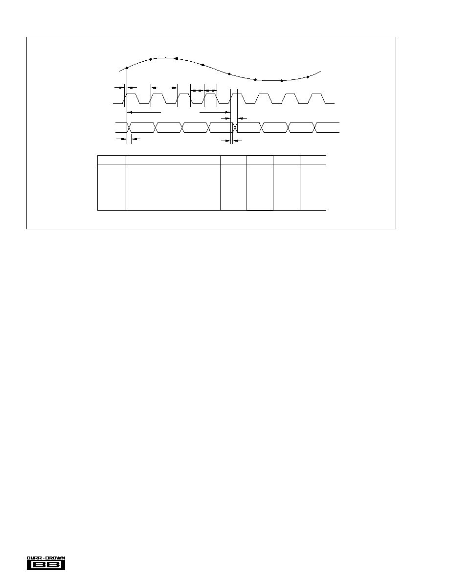
TIMING DIAGRAM
SYMBOL
DESCRIPTION
MIN
TYP
MAX
UNITS
t
CONV
Convert Clock Period
16.6
100
µ
s
ns
t
L
Clock Pulse Low
7.3
8.3
ns
t
H
Clock Pulse High
7.3
8.3
ns
t
D
Aperture Delay
3
ns
t
1
Data Hold Time, C
L
= 0pF
3.9
ns
t
2
New Data Delay Time, C
L
= 15pF max
5.9
12
ns
The information provided herein is believed to be reliable; however, BURR-BROWN assumes no responsibility for inaccuracies or omissions. BURR-BROWN assumes no responsibility
for the use of this information, and all use of such information shall be entirely at the user's own risk. Prices and specifications are subject to change without notice. No patent rights
or licenses to any of the circuits described herein are implied or granted to any third party. BURR-BROWN does not authorize or warrant any BURR-BROWN product for use in life
support devices and/or systems.
4 Clock Cycles
Data Invalid
t
D
t
L
t
H
t
CONV
N≠4
N≠3
N≠2
N≠1
N
N+1
N+2
N+3
Data Out
Clock
Analog In
N
t
2
N+1
N+2
N+3
N+4
N+5
N+6
N+7
t
1

5
Æ
ADS830
SPECTRAL PERFORMANCE
(Single-Ended, 1Vp-p)
Frequency (MHz)
7.5
0
15
22.5
30
Magnitude (dB)
0
≠10
≠20
≠30
≠40
≠50
≠60
≠70
≠80
≠90
f
IN
= 10MHz
SNR = 49dBFS
SFDR = 65dBFS
SPECTRAL PERFORMANCE
Frequency (MHz)
Magnitude (dB)
0
7.5
15
22.5
30
0
≠10
≠20
≠30
≠40
≠50
≠60
≠70
≠80
≠90
f
IN
= 20MHz
SNR = 49dBFS
SFDR = 63dBFS
SPECTRAL PERFORMANCE
Frequency (MHz)
0
7.5
15
22.5
30
Magnitude (dB)
0
≠10
≠20
≠30
≠40
≠50
≠60
≠70
≠80
≠90
f
IN
= 10MHz
SNR = 49dBFS
SFDR = 65dBFS
SPECTRAL PERFORMANCE
Frequency (MHz)
0
7.5
15
22.5
30
Magnitude (dB)
0
≠10
≠20
≠30
≠40
≠50
≠60
≠70
≠80
≠90
f
IN
= 1MHz
SNR = 49dBFS
SFDR = 67dBFS
TWO-TONE INTERMODULATION DISTORTION
Frequency (MHz)
0
7.5
15
22.5
30
Magnitude (dB)
0
≠10
≠20
≠30
≠40
≠50
≠60
≠70
≠80
≠90
f
1
= 9.5MHz at ≠7dBFS
f
2
= 9.9MHz at ≠7dBFS
IMD(3) = ≠60dBc
TYPICAL PERFORMANCE CURVES
At T
A
= full specified temperature range, single-ended input range = 1.5V to 3.5V, sampling rate = 60MHz, and external reference, unless otherwise noted.
DIFFERENTIAL LINEARITY ERROR
Output Code
DLE (LSB)
0.2
0.1
0
≠0.1
≠0.2
0
64
128
192
256
f
IN
= 10MHz

6
Æ
ADS830
TYPICAL PERFORMANCE CURVES
(CONT)
At T
A
= full specified temperature range, single-ended input range = 1.5V to 3.5V, sampling rate = 60MHz, and external reference, unless otherwise noted.
Output Code
DLE (LSB)
0.2
0.1
0
≠0.1
≠0.2
0
64
128
192
256
f
IN
= 20MHz
DIFFERENTIAL LINEARITY ERROR
INTEGRAL LINEARITY ERROR
Output Code
ILE (LSB)
1.0
0.5
0
≠0.5
≠1.0
0
64
128
192
256
f
IN
= 1MHz
DYNAMIC PERFORMANCE vs INPUT FREQUENCY
Frequency (MHz)
SFDR, SNR (dBFS)
70
60
50
40
0.1
1
10
100
SFDR
SNR
POWER DISSIPATION vs TEMPERATURE
Temperature (
∞
C)
220
210
200
190
180
170
160
≠50
≠25
0
25
50
100
75
Power Dissipation (mW)
External Reference
VDRV = +5V
Internal Reference
800k
600k
400k
200k
0
OUTPUT NOISE HISTOGRAM (DC Input)
Counts
N≠2
N≠1
N
N+1
N+2
Output Code

7
Æ
ADS830
APPLICATION INFORMATION
THEORY OF OPERATION
The ADS830 is a high-speed CMOS analog-to-digital con-
verter which employs a pipelined converter architecture
consisting of 6 internal stages. Each stage feeds its data into
the digital error correction logic ensuring excellent differen-
tial linearity and no missing codes at the 8-bit level. The
output data becomes valid on the rising clock edge (see
Timing Diagram). The pipeline architecture results in a data
latency of 4 clock cycles.
The analog input of the ADS830 is a differential track and
hold, see Figure 1. The differential topology along with
tightly matched capacitors produce a high level of ac perfor-
mance while sampling at very high rates.
The ADS830 allows its analog inputs to be driven either
single-ended or differentially. The typical configuration for
the ADS830 is for the single-ended mode in which the input
track and hold performs a single-ended to differential con-
version of the analog input signal.
Both inputs (IN, IN) require external biasing using a com-
mon-mode voltage that is typically at the mid-supply level
(+V
S
/ 2).
The following application discussion focuses on the single-
ended configuration. Typically, its implementation is easier
to achieve and the rated specifications for the ADS830 are
characterized using the single-ended mode of operation.
DRIVING THE ANALOG INPUT
The ADS830 achieves excellent ac performance either in the
single-ended or differential mode of operation. The selection
for the optimum interface configuration will depend on the
individual application requirements and system structure.
For example, communications applications often process a
band of frequencies that does not include DC, whereas in
imaging applications, the previously restored DC level must
be maintained correctly up to the A/D converter. Features on
the ADS830 like the input range select (RSEL pin) or the
option for an external reference provide the needed flexibil-
ity to accommodate a wide range of applications. In any
case, the ADS830 should be configured such that the appli-
cation objectives are met while observing the headroom
requirements of the driving amplifier in order to yield the
best overall performance.
INPUT CONFIGURATIONS
AC-Coupled, Single-Supply Interface
Figure 2 shows the typical circuit for an ac-coupled analog
input configuration of the ADS830 where all components
are powered from a single +5V supply.
With the RSEL pin connected HIGH, the full-scale input
range is set to 2Vp-p. In this configuration, the top and
bottom references (REFT, REFB) provide an output voltage
of +3.0V and +2.0V, respectively. Two resistors ( 2 x 1k
)
are used to create a common-mode voltage (V
CM
) of ap-
proximately +2.5V to bias the inputs of the driving ampli-
fier. Using the OPA681 on a single +5V supply, its ideal
common-mode point is at +2.5V. This coincides with the
recommended common-mode input level for the ADS830
thus, obviating the need for a coupling capacitor between the
amplifier and the converter. Even though the OPA681 has an
ac gain of +2, the dc gain is only +1 due to the blocking
capacitor at resistor R
G
.
The addition of a small series resistor (R
S
) between the
output of the op amp and the input of the ADS830 will be
beneficial in almost all interface configurations. This will
de-couple the op amp's output from the capacitive load and
avoid gain peaking, which can result in increased noise. For
best spurious and distortion performance, the resistor value
should be kept below 75
. The series resistor in combina-
tion with the 47pF capacitor establishes a passive low-pass
filter, limiting the bandwidth for the wideband noise thus
help improving the SNR performance.
AC-Coupled, Dual Supply Interface
The circuit provided in Figure 3 shows typical connections
for the analog input in case the selected amplifier operates
on dual supplies. This might be necessary to take full
advantage of very low distortion operational amplifiers,
such as the OPA642. The advantage is that the driving
amplifier can be operated with a ground referenced bipolar
signal swing. This will keep the distortion performance at its
lowest since the signal range stays within the linear region
of the op amp and sufficient headroom to the supply rails can
be maintained. By capacitively coupling the single-ended
signal to the input of the ADS830, its common-mode re-
quirements can easily be satisfied with two resistors con-
nected between the top and bottom reference.
1
1
2
1
1
1
1
1
2
1
2
1
2
IN
IN
OUT
OUT
Op Amp
Bias
V
CM
Op Amp
Bias
V
CM
C
H
C
I
C
I
C
H
Input Clock (50%)
Internal Non-overlapping Clock
FIGURE 1. Simplified Circuit of Input Track and Hold with
Timing Diagram.

8
Æ
ADS830
OPA642
V
IN
R
F
402
1k
R
G
402
ADS830
R
S
24.9
1k
47pF
0.1µF
0.1
µ
F
IN
IN
CM
REFB
+2.0V
INT/EXT
GND
REFT
+3.0V
RSEL
+V
S
+5V
+5V
≠5V
ately biased using the +2.5V common-mode voltage avail-
able at the CM pin. One-half of the amplifier (OPA2681)
buffers the REFB pin and drives the voltage divider R
1
, R
2
.
Because of the op amp's noise gain of +2V/V, assuming
R
F
= R
IN
, the common-mode voltage (V
CM
) has to be re-
scaled to +1.25V, resulting in the correct DC level of +2.5V
for the signal input (IN). Any DC voltage differences be-
tween the IN and IN inputs of the ADS830 effectively
produce an offset, which can be corrected for by adjusting
the resistor values of the divider, R
1
and R
2
. The selection
criteria for a suitable op amp should include the supply
voltage, input bias current, output voltage swing, distortion
and noise specification. Note that in this example the overall
signal phase is inverted. To re-establish the original signal
polarity, it is always possible to interchange the IN and IN
connections.
FIGURE 3. AC-Coupling the Dual Supply Amplifier OPA642 to the ADS830 for a 2Vp-p Full Scale Input Range.
For applications requiring the driving amplifier to provide a
signal amplification, with a gain
5, consider using decom-
pensated voltage feedback op amps, such as the OPA643, or
current feedback op amps OPA681 and OPA658.
DC-Coupled with Level Shift
Several applications may require that the bandwidth of the
signal path includes DC, in which case the signal has to be
DC-coupled to the A/D converter. In order to accomplish
this, the interface circuit has to provide a DC level shift to
the analog input signal. The circuit shown in Figure 4
employs a dual op amp, A1, to drive the input of the
ADS830 and level shift the signal to be compatible with
the selected input range. With the RSEL pin tied to the
supply and the INT/EXT pin to ground, the ADS830 is
configured for a 2Vp-p input range and uses the internal
references. The complementary input (IN) may be appropri-
+V
IN
0V
≠V
IN
OPA681
V
IN
R
F
402
1k
R
G
402
ADS830
R
S
39
47pF
0.1µF
IN
IN
CM
INT/EXT
GND
REFT
+3.0V
1k
V
CM
= +2.5V
DC
REFB
+2.0V
0.1
µ
F
0.1µF
RSEL
+V
S
+5V
+5V
FIGURE 2. AC-Coupled Input Configuration for a 2Vp-p Full-Scale Range and a Common-Mode Voltage, V
CM
, at +2.5V
Derived from the Internal Top (REFT) and Bottom Reference (REFB). The OPA680 can be used in place of the
OPA681 if a voltage feedback amplifier is preferred.

9
Æ
ADS830
FIGURE 5. Transformer Coupled Input.
FIGURE 6. Equivalent Reference Circuit with Recommended
Reference Bypassing.
V
IN
IN
IN
CM
22
22
47pF
R
T
47pF
+
10µF
0.1µF
INT/EXT
RSEL
+5V
ADS830
1:n
0.1µF
R
G
ADS830
REFT
CM
REFB
Bypass Capacitors: 0.1µF || 2.2µF each
Bandgap Reference and Logic
V
REF
400
400
+1
+1
+V
S
50k
50k
INT/EXT
RSEL
SINGLE-ENDED-TO-DIFFERENTIAL CONFIGURATION
(Transformer Coupled)
If the application requires a signal conversion from a single-
ended source to feed the ADS830 differentially, a RF trans-
former might be a good solution. The selected transformer
must have a center tap in order to apply the common-mode
DC voltage necessary to bias the converter inputs.
AC grounding the center tap will generate the differential
signal swing across the secondary winding. Consider a step-
up transformer to take advantage of a signal amplification
without the introduction of another noise source. Further-
more, the reduced signal swing from the source may lead to
an improved distortion performance.
The differential input configuration may provide a notice-
able advantage of achieving good SFDR performance over
a wide range of input frequencies. In this mode both inputs
of the ADS830 see closely matched impedances, and the
differential signal swing is reduced to half of the swing
required for single-ended drive. Figure 5 shows the sche-
matic for the suggested transformer coupled interface cir-
cuit. The component values of the R-C lowpass may be
optimized depending on the desired roll-off frequency. The
resistor across the secondary side (R
T
) should be calculated
using the equation R
T
= n
2
x R
G
to match the source
impedance (R
G
) for good power transfer and VSWR.
REFERENCE OPERATION
Figure 6 depicts the simplified model of the internal refer-
ence circuit. The internal blocks are the bandgap voltage
reference, the drivers for the top and bottom reference, and
2Vp-p
NOTE: R
F
= R
IN
, G = ≠1
V
IN
R
2
301
R
1
499
ADS830
R
S
39
47pF
0.1µF
IN
IN
CM (+2.5V)
INT/EXT
R
F
499
R
IN
499
V
CM
= +1.25V
REFB
(+2.0V)
REFT
(+3.0V)
1/2
OPA2681
1/2
OPA2681
R
F
1k
50
0.1µF
0.1µF
RSEL
+V
S
+5V
+5V
FIGURE 4. DC-Coupled Interface Circuit with Dual Current-Feedback Amplifier OPA2681. The OPA2680 can be used in place
of the OPA2681 if a voltage feedback amplifier is preferred.

10
Æ
ADS830
REFT
+3.0V
ADS830
CMV
+2.5V
REFB
+2.0V
R
1
1k
R
2
1k
0.1µF
0.1µF
2.2µF
+
2.2µF
+
the resistive reference ladder. The bandgap reference circuit
includes logic functions that allow to set the analog input
swing of the ADS830 to either a 1Vp-p or 2Vp-p full-scale
range simply by tying the RSEL pin to a LOW or HIGH
potential, respectively. While operating the ADS830 in the
external reference mode, the buffer amplifiers for REFT and
REFB are disconnected from the reference ladder.
As shown, the ADS830 has internal 50k
pull-up resistors
at the Range Select pin (RSEL) and Reference Select pin
(INT/EXT). Leaving those pins open configures the ADS830
for a 2Vp-p input range and external reference operation.
Setting the ADS830 up for internal reference mode requires
to bring the INT/EXT pin LOW.
The reference buffers can be utilized to supply up to 1mA
(sink and source) to external circuitry. To ensure proper
operation with any reference configurations, it is necessary
to provide solid bypassing at the reference pins in order to
keep the clock feedthrough to a minimum (Figure 6). All
bypassing capacitors should be located as close to their
respective pins as possible.
FIGURE 8. Configuration Example for External Reference Operation.
The common-mode voltage available at the CM pin may be
used as a bias voltage to provide the appropriate offset for
the driving circuitry. However, care must be taken not to
appreciably load this node, which is not buffered and has a
high impedance. An alternative way of generating a com-
mon-mode voltage is given in Figure 7. Here, two external
precision resistors (1% tolerance or better) are located
between the top and bottom reference pins. The common-
mode voltage, CMV, will appear at the midpoint.
EXTERNAL REFERENCE OPERATION
For even more design flexibility, the internal reference can
be disabled and an external reference voltage be used. The
utilization of an external reference may be considered for
applications requiring higher accuracy, improved tempera-
ture performance, or a wide adjustment range of the
converter's full-scale range. Especially in multichannel
applications, the use of a common external reference has the
benefit of obtaining better matching of the full-scale range
between converters.
The external references can vary as long as the value of the
external top reference REFT
EXT
stays within the range of
(V
S
≠ 1.25V) and (REFB + 0.8V), and the external bottom
reference REFB
EXT
stays within 1.25V and (REFT ≠ 0.8V),
see Figure 8.
The full-scale input signal range (FSR) of the ADS830 is
determined by the voltage difference across the reference
pins REFT and REFB (FSR = REFT ≠ REFB), while the
common-mode voltage is defined by CMV = (REFT +
REFB)/2. In order to maintain good ac performance, it is
recommended that the typical common-mode voltage be
kept at +2.5V while setting the external reference voltages.
It is possible, however, to deviate from this common-mode
level without significantly impacting the performance. In
particular, DC-coupled applications may benefit from a
ADS830
IN
IN
INT/EXT
REFT
GND
REFB
External Top Reference
REFT = REFB +0.8V to +3.75V
+VS
B
A
RSEL
GND
+5V
External Bottom Reference
REFB = REFT ≠0.8V to +1.25V
V
IN
A - Short for 1Vp-p Input Range
B - Short for 2Vp-p Input Range (Default)
CMV
FIGURE 7. Alternative Circuit to Generate Common-Mode
Voltage.

11
Æ
ADS830
lower CMV as it increases the signal headroom of the
driving amplifier. The internal reference ladder has a nomi-
nal impedance of 800
. Depending on the selected refer-
ence voltages, the required drive current will vary accord-
ingly and the external reference circuitry should be designed
to supply the maximum required current.
DIGITAL INPUTS AND OUTPUTS
Clock Input Requirements
Clock jitter is critical to the SNR performance of high speed,
high resolution Analog to Digital Converters. It leads to
aperture jitter (t
A
) which adds noise to the signal being
converted. The ADS830 samples the input signal on the
rising edge of the CLK input. Therefore, this edge should
have the lowest possible jitter. The jitter noise contribution
to total SNR is given by the following equation. If this value
is near your system requirements, input clock jitter must be
reduced.
Where:
IN
is Input Signal Frequency
t
A
is rms Clock Jitter
Particularly in udersampling applications, special consider-
ation should be given to clock jitter. The clock input should
be treated as an analog input in order to achieve the highest
level of performance. Any overshoot or undershoot of the
clock signal may cause degradation of the performance.
When digitizing at high sampling rates, the clock should
have a 50% duty cycle (t
H
= t
L
), along with fast rise and fall
times of 2ns or less.
Digital Outputs
The output data format of the ADS830 is in positive Straight
Offset Binary code, see Table I. This format can easily
converted into the Two's Binary Complement code by
inverting the MSB.
Digital Output Driver (VDRV)
The ADS830 features a dedicated supply pin for the output
logic drivers, VDRV, which is not internally connected to
the other supply pins. Setting the voltage at VDRV to +5V
or +3V, the ADS830 produces corresponding logic levels
and can directly interface to the selected logic family. The
output stages are designed to supply sufficient current to
drive a variety of logic families. However, it is recom-
mended to use the ADS830 with +3V logic supply. This will
lower the power dissipation in the output stages due to the
lower output swing and reduce current glitches on the supply
line which may affect the ac performance of the converter.
In some applications, it might be advantageous to decouple
the VDRV pin with additional capacitors or a pi-filter.
GROUNDING AND DECOUPLING
Proper grounding and bypassing, short lead length, and the
use of ground planes are particularly important for high
frequency designs. Multilayer PC boards are recommended
for best performance since they offer distinct advantages
like minimizing ground impedance, separation of signal
layers by ground layers, etc. The ADS830 should be treated
as an analog component. Whenever possible, the supply pins
should be powered by the analog supply. This will ensure
the most consistent results, since digital supply lines often
carry high levels of noise which otherwise would be coupled
into the converter and degrade the achievable performance.
All ground connections on the ADS830 are internally joined
together, obviating the design of split ground planes. The
ground pins (1, 18) should directly connect to an analog
ground plane which covers the PC board area around the
converter. While designing the layout, it is important to keep
the analog signal traces separated from any digital lines to
prevent noise coupling onto the analog signal path. Because
of its high sampling rate, the ADS830 generates high fre-
quency current transients and noise (clock feedthrough) that
are fed back into the supply and reference lines. This
requires that all supply and reference pins are sufficiently
bypassed. Figure 9 shows the recommended decoupling
scheme for the ADS830. In most cases 0.1
µ
F ceramic chip
capacitors at each pin are adequate to keep the impedance
low over a wide frequency range. Their effectiveness largely
depends on the proximity to the individual supply pin.
Therefore, they should be located as close to the supply pins
as possible. In addition, a larger bipolar capacitor (1
µ
F to
22
µ
F) should be placed on the PC board in proximity of the
converter circuit.
It is recommended to keep the capacitive loading on the data
lines as low as possible (
15pF). Higher capacitive loading
will cause larger dynamic currents as the digital outputs are
changing. Those high current surges can feed back to the
analog portion of the ADS830 and affect the performance. If
necessary, external buffers or latches close to the converter's
output pins may be used to minimize the capacitive loading.
They also provide the added benefit of isolating the ADS830
from any digital noise activities on the bus coupling back
high frequency noise.
FIGURE 9. Recommended Bypassing for the Supply Pins.
1
GND
ADS830
+
0.1µF
+V
S
19
18
GND
10µF
+5V
VDRV
20
0.1µF
+3/+5V
Jitter SNR
t
rms signal to rms noise
IN A
=
20
1
2
log
+FS (IN = +3.5V)
1111 1111
+1/2 FS
1100 0000
+1LSB
1000 0001
Bipolar Zero (IN = 2.5V)
1000 0000
≠1LSB
0111 1111
≠1/2 FS
0100 0000
≠FS (IN = +1.5V)
0000 0000
SINGLE-ENDED INPUT (2Vp-p)
STRAIGHT OFFSET BINARY
(IN = CMV)
(SOB)
TABLE I. Coding Table for the ADS830.