 | –≠–ª–µ–∫—Ç—Ä–æ–Ω–Ω—ã–π –∫–æ–º–ø–æ–Ω–µ–Ω—Ç: INA110 | –°–∫–∞—á–∞—Ç—å:  PDF PDF  ZIP ZIP |

INA110
Fast-Settling FET-Input
INSTRUMENTATION AMPLIFIER
APPLICATIONS
q
MULTIPLEXED INPUT DATA
ACQUISITION SYSTEM
q
FAST DIFFERENTIAL PULSE AMPLIFIER
q
HIGH SPEED GAIN BLOCK
q
AMPLIFICATION OF HIGH IMPEDANCE
SOURCES
DESCRIPTION
The INA110 is a versatile monolithic FET-input
instrumentation amplifier. Its current-feedback circuit
topology and laser trimmed input stage provide
excellent dynamic performance and accuracy. The
INA110 settles in 4
µ
s to 0.01%, making it ideal for
high speed or multiplexed-input data acquisition
systems.
Internal gain-set resistors are provided for gains of 1,
10, 100, 200, and 500V/V. Inputs are protected for
differential and common-mode voltages up to
±
V
CC
.
Its very high input impedance and low input bias
current make the INA110 ideal for applications
requiring input filters or input protection circuitry.
The INA110 is available in 16-pin plastic and ceramic
DIPs, and in the SOL-16 surface-mount package.
Military, industrial and commercial temperature range
grades are available.
A
1
1
404
4.44k
201
80.2
A
2
20k
10k
10k
20k
A
3
10k
10k
13
12
16
11
3
2
4
5
8
7
14
15
9
6
10
≠In
X
10
X
100
X
200
X
500
R
G
+In
(1)
Output
Ref
Sense
+V
CC
≠V
CC
Input
Offset
Adjust
Output
Offset
Adjust
FET
Input
FET
Input
INA110
NOTE: (1) Connect to R
G
for desired gain.
International Airport Industrial Park ∑ Mailing Address: PO Box 11400 ∑ Tucson, AZ 85734 ∑ Street Address: 6730 S. Tucson Blvd. ∑ Tucson, AZ 85706
Tel: (520) 746-1111 ∑ Twx: 910-952-1111 ∑ Cable: BBRCORP ∑ Telex: 066-6491 ∑ FAX: (520) 889-1510 ∑ Immediate Product Info: (800) 548-6132
Æ
FEATURES
q
LOW BIAS CURRENT: 50pA max
q
FAST SETTLING: 4
µ
s to 0.01%
q
HIGH CMR: 106dB min; 90dB at 10kHz
q
INTERNAL GAINS: 1, 10, 100, 200, 500
q
VERY LOW GAIN DRIFT: 10 to 50ppm/
∞
C
q
LOW OFFSET DRIFT: 2
µ
V/
∞
C
q
LOW COST
q
PINOUT SIMILAR TO AD524 AND AD624
©
1986 Burr-Brown Corporation
PDS-645E
Printed in U.S.A. September, 1993

Æ
INA110
2
SPECIFICATIONS
ELECTRICAL
At +25
∞
C,
±
V
CC
=
15VDC, and R
L
= 2k
, unless otherwise specified.
INA110BG, SG
INA110KP, KU
INA110AG
G = 1 + [40k/(R
G
+ 50
)]
PARAMETER
CONDITIONS
MIN
TYP
MAX
MIN
TYP
MAX
MIN
TYP
MAX
UNITS
GAIN
Range of Gain
1
800
*
*
*
*
V/V
Gain Equation
(1)
*
*
V/V
Gain Error, DC: G = 1
0.002
0.04
*
0.02
*
*
%
G = 10
0.01
0.1
0.005
0.05
*
*
%
G = 100
0.02
0.2
0.01
0.1
*
*
%
G = 200
0.04
0.4
0.02
0.2
*
*
%
G = 500
0.1
1
0.05
0.5
*
*
%
Gain Temp. Coefficient: G = 1
±
3
±
20
*
±
10
*
ppm/
∞
C
G = 10
±
4
±
20
±
2
±
10
*
ppm/
∞
C
G = 100
±
6
±
40
±
3
±
20
*
ppm/
∞
C
G = 200
±
10
±
60
±
5
±
30
*
ppm/
∞
C
G = 500
±
25
±
100
±
10
±
50
*
ppm/
∞
C
Nonlinearity, DC: G = 1
±
0.001
±
0.01
±
0.0005
±
0.005
*
*
% of FS
G = 10
±
0.002
±
0.01
±
0.001
±
0.005
*
*
% of FS
G = 100
±
0.004
±
0.02
±
0.002
±
0.01
*
*
% of FS
G = 200
±
0.006
±
0.02
±
0.003
±
0.01
*
*
% of FS
G = 500
±
0.01
±
0.04
±
0.005
±
0.02
*
*
% of FS
OUTPUT
Voltage, R
L
= 2k
Over Temperature
±
10
±
12.7
*
*
*
*
V
Current
Over Temperature
±
5
±
25
*
*
*
*
mA
Short-Circuit Current
±
25
*
*
mA
Capacitive Load
Stability
5000
*
*
pF
INPUT OFFSET VOLTAGE
(2)
Initial Offset: G, P
±
(100 +
±
(500 +
±
(50 +
±
(250 +
*
*
µ
V
1000/G) 5000/G)
600/G)
3000/G)
U
±
(200 +
±
(1000 +
µ
V
2000/G) 5000/G)
vs Temperature
±
(2 +
±
(5 +
±
(1 +
±
(2 +
*
µ
V/
∞
C
20/G)
100/G)
10/G)
50/G)
vs Supply
V
CC
=
±
6V to
±
18V
±
(4 +
±
(30 +
±
(2 +
±
(10 +
*
*
µ
V/V
60/G)
300/G)
30/G)
180/G)
BIAS CURRENT
Initial Bias Current
Each Input
20
100
10
50
*
*
pA
Initial Offset Current
2
50
1
25
*
*
pA
Impedance: Differential
5x10
12
||6
*
*
|| pF
Common-Mode
2x10
12
||1
*
*
|| pF
VOLTAGE RANGE
V
IN
Diff. = 0V
(3)
Range, Linear Response
±
10
±
12
*
*
V
CMR with 1k
Source Imbalance:
G = 1
DC
70
90
80
100
*
*
dB
G = 10
DC
87
104
96
112
*
*
dB
G = 100
DC
100
110
106
116
*
*
dB
G = 200
DC
100
110
106
116
*
*
dB
G = 500
DC
100
110
106
116
*
*
dB
INPUT NOISE
(4)
Voltage, f
O
= 10kHz
10
*
*
nV/
Hz
f
B
= 0.1Hz to 10Hz
1
*
*
µ
Vp-p
Current, f
O
= 10kHz
1.8
*
*
fA/
Hz
OUTPUT NOISE
(4)
Voltage, f
O
= 10kHz
65
*
*
nV/
Hz
f
B
= 0.1Hz to 10Hz
8
*
*
µ
Vp-p
DYNAMIC RESPONSE
Small Signal: G = 1
≠3dB
2.5
*
*
MHz
G = 10
2.5
*
*
MHz
G = 100
470
*
*
kHz
G = 200
240
*
*
kHz
G = 500
100
*
*
kHz
Full Power
V
OUT
=
±
10V,
G = 2 to 100
190
270
*
*
*
*
kHz
Slew Rate
G = 2 to 100
12
17
*
*
*
*
V/
µ
s
Settling Time:
0.1%, G = 1
V
O
= 20V Step
4
*
*
µ
s
G = 10
2
*
*
µ
s
G = 100
3
*
*
µ
s
G = 200
5
*
*
µ
s
G = 500
11
*
*
µ
s

Æ
INA110
3
PARAMETER
CONDITIONS
MIN
TYP
MAX
MIN
TYP
MAX
MIN
TYP
MAX
UNITS
DYNAMIC RESPONSE (CONT)
Settling Time:
0.01%,G = 1
V
O
= 20V Step
5
12.5
*
*
*
µ
s
G = 10
3
7.5
*
*
*
µ
s
G = 100
4
7.5
*
*
*
µ
s
G = 200
7
12.5
*
*
*
µ
s
G = 500
16
25
*
*
*
µ
s
Recovery
(5)
50% Overdrive
1
*
*
µ
s
POWER SUPPLY
Rated Voltage
±
15
*
*
V
Voltage Range
±
6
±
18
*
*
*
*
V
Quiescent Current
V
O
= 0V
±
3
±
4.5
*
*
*
*
mA
TEMPERATURE RANGE
Specification: A, B, K
≠25
+85
*
*
0
+70
∞
C
S
≠55
+125
∞
C
Operation
≠55
+125
*
*
≠25
+85
∞
C
Storage
≠65
+150
*
*
≠40
+85
∞
C
JA
100
*
*
∞
C/W
SPECIFICATIONS
(CONT)
ELECTRICAL
At +25
∞
C,
±
V
CC
15VDC, and R
L
= 2K
, unless otherwise specified.
INA110BG, SG
INA110KP, KU
INA110AG
* Same as INA110AG.
NOTES: (1) Gains other than 1, 10, 100, 200, and 500 can be set by adding an external resistor, R
G
, between pin 3 and pins 11, 12 and 16. Gain accuracy is a function
of R
G
and the internal resistors which have a
±
20% tolerance with 20ppm/
∞
C drift. (2) Adjustable to zero. (3) For differential input voltage other than zero, see Typical
Performance Curves. (4) V
NOISE RTI
=
V
N
2
INPUT
+ (V
N OUTPUT
/Gain)
2
. (5) Time required for output to return from saturation to linear operation following the removal of
an input overdrive voltage.
ABSOLUTE MAXIMUM RATINGS
Supply Voltage ..................................................................................
±
18V
Input Voltage Range ..........................................................................
±
V
CC
Operating Temperature Range: G ................................. ≠55
∞
C to +125
∞
C
P, U ............................... ≠25
∞
C to +85
∞
C
Storage Temperature Range: G .................................... ≠65
∞
C to +150
∞
C
P, U .................................. ≠40
∞
C to +85
∞
C
Lead Temperature (soldering, 10s): G, P ..................................... +300
∞
C
(soldering, 3s): U ........................................... +260
∞
C
Output Short Circuit Duration ............................... Continuous to Common
PACKAGE INFORMATION
PACKAGE DRAWING
MODEL
PACKAGE
NUMBER
(1)
INA110AG
16-Pin Ceramic DIP
109
INA110BG
16-Pin Ceramic DIP
109
INA110SG
16-Pin Ceramic DIP
109
INA110KP
16-Pin Plastic DIP
180
INA110KU
SOL-16 SOIC
211
NOTE: (1) For detailed drawing and dimension table, please see end of data
sheet, or Appendix D of Burr-Brown IC Data Book.
Top View
DIP/SOIC
PIN CONFIGURATION
ORDERING INFORMATION
MODEL
PACKAGE
TEMPERATURE RANGE
INA110AG
16-Pin Ceramic DIP
≠25
∞
C to +85
∞
C
INA110BG
16-Pin Ceramic DIP
≠25
∞
C to +85
∞
C
INA110SG
16-Pin Ceramic DIP
≠55
∞
C to +125
∞
C
INA110KP
16-Pin Plastic DIP
0
∞
C to +70
∞
C
INA110KU
SOL-16 SOIC
0
∞
C to +70
∞
C
The information provided herein is believed to be reliable; however, BURR-BROWN assumes no responsibility for inaccuracies or omissions. BURR-BROWN
assumes no responsibility for the use of this information, and all use of such information shall be entirely at the user's own risk. Prices and specifications are subject
to change without notice. No patent rights or licenses to any of the circuits described herein are implied or granted to any third party. BURR-BROWN does not
authorize or warrant any BURR-BROWN product for use in life support devices and/or systems.
≠In
+In
R
G
Input Offset Adj.
Input Offset Adj.
Reference
≠V
CC
+V
CC
x200
Output Offset Adj.
Output Offset Adj.
x10
x100
x500
Output Sense
Output
1
2
3
4
5
6
7
8
16
15
14
13
12
11
10
9

Æ
INA110
4
0
Load Resistance (
)
OUTPUT SWING vs LOAD RESISTANCE
Output Voltage (V)
±16
±12
±8
±4
400
1.6k
0
2M
800
1.2k
±4
Power Supply Voltage (V)
OUTPUT SWING vs SUPPLY
Output Voltage (V)
±16
±13
±10
±7
R
L
= 2k
±9
±15
±6
±18
±12
±3
Power Supply Voltage (V)
INPUT VOLTAGE RANGE vs SUPPLY
Input Voltage Range (V)
±9
±15
±6
±18
±15
±12
±9
±6
±12
0
Power Supply Voltage (V)
BIAS CURRENT vs SUPPLY
Input Bias Current (pA)
±9
±15
±6
±18
25
20
15
10
5
±12
DICE INFORMATION
PAD
FUNCTION
1
≠In
2
+In
3A,3B
R
G
(connect both)
4
Input Offset Adjust
5
Input Offset Adjust
6
Reference
7
≠V
CC
8
+V
CC
9
Output
10
Output Sense
11
x500
12
x100
13
x10
14
Output Offset Adjust
15
Output Offset Adjust
16
x200
Pads 3A and 3B must be connected.
Substrate Bias: Internally connected to ≠V
CC
power sup-
ply.
MECHANICAL INFORMATION
MILS (0.001")
MILLIMETERS
Die Size
139 x 89
±
5
3.53 x 2.26
±
0.13
Die Thickness
20
±
3
0.51
±
0.08
Min. Pad Size
4 x 4
0.10 x 0.10
Backing
Gold
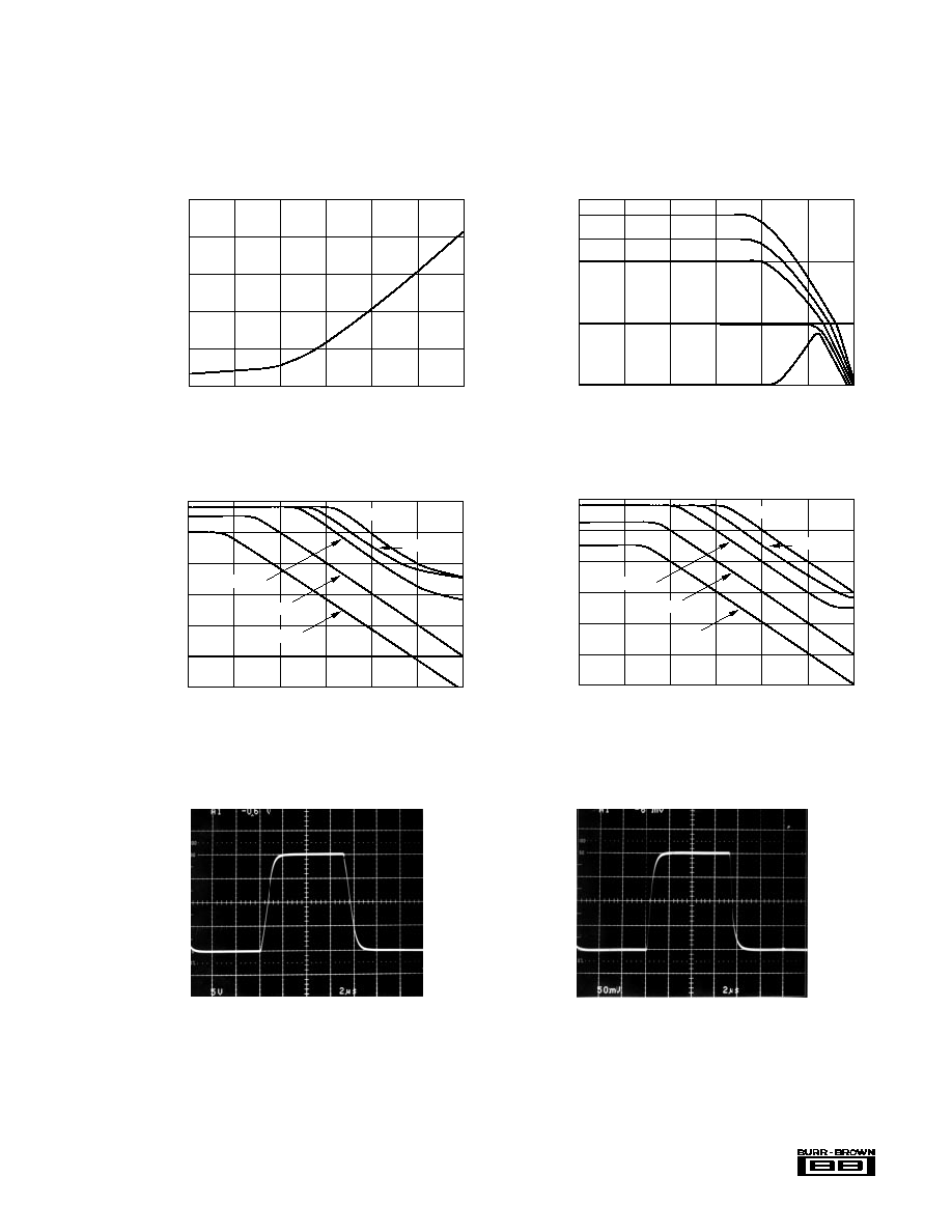
TYPICAL PERFORMANCE CURVES
At T
A
= +25
∞
C, and
±
V
CC
= 15VDC, unless otherwise noted.
INA110 DIE TOPOGRAPHY
15
14
13
12
11
10
9
8
7
7
6
5
4
3A
2
1
16
3B
Æ
INA110
5
0
Frequency (Hz)
POWER SUPPLY REJECTION vs FREQUENCY
1
120
100
80
60
40
20
10
100
1k
10k
100k
1M
Power Supply Rejection (dB)
G = 500
G = 200
G = 100
G = 10
G = 1
0
Frequency (Hz)
CMR vs FREQUENCY
1
120
100
80
60
40
20
10
100
1k
10k
100k
1M
Common-Mode Rejection (dB)
G = 500
G = 200
G = 100
G = 10
G = 1
1
Frequency (Hz)
GAIN vs FREQUENCY
10
1k
100
10
100
1k
10k
100k
1M
10M
Gain (V/V)
G = 500
G = 200
G = 100
G = 10
G = 1
1pA
Temperature (∞C)
BIAS CURRENT vs TEMPERATURE
≠55
100nA
10nA
1pA
100pA
10pA
≠25
5
35
65
95
125
Input Bias Current
TYPICAL PERFORMANCE CURVES
(CONT)
T
A
= +25
∞
C,
±
V
CC
= 15VDC, unless otherwise noted.
Time (µs)
SMALL SIGNAL TRANSIENT RESPONSE
(G = 100)
10
Output Voltage (V)
100
0
≠100
0
20
Time (µs)
LARGE SIGNAL TRANSIENT RESPONSE
(G = 100)
10
Output Voltage (V)
10
0
≠10
0
20

Æ
INA110
6
0
Differential Input Voltage x Gain (V) = V
O
COMMON-MODE VOLTAGE vs
DIFFERENTIAL INPUT VOLTAGE
Common-Mode Voltage (V)
12
9
6
3
3
9
0
12
6
INPUT NOISE VOLTAGE vs FREQUENCY
Input Noise Voltage (nV/
Hz)
100
50
20
10
5
2
1
Frequency (Hz)
10
1k
1
10k
100
OUTPUT NOISE VOLTAGE vs FREQUENCY
Output Noise Voltage (nV/
Hz)
1000
500
200
100
50
20
10
Frequency (Hz)
10
1k
1
10k
100
0
Gain (V/V)
SETTLING TIME vs GAIN
(0.01%, 20V Step)
Settling Time (µs)
100
1
1k
20
15
10
5
10
TYPICAL PERFORMANCE CURVES
(CONT)
T
A
= +25
∞
C,
±
V
CC
= 15VDC, unless otherwise noted.
0
Time (minutes)
WARM-UP DRIFT vs TIME
Change In Input Offset Voltage (µV)
50
40
30
20
10
1
4
0
5
2
3

Æ
INA110
7
DISCUSSION OF
PERFORMANCE
A simplified diagram of the INA110 is shown on the first
page. The design consists of the classical three operational
amplifier configuration using current-feedback type op amps
with precision FET buffers on the input. The result is an
instrumentation amplifier with premium performance not
normally found in integrated circuits.
The input section (A
1
and A
2
) incorporates high perfor-
mance, low bias current, and low drift amplifier circuitry.
The amplifiers are connected in the noninverting configura-
tion to provide high input impedance (10
12
). Laser-trim-
ming is used to achieve low offset voltage. Input cascoding
assures low bias current and high CMR. Thin-film resistors
on the integrated circuit provide excellent gain accuracy and
temperature stability.
The output section (A
3
) is connected in a unity-gain differ-
ence amplifier configuration. Precision matching of the four
10
k
resistors, especially over temperature and time,
assures high common-mode rejection.
BASIC POWER SUPPLY
AND SIGNAL CONNECTIONS
Figure 1 shows the proper connections for power supply and
signal. Supplies should be decoupled with 1
µ
F tantalum
capacitors as close to the amplifier as possible. To avoid
gain and CMR errors introduced by the external circuit,
connect grounds as indicated, being sure to minimize ground
resistance. Resistance in series with the reference (pin 6)
will degrade CMR. To maintain stability, avoid capacitance
from the output to the gain set, offset adjust, and input pins.
INA110's input (RTI) is the offset of the input stage plus
the offset of the output stage divided by the gain of the
input stage. This allows specification of offset independent
of gain.
FIGURE 2. Offset Adjustment Circuit.
1
2
6
10
INA110
9
V
OUT
100k
4
≠V
CC
5
14
15
100k
+V
CC
Input
Offset
Adjust
Output
Offset
Adjust
V
IN
For systems using computer autozeroing techniques, neither
offset nor offset drift are of concern. In many other applica-
tions, the factory-trimmed offset gives excellent results.
When greater accuracy is desired, one adjustment is usually
sufficient. In high gains (>100) adjust only the input offset,
and in low gains the output offset. For higher precision in all
gains, both can be adjusted by first selecting high gain and
adjusting input offset and then low gain and adjusting output
offset. The offset adjustment will, however, add to the drift
by approximately 0.33
µ
V/
∞
C per 100
µ
V of input offset
voltage that is adjusted. Therefore, care should be taken
when considering use of adjustment.
Output offsetting can be accomplished as shown in Figure 3
by applying a voltage to the reference (pin 6) through a
buffer. This limits the resistance in series with pin 6 to
minimize CMR error. Be certain to keep this resistance low.
Note that the offset error can be adjusted at this reference
point with no appreciable degradation in offset drift.
FIGURE 3. Output Offsetting.
1
6
10
INA110
9
V
OUT
R
3
OPA177
V
IN
V
OUT
= V
OFFSETTING
+
V
IN
G.
R
2
R
1
+V
CC
≠V
CC
V
OFFSETTING
V
OFFSETTING
With ±V
CC
= 15V, R
1
= 100k
, R
2
= 1M
.
R
3
= 10k
, V
OFFSETTING
= ±150mV
.
2
OFFSET ADJUSTMENT
Figure 2 shows the offset adjustment circuit for the INA110.
Both the offset of the input stage and output stage can be
adjusted separately. Notice that the offset referred to the
FIGURE 1. Basic Circuit Connection.
1
13
12
16
11
3
2
8
6
10
9
V
OUT
V
IN
x10
x100
x200
x500
7
1µF
R
L
≠V
CC
1µF
+V
CC
Sense
V
OUT
=
V
IN
G
INA110

Æ
INA110
8
GAIN SELECTION
Gain selection is accomplished by connecting the appropri-
ate pins together on the INA110. Table I shows possible
gains from the internal resistors. Keep the connections as
short as possible to maintain accuracy.
Gains other than 1, 10, 100, 200, and 500 can be set by
adding an external resistor, R
G
, between pin 3 and pins 12,
16, and 11. Gain accuracy is a function of R
G
and the
internal resistors which have a
±
20% tolerance with
20ppm/
∞
C drift. The equation for choosing R
G
is shown
below.
Gain can also be changed in the output stage by adding
resistance to the feedback loop shown in Figure 4. This is
useful for increasing the total gain or reducing the input
stage gain to prevent saturation of input amplifiers.
The output gain can be changed as shown in Table II.
Matching of R
1
and R
3
is required to maintain high CMR. R
2
sets the gain with no effect on CMR.
CONNECT PIN 3
GAIN
GAIN
GAIN
TO PIN
ACCURACY (%)
DRIFT (ppm/
∞
C)
The following gains have guaranteed accuracy:
1
none
0.02
10
10
13
0.05
10
100
12
0.1
20
200
16
0.2
30
500
11
0.5
50
The following gains have typical accuracy as shown:
300
12, 16
0.25
10
600
11, 12
0.25
40
700
11, 16
2
40
800
11, 12, 16
2
80
TABLE I. Internal Gain Connections.
are eliminated since they are inside the feedback loop.
Proper connection is shown in Figure 1. When more current
is to be supplied, a power booster can be placed within the
feedback loop as shown in Figure 5. Buffer errors are
minimized by the loop gain of the output amplifier.
FIGURE 4. Gain Adjustment of Output Stage Using H Pad
Attenuator.
FIGURE 5. Current Boosting the Output.
3553
1
6
10
INA110
9
V
OUT
R
L
V
IN
2
I
L
= 100mA
Sense
G ≠1
40k
R
G
= ≠ 50
OUTPUT STAGE GAIN
R
1
AND R
3
R
2
2
1.2k
2.74k
5
1k
511
10
1.5k
340
TABLE II. Output Stage Gain Control.
COMMON-MODE INPUT RANGE
It is important not to exceed the input amplifiers' dynamic
range (see Typical Performance Curves). The differential
input signal and its associated common-mode voltage should
not cause the output of A
1
and A
2
(input amplifiers) to
exceed approximately
±
10V with
±
15V supplies or nonlin-
ear operation will result. Such large common-mode volt-
ages, when the INA110 is in high gain, can cause saturation
of the input stage even though the differential input is very
small. This can be avoided by reducing the input stage gain
and increasing the output stage gain with an H pad attenuator
(see Figure 4).
OUTPUT SENSE
An output sense has been provided to allow greater accuracy
in connecting the load. By attaching this feedback point to
the load at the load site, IR drops due to load currents that
LOW BIAS CURRENT
OF FET INPUT ELIMINATES DC ERRORS
Because the INA110 has FET inputs, bias currents drawn
through input source resistors have a negligible effect on DC
accuracy. The picoamp levels produce no more than micro-
volts through megohm sources. Thus, input filtering and
input series protection are readily achievable.
A return path for the input bias currents must always be
provided to prevent charging of stray capacitance. Other-
wise, the output can wander and saturate. A 1M
to 10M
resistor from the input to common will return floating
sources such as transformers, thermocouples, and
AC-coupled inputs (see Applications section).
DYNAMIC PERFORMANCE
The INA110 is a fast-settling FET input instrumentation
amplifier. Therefore, careful attention to minimize stray
capacitance is necessary to achieve specified performance.
High source resistance will interact with input capacitance to
reduce the overall bandwidth. Also, to maintain stability,
avoid capacitance from the output to the gain set, offset
adjust, and input pins.
Applications with balanced-source impedance will provide
the best performance. In some applications, mismatched
source impedances may be required. If the impedance in the
1
6
10
INA110
9
V
OUT
R
3
V
IN
R
2
2
R
1
Output Stage Gain
=
(R
2
|| 20k
) + R
1
+ R
3
R
2
|| 20k

Æ
INA110
9
negative input exceeds that in the positive input, stray
capacitance from the output will create a net negative feed-
back and improve the circuit stability. If the impedance in
the positive input is greater, the feedback due to stray
capacitance will be positive and instability may result. The
degree of positive feedback depends upon source impedance
imbalance, operating gain, and board layout. The addition of
a small bypass capacitor of 5pF to 50pF directly between the
inputs of the IA will generally eliminate any positive feed-
back. CMR errors due to the input impedance mismatch will
also be reduced by the capacitor.
The INA110 is designed for fast settling with easy gain
selection. It has especially excellent settling in high gain. It
can also be used in fast-settling unity-gain applications. As
with all such amplifiers, the INA110 does exhibit significant
gain peaking when set to a gain of 1. It is, however,
unconditionally stable. The gain peaking can be cancelled
by band-limiting the negative input to 400kHz with a simple
external RC circuit for applications requiring flat response.
CMR is not affected by the addition of the 400kHz RC in a
gain of 1.
Another distinct advantage of the INA110 is the high fre-
quency CMR response. High frequency noise and sharp
common-mode transients will be rejected. To preserve AC
CMR, be sure to minimize stray capacitance on the input
lines. Matching the RCs in the two inputs will help to
maintain high AC CMR.
APPLICATIONS
In addition to general purpose uses, the INA110 is designed
to accurately handle two important and demanding applica-
tions: (1) inputs with high source impedances such as
capacitance/crystal/photodetector sensors and low-pass
filters and series-input protection devices, and (2) rapid-
scanning data acquisition systems requiring fast settling
time. Because the user has access to the output sense, current
sources can also be constructed using a minimum of external
components. Figures 6 through 19 show application circuits.
FIGURE 6. Transformer-Coupled Amplifier.
FIGURE 7. Floating Source Instrumentation Amplifier.
FIGURE 8. Instrumentation Amplifier with Shield Driver.
X
100
3
12
1
2
6
10
INA110
9
V
OUT
1M
Thermocouple
Transducer or
Other Floating
Source
7
8
+15V
≠15V
X200
3
16
1
2
6
10
INA110
9
V
OUT
100
≠15V
7
8
+15V
OPA121
V
IN
Divider minimizes degredation of CMR due to
distributed capacitance on the input lines.
3
16
1
2
6
10
INA110
9
V
OUT
≠15V
7
8
+15V
X200
Transducer

Æ
INA110
10
3
13
1
2
6
10
INA110
9
V
OUT
≠15V
7
8
+15V
X10
SHC5320
In 1
In 2
In 15
In 16
1
8
B-B
MPC800
FIGURE 9. Bridge Amplifier with 1Hz Low-Pass Input Filter.
FIGURE 10. AC-Coupled Differential Amplifier for
Frequencies Greater Than 0.016Hz.
X100
3
12
1
2
6
10
INA110
9
V
OUT
10M
≠15V
100mVp-p
1µF
10M
1µF
7
8
+15V
FIGURE 12. Rapid-Scanning-Rate Data Acquisition Channel
with 5
µ
s Settling to 0.01%.
FIGURE 11. Programmable-Gain Instrumentation Amplifier
(Precision Noninverting or Inverting Buffer with
Gain).
1
13
12
16
11
3
2
6
10
8
9
V
OUT
≠15V
V
IN
X10
X100
X200
X500
Decoder/
Latch/Driver
A
0
A
1
A
2
NOTE: Use manual switch or low resistance relay.
Layout is critical (see section on Dynamic Performance).
7
+15V
FIGURE 13. 60Hz Input Notch Filter.
X10
3
13
1
2
6
10
INA110
9
V
OUT
≠15V
5.34M
(1)
NOTE: (1) For 50Hz use 3.16M
and 6.37M
.
2k
potentiometer sets Q.
7
8
+15V
V
IN
2k
5.34M
(1)
1000pF
500pF
500pF
2.67M
(1)
300
3
11
1
2
6
10
INA110
9
V
OUT
75k
(1)
≠15V
7
8
+15V
NOTE: (1) Larger resistors and a smaller capacitor can be used.
1µF
(1)
X500
75k
(1)
FET input allows low-pass filtering with minimal effect on DC accuracy.
V
REF

Æ
INA110
11
FIGURE 14. Input-Protected Instrumentation Amplifier.
FIGURE 15. High Common-Mode Voltage Differential
Amplifier.
FIGURE 17. Differential Input FET Buffered Current
Source.
FIGURE 18. Differential Input/Differential Output
Amplifier.
6
10
8
9
V
OUT
7
+15V
≠15V
1
13
12
16
11
3
2
X10
X100
X200
X500
R
G
6
10
8
9
V
IN
7
1
13
12
16
11
3
2
X10
X100
X200
X500
R
G
+
≠
INA110
INA110
3
16
1
2
6
10
INA110
9
V
OUT
R
2
≠15V
7
8
+15V
X200
R
1
V
2
D
3
D
4
D
1
D
2
≠15V
+15V
+15V
≠15V
V
1
V
IN
For lower voltage, lower resistor noise:
R
1
= R
2
= 20k
, D
1
≠ D
4
= FDH300 (1nA leakage)
For higher voltage, higher resistor noise:
R
1
= R
2
= 100k
, D
1
≠ D
4
= 2N4117A (1pA leakage)
Matching of RCs on inputs will affect CMR, but
can be optimized by trimming R
1
or R
2
.
FIGURE 16. Digitally-Controlled Fast-Settling Programmable Gain Instrumentation Amplifier.
CODE
GAIN
TYPICAL 0.01% SETTLING TIME
00
10
6
µ
s
01
100
6
µ
s
10
1000
12
µ
s
3
13
1
2
6
10
INA110
9
V
OUT
≠15V
7
8
+15V
X10
V
IN
8
6
2
15
PGA102
X
10
1
16
+15V
7
≠15V
13
4
3
X
100
PGA Gain
Select
R
G
X100
3
12
1
2
6
10
INA110
9
V
OUT
10k
≠15V
10k
7
8
+15V
990k
990k
V
IN
V
2
V
1
Common-mode range = ±1000V.
CMR is dependent on ratio matching
of external input resistors.
Overall G = 1
1
13
12
16
11
3
2
6
10
9
I
OUT
V
IN
X10
X100
X200
X500
R
R
G
≠15V
7
8
+15V
1k
+15V
2N2222A
R
R
L
I
OUT
= (
V
IN
) (G) (1/10k + 1/R)
For 0mA to 20mA output, R = 50.25
with (
V
IN
) (G) = 1V
INA110