
FEATURES
q
COMPLETE 12-BIT DATA ACQUISITION
SYSTEM IN A MINIATURE PACKAGE
q
INPUT RANGES SELECTABLE FOR
UNIPOLAR OR BIPOLAR OPERATION
q
THROUGHPUT RATES:
862/3
872/3
8-BIT ACCURACY:
45kHz
67kHz
12-BIT ACCURACY:
33kHz
50kHz
q
SELECTABLE GAINS OF 1, 10, AND 100
q
FULL MICROPROCESSOR COMPATIBLE
INTERFACE
q
GUARANTEED NO MISSING CODES OVER
TEMPERATURE
q
SURFACE-MOUNT OR PIN GRID ARRAY
PACKAGE OPTIONS
q
HIGH RELIABILITY SCREENED VERSIONS
AVAILABLE
q
FULL SPECIFICATION OVER THREE
TEMPERATURE RANGES:
0 to +70
�
C, �25 to +85
�
C, �55 to +125
�
C
q
EVERY UNIT SUPPLIED WITH
ELECTRICAL TEST DATA
APPLICATIONS
q
INDUSTRIAL PROCESS MONITORING
q
AIRBORNE SYSTEMS MONITORING
q
ENGINE MONITORING
FPO
43%
q
POWER PLANT MONITORING
q
SECURITY SYSTEMS MONITORING
q
AUTOMATIC TEST EQUIPMENT
DESCRIPTION
16 Single-Ended Inputs: SDM862
SDM872
8 Differential Inputs:
SDM863
SDM873
33kHz Throughput Rate: SDM862
SDM863
50kHz Throughput Rate: SDM872
SDM873
The SDM components are complete, pin-compatible,
data acquisition systems housed in a hermetically sealed
1"-square leadless chip carrier or a 1.1"-square pin grid
array. The small package outlines and low power con-
sumption provide an ideal data acquisition solution
when space is at a premium.
The devices comprise of an input multiplexer, instru-
mentation amplifier with selectable gains, sample/hold
amplifier and A/D converter with microprocessor inter-
face and three-state buffers.
The SDM family will accept unipolar or bipolar voltage
inputs in the range 0 to +10V,
�
5V and
�
10V. For low-
level signals, jumper-selectable gains of 10 or 100 can
be applied. The number of input channels can be ex-
panded by the addition of multiplexers. System integra-
tion is simplified by the microprocessor interface and
the facility of the sample/hold amplifier being con-
trolled directly by the A/D converter.
INA
16 CH
MUX
S/H
ADC
12 Bits
DIGITAL
ANALOG
862/872
863/873
8 CH
8 CH
FPO 46%
International Airport Industrial Park � Mailing Address: PO Box 11400 � Tucson, AZ 85734 � Street Address: 6730 S. Tucson Blvd. � Tucson, AZ 85706
Tel: (520) 746-1111 � Twx: 910-952-1111 � Cable: BBRCORP � Telex: 066-6491 � FAX: (520) 889-1510 � Immediate Product Info: (800) 548-6132
�
SDM862
SDM863
SDM872
SDM873
16 Single Ended/8 Differential Input
12-BIT DATA ACQUISITION SYSTEMS
� 1988 Burr-Brown Corporation
PDS-686F
Printed in U.S.A. August, 1993

�
SDM862/863/872/873
2
16 Single-Ended
or
8 Differential
Input
Multiplexer
Inst
Amp
S/H
Amp
12-Bit
A/D
Converter
Digital
Data
Outputs
CH0
+
�
CH7
CH
15
CH0
CH7
CH0
+ � �
+
�
*(Output MUX Minus)
Only on SDM863/873
Input
Channel
Select
Enable
S/H Control
Output MUX*
Input Amp
Gain
Select
Amp Output
S/H Input
S/H Output
Hold Capacitor
S/H Output
Input Range
Bipolar Offset
Reference In
Reference Out
S/H Common
Data Mode
Byte Select
Chip Select
Chip Enable
Read/Convert
Status
Reference
Sense
or
SDM863, SDM873
SDM862, SDM872
SPECIFICATIONS
ELECTRICAL
At +25
�
C, V
CC
=
�
15V, V
DD
= 5V, external sample/hold capacitor of 4700pF. All grades are burned-in at +125
�
C for 48 hours min.
�
5,
�
10
0-10
SDM862/863/872/873 J, A, R
SDM862/863/872/873 K, B, S
PARAMETER
MIN
TYP
MAX
MIN
TYP
MAX
UNITS
RESOLUTION
12
*
Bits
INPUT
ANALOG
Voltage Ranges: Bipolar
V
Unipolar
V
Input Impedance: On Channel
10
10
*
Off Channel
10
10
*
Input Capacitance: On Channel
20
*
pF
Off Channel
20
*
pF
CMRR (20VDC to 1kHz)
80
85
*
*
dB
Crosstalk (20Vp-p, 1kHz)
(1)
�85
�80
*
*
dB
Feedthrough (at 1kHz)
(1)
�85
�80
*
*
dB
Offset (channel to channel) G = 1
(2)
30
100
*
*
�
V
Input Bias Current/Channel
1
5
*
*
nA
Input Voltage Range
(3)
+10
+11
*
*
V
�10
�15
*
*
V
DIGITAL
(7, 8)
MUX Input Channel Select: Logic `1'
5
30
*
*
�
A
Logic `0'
5
30
*
*
�
A
MUX Input: Logic High
4.0
*
V
Logic Low
0.8
*
V
S/H Command: Logic `1'
0.2
*
nA
Logic `0'
5
30
*
*
�
A
ADC Section: Logic `1'
10
*
�
A
Logic `0'
10
*
�
A
TRANSFER CHARACTERISTICS
ACCURACY
Integral Linearity
(4)
�
0.024
�
0.012
%FSR
Differential Linearity
(4)
�
0.024
*
%FSR
No Missing Codes
Over Operating Temperature Range
Gain Error
(5)
: G = 1
0.5
*
%
G = 100
0.9
*
%
Unipolar Offset Error
(5)
16
*
mV
Bipolar Offset Error
(5)
50
*
mV
Noise Error
(Measured at S/H Output) G = 1
0.5
1
*
*
mVp-p
Droop Rate
50
500
*
*
�
V/ms
Temperature Coefficients:
Unipolar Offset
20
15
ppm of FSR/
�
C
Bipolar Offset
30
25
ppm of FSR/
�
C
Full-Scale Calibration
60
35
ppm of FSR/
�
C

�
SDM862/863/872/873
3
SPECIFICATIONS
ELECTRICAL
At +25
�
C, V
CC
=
�
15V, V
DD
= 5V, external sample/hold capacitor of 4700pF.
* Specification same as SDM862/863/872/873J, A, R grades.
NOTES: (1) Measured at the same and hold output. (2) Measured with all input channels grounded. (3) The range of voltage on any input with respect to common over
which accuracy and leakage current is guaranteed. (4) Applicable over full operating temperature range. NO MISSING CODES GUARANTEED OVER TEMPERATURE
RANGE. (5) Adjustable to zero using external potentiometer or select-on-test resistor. (6) Specifications are at +25
�
C and measured at 50% level of transition. (7) When
using TTL drivers a 1k
pull-up resistor should be used. (8) Muxes operate in a break-before-make manner.
Unipolar Straight Binary (USB)
Bipolar Offset Binary (BOB)
SDM862/863/872/873 J, A, R
SDM862/863/872/873 K, B, S
PARAMETERS
MIN
TYP
MAX
MIN
TYP
MAX
UNITS
SYSTEM TIMINGS
ADC Conversion Time: SDM862/SDM863
9
20
25
*
*
*
�
s
SDM872/SDM873
9
12
15
*
*
*
�
s
S/H Aperture Delay
50
*
ns
S/H Aperture Uncertainty
2
*
ns
TIMING
Throughput (Serial Mode)
SDM862/SDM863
22
*
kHz
SDM872/SDM873
28
*
kHz
(Overlap Mode):
SDM862/SDM863
33
*
kHz
SDM872/SDM873
50
*
kHz
MULTIPLEXER
(6)
Switching Time (between channels)
+1.5
*
�
s
Settling Time (10V step to 0.02%)
2.5
*
�
s
Enable Time `ON'
1
2
*
*
�
s
`OFF'
0.25
0.5
*
*
�
s
INSTRUMENTATION AMPLIFIER
(6)
Settling Time (20V step to 0.01%)
G = 1
5
12.5
*
*
�
s
G = 10
3
7.5
*
*
�
s
G = 100
4
7.5
*
*
�
s
Slew Rate
12
17
*
*
V/
�
s
S/H AMPLIFIER
(6)
Acquisition (10V step to 0.01%)
5
*
�
s
Aperture Delay
50
*
ns
Hold Mode Settling Time
1.5
*
�
s
Slew Rate
10
*
V/
�
s
OUTPUT
DIGITAL DATA
Output Codes: Unipolar
Bipolar
Logic Levels: Logic 0 (Sink = 1.6mA)
+0.4
*
V
Logic 1 (Source = 500
�
A)
+2.4
*
V
Leakage (Data Bits Only), High-Z State
�5
0.1
+5
*
*
*
�
A
POWER SUPPLY REQUIREMENTS
Rated Voltage: Analog (
�
V
CC
)
14.25
15
15.75
*
*
*
VDC
Digital (V
DD
)
4.5
5
5.5
*
*
*
VDC
Supply Drain: +15V
13
22
*
*
mA
�15V
22
30
*
*
mA
+5V
11
15
*
*
mA
Power Dissipation
580
855
*
*
mW
TEMPERATURE RANGE
Operating Temperature Range
JH, KH/JL, KL
0
70
*
*
�
C
AH, BH/AL, BL
�25
+85
*
*
�
C
RH, SH/RL, SL
�55
+125
*
*
�
C
Storage Temperature Range
�65
+150
*
*
�
C
The information provided herein is believed to be reliable; however, BURR-BROWN assumes no responsibility for inaccuracies or omissions. BURR-BROWN assumes
no responsibility for the use of this information, and all use of such information shall be entirely at the user's own risk. Prices and specifications are subject to change
without notice. No patent rights or licenses to any of the circuits described herein are implied or granted to any third party. BURR-BROWN does not authorize or warrant
any BURR-BROWN product for use in life support devices and/or systems.

�
SDM862/863/872/873
4
DIGITAL TIMING
CONVERSION CYCLE TIMING
SYMBOL
PARAMETER
MIN
TYP
MAX
UNITS
CONVERT MODE
tdsc
Status Delay from CE
100
200
ns
thec
CE Pulse Width
50
30
ns
tssc
CS to CE Setup
50
20
ns
thsc
CS Low During CE High
50
20
ns
tsrc
R/C to CE Setup
50
0
ns
thrc
R/C Low During CE High
50
20
ns
tsac
Byte Select to CE Setup
0
0
ns
thac
Byte Selected Valid During CE High 50
20
ns
tc 86X
Conversion Time: 12 Bit Cycle
9
20
25
�
s
8 Bit Cycle
6
13
17
�
s
tc 87X
Conversion Time: 12 Bit Cycle
9
12
15
�
s
8 Bit Cycle
6
8
10
�
s
READ MODE
tdd
Access Time from CE
75
150
ns
thd
Data Valid after CE Low
25
35
ns
thl
Output Float Delay
100
150
ns
tssr
CS to CE Setup
50
0
ns
tsrr
R/C to CE Setup
0
0
ns
tsar
Byte Select to CE Setup
50
25
ns
thsr
CS Valid after CE Low
0
0
ns
thrr
R/C High after CE Low
0
0
ns
thar
Byte Select Valid after CE Low
50
25
ns
ths 86X
Status Delay after Data Valid
100
500
1000
ns
ths 87X
Status Delay after Data Valid
100
300
600
ns
ABSOLUTE MAXIMUM RATINGS
(1)
+V
CC
to ACOM .................................................................... �0.5V to +16V
�V
CC
to ACOM ....................................................................... +0.5 to �16V
+V
DD
to DCOM ................................................................... �0.5V to +7.0V
Analog Input Signal Range ................................ +V
CC
+20V to �V
CC
�20V
Digital Input Signal ............................................................... �0.5V to +V
DD
ACOM to DCOM ..................................................................................
�
1V
DBO
CE
t
HEC
t
SSC
t
SRC
t
HSC
t
HRC
t
HAC
t
SAC
t
DSC
t
C
High Impedance
CS
R/C
STS
DB11�
Byte
Select
NOTE: (1) Absolute maximum ratings are limiting values applied individually,
beyond which the serviceability of the circuit may be impaired. Functions
operation under any of these conditions is not necessarily implied.
/QM HIGH RELIABILITY SCREENING
High Power Internal
Visual Inspection .......................................... Burr-Brown Spec. QC2010
Stabilization Bake ............................................................. 24Hr at +150
�
C
Temperature Cycling ...................................... 10 Cycles �65
�
C to +150
�
C
Constant Acceleration .......................................................... 30kG, Y1 axis
Hermeticity Fine Leak ................................................. Helium 5
x
10
�8
cc/s
Hermeticity Gross Leak ......................................................... Fluorocarbon
Burn-In ............................................................................ 160Hr at +125
�
C
READ CYCLE TIMING
CE
t
SSR
t
SRR
t
HRR
t
HS
t
HD
High-Z
CS
R/C
t
HSR
t
HAR
t
SAR
Data Valid
t
HL
t
DD
STS
Byte
Select
DB11�
DBO

�
SDM862/863/872/873
5
NOTE: (1) 16 single-ended inputs, LCC package, with accuracy of 0.24% FSR. Temp Range of 0
�
C to +70
�
C and throughput of 33kHz = SDM862JL.
LCC, PGA
Accuracy
Temperature
LCC, PGA
Accuracy
Temperature
Product
Input
Package
(% FSR)
Throughput
Range (
�
C)
Product
Input
Package
(% FSR)
Throughput
Range (
�
C)
SDM862J
16SE
L,H
�
0.024
33kHz
0 to +70
SDM863J
8DIF
L, H
�
0.024
33kHz
0 to +70
SDM862K
16SE
L,H
�
0.012
33kHz
0 to +70
SDM863K
8DIF
L, H
�
0.012
33kHz
0 to +70
SDM862A
16SE
L,H
�
0.024
33kHz
�25 to +85
SDM863A
8DIF
L, H
�
0.024
33kHz
�25 to +85
SDM862B
16SE
L,H
�
0.012
33kHz
�25 to +85
SDM863B
8DIF
L, H
�
0.012
33kHz
�25 to +85
SDM862R
16SE
L,H
�
0.024
33kHz
�55 to +125
SDM863R
8DIF
L, H
�
0.024
33kHz
�55 to +125
SDM862S
16SE
L,H
�
0.012
33kHz
�55 to +125
SDM863S
8DIF
L, H
�
0.012
33kHz
�55 to +125
SDM872J
16SE
L,H
�
0.024
50kHz
0 to +70
SDM873J
8DIF
L,H
�
0.024
50kHz
0 to +70
SDM872K
16SE
L,H
�
0.012
50kHz
0 to +70
SDM873K
8DIF
L,H
�
0.012
50kHz
0 to +70
SDM872A
16SE
L,H
�
0.024
50kHz
�25 to +85
SDM873A
8DIF
L,H
�
0.024
50kHz
�25 to +85
SDM872B
16SE
L,H
�
0.012
50kHz
�25 to +85
SDM873B
8DIF
L,H
�
0.012
50kHz
�25 to +85
SDM872R
16SE
L,H
�
0.024
50kHz
�55 to +125
SDM873R
8DIF
L,H
�
0.024
50kHz
�55 to +125
SDM872S
16SE
L,H
�
0.012
50kHz
�55 to +125
SDM873S
8DIF
L,H
�
0.012
50kHz
�55 to +125
ORDERING INFORMATION
(1)
PACKAGE DRAWING
PRODUCT
DESCRIPTION
NUMBER
(1)
PC862/863-1
LCC (Socketed) Evaluation PCB
(2)
907
PC862/863-2
PGA Evaluation PCB
906
PACKAGE INFORMATION
NOTE: (1) For detailed drawing and dimension table, please see end of data
sheet, or Appendix C of Burr-Brown IC Data Book. (2) Socket is MC0068-1.

�
SDM862/863/872/873
6
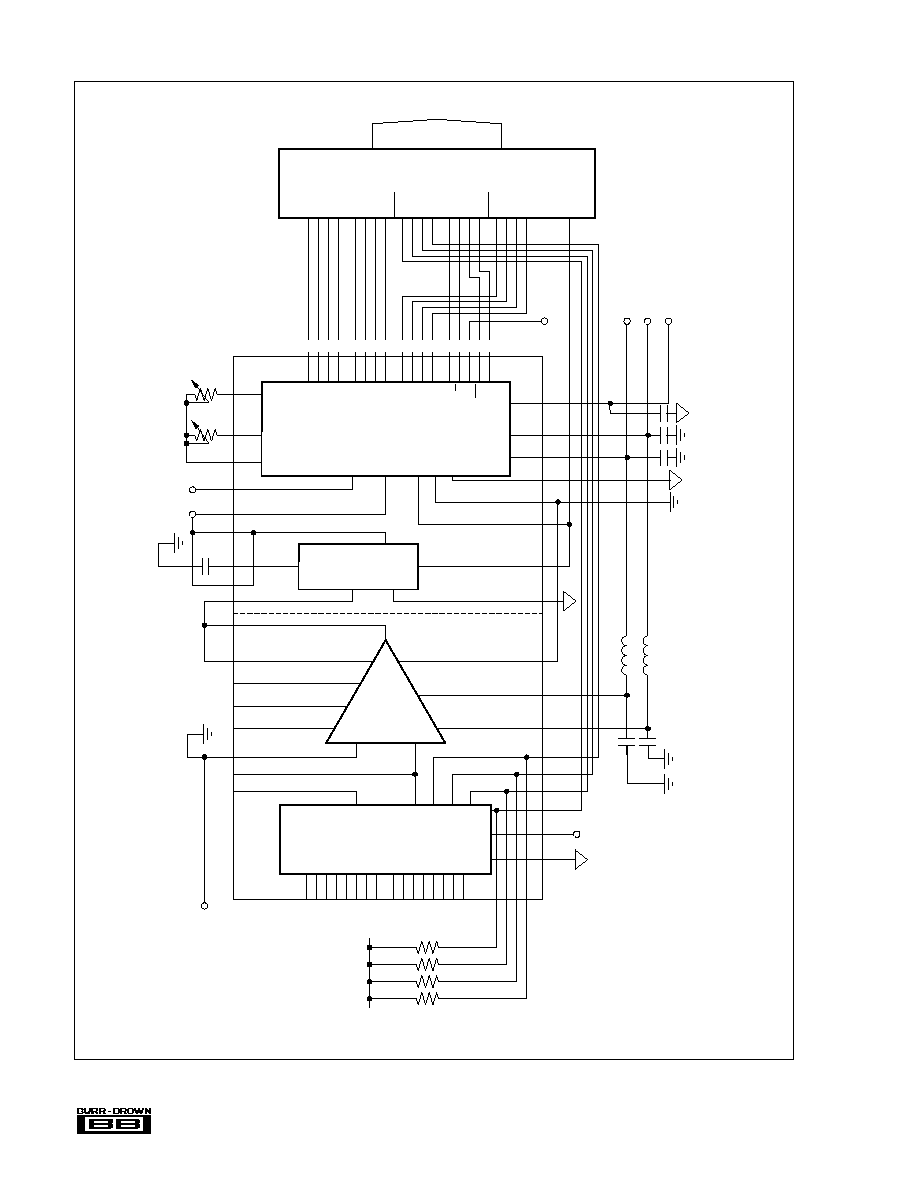
PIN CONFIGURATIONS
51
34 33 32 31 30 29 28 27 26 25 24 23 22 21 20 19 18
50
49
48
47
46
45
44
43
42
41
40
39
38
37
36
35
52 53 54 55 56 57 58 59 60 61 62 63 64 65 66 67 68
1
2
3
4
5
6
7
8
9
10
11
12
13
14
15
16
17
AMP OUT
AMP REF
+15V (1)
�15V (1)
+5V (2)
STATUS
D11
D10
D9
D8
D7
D6
D5
D4
D3
D2
D1
MUX ADD2
MUX ADD1
MUX ADD0
MUX ENABLE
CH0
CH1
CH2
CH3
CH4
CH5
CH6
CH7
S/H IN
NC
S/H OUT
HOLD CAP
S/H OUT
MUX ADD3
DCOM (1)
CH8
CH9
CH10
CH11
CH12
CH13
CH14
CH15
RG
G10
G100
MUX OUT +/AMP IN+
AMP IN�
NC
AMP SENSE
S/H COM (2)
S/H CONT
BYTE SELECT
CS
DATA MODE
R/C
CE
+15V (2)
REF OUT
ACOM (2)
REF IN
BIP OFF
ADC IN (10V)
ADC IN (20V)
�15V (2)
DCOM (2)
D0
MUX
INA
A/D
DOTTED
LINE
SHOWS
SUPPLY
SEPARATION
PIN
GROUPING
BY
FUNCTION
S/H
51
34 33 32 31 30 29 28 27 26 25 24 23 22 21 20 19 18
50
49
48
47
46
45
44
43
42
41
40
39
38
37
36
35
52 53 54 55 56 57 58 59 60 61 62 63 64 65 66 67 68
1
2
3
4
5
6
7
8
9
10
11
12
13
14
15
16
17
AMP OUT
AMP REF
+15V (1)
�15V (1)
+5V (2)
STATUS
D11
D10
D9
D8
D7
D6
D5
D4
D3
D2
D1
MUX ADD2
MUX ADD1
MUX ADD0
MUX ENABLE
CH0+
CH1+
CH2+
CH3+
CH4+
CH5+
CH6+
CH7+
S/H IN
NC
S/H OUT
HOLD CAP
S/H OUT
S/H COM (2)
S/H CONT
BYTE SELECT
CS
DATA MODE
R/C
CE
+15V (2)
REF OUT
ACOM (2)
REF IN
BIP OFF
ADC IN (10V)
ADC IN (20V)
�15V (2)
DCOM (2)
D0
MUX
INA
A/D
DOTTED
LINE
SHOWS
SUPPLY
SEPARATION
PIN
GROUPING
BY
FUNCTION
S/H
NC
DCOM (1)
CH0�
CH1�
CH2�
CH3�
CH4�
CH5�
CH6�
CH7�
RG
G10
G100
MUX OUT +/AMP IN+
AMP IN�
MUX OUT�
AMP SENSE
TOP VIEW
SDM863/SDM873
TOP VIEW
SDM862/SDM872

�
SDM862/863/872/873
7
PIN DESIGNATION
DEFINITION
COMMENTS
SDM8X2 = SDM862 OR SDM872
CH0 to CH15
Channel Inputs
Analog Inputs (Total 16) for single-ended and differential operation. Unused
CH0 to CH7 (+, �)
inputs must be connected to analog common.
(PINS 40 to 47, 54 to 61)
MUX OUT+/AMP IN+
MULTIPLEXER "HI" OUTPUT
On the SDM8X2 this is the multiplexer output. On the SDM8X3 it is the
output of the positive selected inputs. It is connected internally to the
(PIN 65)
positive input of the instrumentation amplifier.
MUXOUT (Pin 67)
MULTIPLEXER "LO" OUTPUT
This pin is used on the SDM8X3 only. It should be connected to the negative
input of the instrumentation amplifier.
AMP IN (Pin 66)
Negative input of instrumentation
On the SDM8X2 this should be connected to analog common. On the
amplifier
SDM8X3 it should be connected to Muxout--(Pin 67).
AMP OUT (Pin 1)
Output of instrumentation amplifier
This pin should be connected to the input of the S/H amplifier (Pin 39).
AMP SENSE (Pin 68)
Output sense line of instrumentation
This pin will normally be connected direct to AMP OUT (Pin 1).
amplifier
AMP REF (Pin 2)
Reference for amplifier output
This pin will normally be connected to analog common. Care should be
taken to minimize tracking and contact resistance to analog common to
optimize system accuracy.
S/H OUT (Pins 35/37)
Output of sample/hold amplifier
Two pins are provided to facilitate a guard ring around the hold capacitor
pin. These pins should be connected to either ADC in (20V) or ADC in (10V)
depending on the desired range.
HOLD CAP (Pin 36)
Connection for hold capacitor on
The tracking to the hold capacitor should be as short as possible and a
S/H amplifier
guard ring employed using Pins 35 and 37.
ADC IN (20V); ADC IN (10V)
Inputs to A/D converter
Connect to S/H amplifier output. Use appropriate pin for desired range.
(Pins 21, 22)
RG, G10, G100
Gain settling pins on instrumentation
For Gain = 1, no connections. For Gain = 10, connect G10 to RG.
(Pins 62, 63, 64)
amplifier
For Gain = 100, connect G100 to RG.
REF OUT (PIN 26)
10V Reference voltage
This is the reference voltage for the A/D converter.
REF IN, BIP OFF
Reference input and offset input to
Connect trim potentiometers (or select-on-test resistors) to these pins for
(Pins 24, 23)
A/D converter
unipolar or bipolar operation as shown in Figures 12, 13.
S/H IN (Pin 39)
Input to sample/hold amplifier
Connect to amp out (Pin 1).
MUX ENABLE (Pin 48)
Multiplex enable/disable
Logic `1' on this pin will enable a selected channel on the internal
multiplexer. Logic `0' de-selects all channels.
MUX ADD0 to MUX ADD3
Address inputs for channel selection
These address lines select a particular channel as specified in Figure 24.
(Pins 49 to 52)
S/H CONT (Pin 33)
Track/Hold control on S/H amplifier
Logic `1' holds an analog value for conversion by the A/D converter. This line
may be controlled by the status (Pin 6) of the converter to simplify external
timing control.
S/H COM (Pin 34)
Reference for S/H logic control
Connect to digital common.
D0 to D11 (Pins 7 to 18)
3-state digital outputs
The 12- or 8-bit result of a conversion is available as output on these pins
(D0-LSB, D11-MSB).
STATUS (Pin 6)
Status of A/D conversion
This output is at logic `1' while the internal A/D converter is carrying out a
conversion. This pin may be used to directly control the S/H amplifier.
CE (Pin 28)
Chip enable
This input must be at logic `1' to either initiate a conversion or read output
data (see Figures 10, 17, 18, 19, 20).
CS (Pin 31)
Chip select
This input must be at logic `0' to either initiate a conversion or read output
data (see Figures 10, 17, 18, 19, 20).
R/C (Pin 29)
Read/convert
Data can be read when this pin is logic `1' or a conversion can be initiated
when this pin is logic `0'. This pin is typically connected to the R/W control
line of a microprocessor-based system (see Figures 10, 17, 18, 19, 20).
DATA MODE (Pin 30)
Select 12- or 8-Bit Data
When data mode is at logic `1' all 12 output data bits are enabled
simultaneously. When data mode is at logic `0' MSBs and LSBs are
controlled by byte select (Pin 32).
BYTE SELECT (Pin 32)
Byte address, short cycle
When reading output data, byte select at logic `0' enables the 8 MSBs. Byte
select at logic `1' enables the 4 LSBs. The 4 LSBs can therefore be connected
to four of the MSB lines for inter-connection to an 8-bit bus. In start convert
mode, logic `0' enables a 12-bit conversion while logic `1' will short cycle the
conversion to 8 bits (see Figure 10).
+15V(1), +15V(2)(Pins 3, 27)
Power Supply
Connect to +15V supply using decoupling as indicated in Figures 15, 16.
�15V(1), �15V(2)(Pins 4, 20)
Power Supply
Connect to �15V supply using decoupling as indicated in Figures 15, 16.
ACOM(2) (Pin 25)
Analog Common
Analog common connection. Note that a common (including digital
common) should be connected together at one point close to the device.
DCOM (1) (Pin 53)
Reference for MUX logic control.
Connect to digital common.
+5V (Pin 5)
Logic power supply
Connect to +5V digital supply line with decoupling as in Figures 15, 16.
DCOM(2) (Pin 19)
Reference for A/D converter control
Connect to S/H common at one point close to device.
lines
NC (Pin 38)
No internal connection

�
SDM862/863/872/873
8
All data acquisition systems using a MUX require consider-
ation of the errors that may be introduced by MUX output
capacitance. The applications information explains this more
fully in the input filtering section.
Shown in Figure 3 is an application that demonstrates the
flexibility of signal conditioning and gives the opportunity
to use a higher bandwidth filter. Diodes shown are low
leakage types (1na). The low output impedance of the
amplifiers reduces the time taken to charge MUX capaci-
tance C
M
.
INSTRUMENT AMPLIFIER
The instrument amplifier (INA) presents a very high input
impedance to the signal source, eliminating gain errors
introduced by voltage divider action between the source
output impedance and SDM input impedance. Where the
differential models are used, the INA performs the differen-
tial to single-ended conversion required to drive the sample/
hold amplifier. Gains may be set by using external jumpers,
to values of 1 (no jumper), 10 and 100. For gains other than
these presets, the following formula may be used to find an
external resistor value to add in series with the G = 10 or G
= 100 jumpers.
40k
Where Ri = 4444
, G = 10 input.
G � 1
404
, G = 100 input.
It should be noted that the internal gain set resistors have a
�
20% tolerance and
�
20ppm/
�
C drift.
to ensure that neither of the differential inputs exceed the
maximum input range. Otherwise, signal distortion will
result. A return path for the input bias currents must always
be provided. This prevents the charging of stray capaci-
tances in applications using floating sources, such as trans-
formers and thermocouples. Multiplexer inputs are protected
from overvoltage, as indicated in the electrical specifica-
tions, and should be current limited to 20mA.
Where high-speed operation is required and channels require
rapid sampling, then it is important to buffer the inputs
against the effect of current sharing between the MUX
output capacitance and the input filter capacitance. See
Figure 2.
SYSTEM DESCRIPTION
The SDM comprises four circuit elements--an input-pro-
tected multiplexer, an instrumentation amplifier, a sample/
hold amplifier, and an analog-to-digital converter.
INSTALLATION
MULTIPLEXER
The SDM family has a choice of input multiplexers (MUX).
SDM862 and SDM872:
16 single-ended inputs
SDM863 and SDM873:
8 differential inputs
On all models, the analog inputs may be expanded using the
enable control. See Figure 1. When the enable is at a logic
"0," the internal MUX is disabled, allowing additional
multiplexers to be connected in parallel. The limiting factor
for the number of additional multiplexers is the cumulative
effect of leakage current flowing in the signal source imped-
ance, causing offset errors.
Differential inputs will generally eliminate the noise associ-
ated with common system grounds, but care must be taken
FIGURE 1. External Multiplexer Connections for Differen-
tial and Single-Ended Operation.
FIGURE 2. Filter and MUX Capacitance
.
� Ri
R
ext
=
C
f
C
M
C
f
MUX
A3
A2
A1
A0
Out
A3
A2
A1
A0
Out
A2
A1
A0
� Out
+Out
D-Com
EN
D-Com
EN
D-Com
EN
49 50 51 52 48 65
66
53
SDM8X2
66
A2
A1
A0
�Out
+Out
D-Com
EN
A0
A1
A2
A3
MUX
Extern
49 50 51 48
65
53
SDM8X3
67
A0
A1
A2
A3
INA
INA
A4
MUX
Intern
MUX
Intern
MUX
Extern

�
SDM862/863/872/873
9
Matching of R
1
and R
3
is required to maintain high
common-mode rejection (CMR), R
2
sets the gain and may
be varied without effect on CMR.
To ensure that the effects of temperature are minimized
when altering the gain with external components, it is very
important to use low tempco resistors. When connecting the
output sense, ensure that series resistance is minimized
because resistance present will degrade CMR.
FIGURE 5. Increasing Output Amplifier Gain.
20k
20k
4.44k
404
FET Input
10k
10k
10k
10k
FET Input
A1
A3
A2
R
1
R
2
R
3
FIGURE 4. Use External Gain Set Resistor.
�
+
�
+
+
�
+
�
C
f
+
�
R
f
MUX
C
M
�V
+V
C
f
C
f
R
f
C
f
R
f
C
f
10V
10V
R
f
R
i
R
f
R
f
FIGURE 3. Example Application Illustrating Flexible Signal
Conditioning.
Output
20k
20k
X10
X100
4.44k
404
FET Input
10k
10k
10k
10k
FET Input
+In
R
G
R
EXT
�In
A1
A3
A2
Sense
Ref
Where it is necessary to keep the input amplifiers from
saturating or increasing the overall gain, then the gain of the
output amplifier can be increased from unity by using the
circuit in Figure 5.
The values of the resistors in Figure 5 are in the following
table.
O/P GAIN
R
1
and R
3
R
2
2
1200
2740
5
1000
511
10
1500
340
FIGURE 6. Typical INA Settling Time and CMR.
10
100
1
1k
10k
100k
1M
120
100
80
60
40
20
0
Common-Mode Rejection (dB)
Frequency (Hz)
Gain (V/V)
Settling Time (�s)
1
10
100
10
5
0
CMR vs FREQUENCY
SETTLING TIME vs GAIN
(0.01%, 20V Step)
Gain = 1
Gain = 10
Gain = 100
�
SDM862/863/872/873
10
acquisition time and droop rate, as the hold capacitor is
increased in value it takes longer to charge, and hence there
is a corresponding increase in acquisition time and reduction
in droop rate. The droop rate is determined by the amount of
leakage present in the SDM, board leakage and the dielectric
absorption of the hold capacitance. The hold capacitor is
also a compensation element for the S/H and should not be
reduced below 2nf for good stability. The offset error in
sample mode is not affected by the hold capacitor. However,
during the transition to hold mode there is approximately
5pC of charge injected into the hold capacitor, causing an
offset error that has been nulled for use with a 5nf hold
capacitor. Any other value for the hold capacitor will cause
a minor but fixed hold mode offset to be introduced, and is
proportional to the change in value from 5nf. Therefore, the
SDM should be offset nulled with the S/H in hold mode.
ANALOG-TO-DIGITAL CONVERTER
This circuit element converts the analog voltage presented
by the sample/hold amplifier to a digital number in binary
format under control of the digital signals detailed in Figure
9. The converter can convert unipolar and bipolar signals in
the range 10V and 20V. It can be calibrated to remove gain
and offset errors from the entire system. The converter
contains its own clock, voltage reference, and microproces-
sor interface with 3-state outputs. The converter will nor-
mally be used to digitize signals to 12-bit resolution, but it
can be short-cycled to provide 8-bit resolution at higher
speed. The digital output is compatible with 8- or 16-bit data
buses, the data format being selected by control signals as
detailed in Figure 9.
SAMPLE/HOLD AMPLIFIER
The Sample/Hold amplifier (S/H) is used to track the incom-
ing signal and "hold" the required instantaneous value so
that it does not change while the ADC is carrying out its
conversion. Timing for the S/H may be derived from the
STATUS output of the ADC, with care being taken to
comply with the SDM timing considerations.
Capacitors with high insulation resistance and low dielectric
absorption such as TeflonTM, polystyrene or polypropylene
should be used as storage elements. (Polystyrene should not
be used above +80
�
C.) TeflonTM is recommended for high
temperature operation. Care should be taken in the printed
circuit layout to minimize stray capacitance and leakage
currents from the capacitor to minimize charge offset and
droop errors. The use of a guard ring driven by the S/H
output around the pin connecting to the hold capacitor is
recommended. (Refer to the application board layout for an
example of this.)
The value of the external hold capacitor determines the
droop rate, charge offset and acquisition time of the S/H,
Figure 8. Droop rate for the SDM is specified with a hold
capacitor value of 4700pf. There is a trade-off between
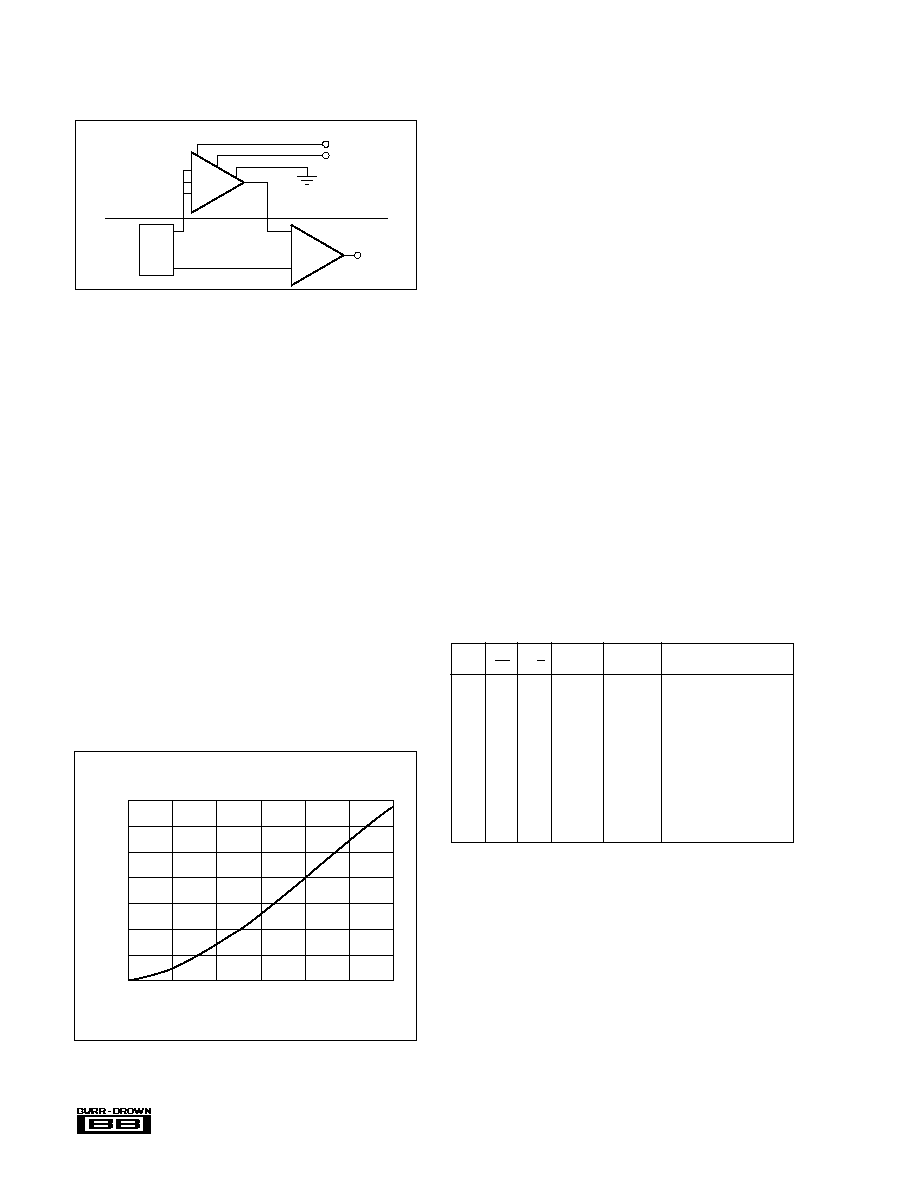
FIGURE 7. Setting Programmable Gains.
Some applications may require programmable gains. This
may be realized with Figure 7.
1
2
3
15
66
6
7
8
67
SDM8X3
MUX
INA
Gain Sel
TTL/CMOS
1-10-100
PGA
102
FIGURE 8. Acquisition Time vs Hold Capacitance for a 10V
Step Settling to
�
10mV of Final Value.
DATA
BYTE
CE
CS
R/C
MODE
SELECT
OPERATION
0
X
X
X
X
None
X
1
X
X
X
None
0
0
X
0
Initiate 12-bit conversion
0
0
X
1
Initiate 8-bit conversion
1
0
X
0
Initiate 12-bit conversion
1
0
X
1
Initiate 8-bit conversion
1
0
X
0
Initiate 12-bit conversion
1
0
X
1
Initiate 8-bit conversion
1
0
1
1
X
Enable 12-bit output
1
0
1
0
0
Enable 8 MSBs only
1
0
1
0
1
Enable 4 LSBs plus 4
trailing zeros
FIGURE 9. Control Input Truth Table.
LINEARITY ERROR
Linearity error is defined as the deviation of actual code
transition values from the ideal transition values. Ideal
transition values lie on a line drawn through zero (or minus
full scale for bipolar operation) and plus full scale. The zero
value is located at an analog input value 1/2LSB before the
first code transition (000
H
to 001
H
). The full-scale value is
located at an analog value 3/2LSB beyond the last code
transition (FFE
H
to FFF
H
) (see Figure). Thus, with the SDM
connected for bipolar operation and with a full-scale range
(or span) of 20V (
�
10V), the zero value of �10V is 2.44mV
6
10
9
8
7
6
5
4
3
8
4
10
12
14
16
Acquisition Time (�s)
Hold Capacitance (nF)
ACQUISITION TIME vs HOLD CAPACITANCE
For a 10V Step to �10mV of Final Value

�
SDM862/863/872/873
11
below the first code transition (000
H
to 001
H
at �9.99756V)
and the plus full-scale value of +10V is 7.32mV above the
last code transition (FFE
H
to FFF
H
at +9.99268) (see Figure
13).
NO MISSING CODES
(DIFFERENTIAL LINEARITY ERROR)
A specification which guarantees no missing codes requires
that every code combination appear in a monotonically-
increasing sequence as the analog input is increased through-
out the range. Thus, every input code width (quantum) must
have a finite width. If an input quantum has a value of zero
(a differential linearity error of �1LSB), a missing code will
occur.
The SDM is guaranteed to have no missing codes to 12-bit
resolution over it's respective specification temperature
ranges.
UNIPOLAR OFFSET ERROR
An SDM connected for unipolar operation has an analog
input range of 0V to plus full scale. The first output code
transition should occur at an analog input value 1/2LSB
above 0V. Unipolar offset error is defined as the deviation of
the actual transition value from the ideal value. The unipolar
offset temperature coefficient specifies the change of this
transition value versus a change in ambient temperature.
BIPOLAR OFFSET ERROR
A/D converter specifications have historically defined bipo-
lar offset as the first transition value above the minus full-
scale value. The SDM specification, however, follows the
terminology defined for the 574 converter several years ago.
Thus, bipolar offset is located near the midscale value of 0V
(bipolar zero) at the output code transition 7FFH to 800H.
Bipolar offset error for the SDM is defined as the deviation
of the actual transition value from the ideal transition value
located 1/2LSB below 0V. The bipolar offset temperature
coefficient specifies the maximum change of the code tran-
sition value versus a change in ambient temperature.
FULL SCALE CALIBRATION ERROR
The last output code transition (FFE
H
to FFF
H
) occurs for an
analog input value 3/2LSB below the nominal full-scale
value. The full-scale calibration error is the deviation of the
actual analog value at the last transition point from the ideal
value. The full-scale calibration temperature coefficient speci-
fies the maximum change of the code transition value versus
a change in ambient temperature.
OPERATING INSTRUCTIONS
OPERATING MODES
The SDM can operate in one of two modes, namely serial
and overlap, as shown in Figure 10. In serial mode, control
of the device is such that a multiplexer channel X is first
selected, time is then allowed for the instrumentation ampli-
fier to settle, the sample/hold amplifier is set to HOLD mode
and finally a conversion is carried out. This procedure is
then repeated for channel Y. Faster throughput can be
obtained using overlap mode. While a conversion is being
Conversion
Signal Acquisition
SERIAL MODE
Time
Signal Acquisition
Signal Acquisition
Conversion
Time
MUX
Selection
(X)
Instrumentation
Amp
Settling
Sample/
Hold
Acquisition
A/D
Conversion
Data
Valid
MUX
Selection
(Y)
MUX
Selection
(X)
Instrumentation
Amp
Settling
Sample/
Hold
Acquisition
MUX
Selection
(Y)
Instrumentation
Amp
Settling
Sample/
Hold
Acquisition
MUX
Selection
(Z)
A/D
Conversion on
Channel (X)
Data Valid
A/D
Conversion on
Channel (Y)
OVERLAP MODE
FIGURE 10. Serial and Overlap Modes of Operation.

�
SDM862/863/872/873
12
carried out by the ADC on a voltage from channel X held on
the sample/hold, channel Y is selected and the multiplexer
and instrumentation amplifier allowed to settle. In this way,
the total throughput time is limited only by the sum of the
sample/hold acquisition time and the ADC conversion time.
CALIBRATION � UNIPOLAR
If adjustment of unipolar offset and gain are not required,
then the gain set potentiometer in Figure 11 (Unipolar
operation) may be replaced with a 50
, 1% metal film
resistor, and the offset network replaced with a connection
from pin 23 to ground.
FIGURE 11. Unipolar Calibration.
CALIBRATION - BIPOLAR
If adjustment of bipolar offset and gain are not required then
the gain set and offset potentiometers in Figure 12 (Bipolar
operation) may both be replaced with 50
, 1% metal film
resistors.
FIGURE 12. Bipolar Calibration.
21
22
23
24
26
20V
Span
10V
Span
Inputs
SDM
(Gain)
100
(Offset)
100
CALIBRATION - GENERAL
The input voltage ranges of the ADC are 0-10V,
�
5V and
�
10V. Calibration in all ranges is achieved by adjusting the
offset and gain potentiometers (indicated in Figures 11 and
12) such that the 000 to 001 code transition takes place at
+1/2LSB from full-scale negative (�FS) and the FFE to FFF
transition takes place at �3/2LSB from full-scale positive
(+FS). The procedure is therefore to select the required range
from Figure 13, apply the specified (�FS+1/2LSB) voltage
to any selected input channel and adjust the offset potenti-
ometer for the 000 to 001 transition. The (+FS�3/2LSB)
voltage should then be applied to the same channel and the
gain potentiometer adjusted for the FFE to FFF transition.
The offset should always be made before the gain adjustment.
FULL-SCALE
000 TO 001
FFE TO FFF
1LSB
RANGE
TRANSITION VOLT.
TRANSITION VOLT.
EQUALS
0�10V
+0.0012V
+9.9963V
2.44mV
�
5V
�4.9988V
+4.9963V
2.44mV
�
10V
�9.9976V
+9.9927V
4.88mV
FIGURE 13. Code Transition Ranges.
Full-Scale
Calibration
Error
Rotates
The
Line
Offset
Error
Shifts
The Line
(Bipolar
Offset
Transaction)
Midscale
(Bipolar
Zero)
FFF
H
FFE
H
FFD
H
802
H
801
H
800
H
7FF
H
7FE
H
001
H
000
H
002
H
Digital Output
1/2LSB
Zero
(�Full Scale)
Zero
(�Full-Scale
Calibration
Transition)
1/2LSB
3/2LSB
+Full-Scale
Calibration
Transition
+Full
Scale
Analog Input
FIGURE 14. SDM Transfer Characteristic Terminology.
GROUNDING, DECOUPLING
AND LAYOUT CONSIDERATIONS
It should be noted that the multiplexer/instrumentation am-
plifier section and sample/hold plus ADC section of the
SDM have separate power connections. This is to enable
more flexible grounding techniques to be implemented,
Figures 15, 16. It also facilitates the use of independent
decoupling of the analog front-end power supply, and the
ADC plus associated digital circuitry power supply if de-
sired. In this way, a separately decoupled analog front-end
can be made to be substantially more immune to power
supply noise generated by the ADC circuitry than if the
20V
Span
10V
Span
Inputs
(Gain)
SDM
+15V
�15V
21
22
23
24
26
160
100
100k
(Offset)
100k

�
SDM862/863/872/873
13
power supplies to the two sections were directly connected.
This feature is important where low-level signals are in use
or high input signal noise immunity is desired.
The output section has three grounds:
Pin 25 Analog Common, A/D Converter
Pin 34 S/H Amp Digital Input Reference
Pin 19 Digital Common, A/D Converter
The input section has one ground:
Pin 53 Common for digital MUX-inputs and power
supply decoupling.
All grounds have to be interconnected externally to the
SDM, and it is recommended that all grounds are connected
via one track to a single point as close as possible to the
SDM. To check that the grounding structure is correct, the
ground tracking should be sketched and a grounding "tree"
should result whereby all grounds route to a central point.
In general, layout should be such that analog and digital
tracks are separated as much as possible with coupling
between analog and digital lines minimized by careful lay-
out. For instance, if the lines must cross they should do so
at right angles to each other. Parallel analog and digital lines
should be separated from each other by a pattern connected
to common.
Signal-Ref (Single-Ended)
DCOM (1)
�V
+V
Output-Ref
SHC GND
ACOM (2)
DCOM (2)
+15V
�15V
+5V
66
53
4
3
2
34
25
19
27
20
5
100�H
100�H
+5V
�15V
+15V
Signal-Ref
NOTE: (1) 10�F tantalum in parallel with 100nF ceramic.
(1)
(1)
(1)
(1)
(1)
FIGURE 15. Recommended Decoupling of Power Supplies.
�V
0
+V
0
+5V
�V
0
+V
4
53
3
20
27
25
19
5
5V
+5V
1/2 SDM
ISO100
4 Opto-Couplers
MUX-Address
MUX-Address
+5V
INA
1/2 SDM
PWR305
1
2
39
100�H
100�H
100�H
100�H
100�H
FIGURE 16. Galvanic Isolation Between Analog and Digital Signals.
�
SDM862/863/872/873
14
FIGURE 17. The SDM Connected to an Input/Output Port.
RG
�In
G10
G100
Sense
INA
Out
+In
Ref
V
EE
V
CC
Analog-Ref
67
65
66
62
63
64
68
1
39
35
36
44.7nF
37
21
22
26
24
23
B0
B1
B2
B3
B4
B5
B6
B7
C0
C1
C2
C3
C4
C5
C6
C7
A0
A1
A2
A3
A4
A5
A6
A7
47
46
45
44
43
42
41
40
54
55
56
57
58
59
60
61
CH0
1
2
3
4
5
6
7
8(0)
9(1)
10(2)
11(3)
12(4)
13(5)
14(6)
15(7)
MUX
(Out)
Out
A3
A2
A1
A0
DCOM
EN
53
48
49
50
51
52
4
3
2
+5V
34
33
6
25
19
27
20
5
+5V
(12 Bit)
+15V
�15V
+5V
Ref
Out
Ref
In
Bip
Off
ADC
In(10V)
In(20V)
Status
AGND
DGND
LSB D0
D1
D2
D3
D4
D5
D6
D7
D8
D9
D10
MSB D11
CE
R/C
Data M.
CS
Byte S.
Hold
Cap
In
Out
SHC
Gnd
Cont
8255 Port
R
100
+15V
�15V
+5V
S/H
R
100
+5V
1k
17
18
32
31
30
29
28
7
8
9
10
11
12
13
14
15
16

�
SDM862/863/872/873
15
D0
D1
D2
D3
D4
Hold
Cap
In
Out
SHC
Gnd
Cont
Ref
Out
Ref
In
Bip
Off
D0
D1
D2
D3
D4
D5
D6
D7
D8
D9
D10
MSB D11
CE
R/C
Data M.
CS
Byte S.
+15V
�5V
+5V
In (10V
In (20V)
D0
D1
D2
D3
D4
D5
D6
D7
D8
D9
D10
D11
D0
D1
D2
D3
D4
D5
D6
D7
A0
A1
A2
A3
+15V (12 Bit)
34
33
6
25
19
27
20
5
37
21
22
26
24
23
36
35
39
Status
AGND
DGND
.47nF
R
50
74244
74244
1G
2G
1G
2G
G
OC
D
Q
18
17
16
15
14
13
12
11
10
9
8
7
28
29
30
31
32
D15
CS
RD
WR
CS
74373
MUX
Bip
Off
D0
D1
D2
D3
D4
D5
D6
D7
D8
D9
D10
MSB D11
CE
R/C
Data M.
CS
Byte S.
+5V
D0
D1
D2
D3
D4
D5
D6
D7
D8
D9
D10
D11
A0
A1
A2
A3
+15V (12 Bit)
5
23
74244
74244
1G
2G
1G
2G
G
OC
D
Q
18
17
16
15
14
13
12
11
10
9
8
7
D15
CS
RD
WR
CS
74373
MUX
WR
CS
Status
S/H Cont
Fully Controlled Mode
Stand Alone Mode
ADC
S/H
R
50
28
29
30
31
32
FIGURE 18. The SDM Connected to a 16-Bit-BUS.

�
SDM862/863/872/873
16
FIGURE 19b. 68000/SDM Interface.
FIGURE 19a. SDM on the Z80 Interface.
R
100
4.7nF
R
100
Address
Decode
Z80
ADC
S/H
34
19
25
6
27
20
5
In
Hold
Cap
Out
SHC
Gnd
Cont
Ref
Out
Ref
In
Bip
Off
D0
D1
D2
D3
D4
D5
D6
D7
D8
D9
D10
MSB D11
CE
R/C
DATAM.
CS
Bytes
+5V
�15V
+15V
DGND
AGND
Status
In (20V)
In (10V)
D0
D1
D2
D3
A0
A1
A2
A3
74LS175
Reset
A1 � A7
AO
RD
WR
D7
D6
D5
D4
D3
D2
D1
D0
39
35
36
37
21
22
26
24
23
33
18
17
16
15
14
13
12
11
10
9
8
7
28
29
30
31
32
IORQ
MUX
4.7nF
R
100
ADC
S/H
34
19
25
6
27
20
5
In
Hold
Cap
Out
SHC
Gnd
Cont
Ref
Out
Ref
In
Bip
Off
D0
D1
D2
D3
D4
D5
D6
D7
D8
D9
D10
MSB D11
CE
R/C
DATAM
CS
Bytes
+5V
�15V
+15V
DGND
AGND
Status
In (20V)
In (10V)
39
35
36
37
21
22
26
24
23
33
18
17
16
15
14
13
12
11
10
9
8
7
28
29
30
31
32
Data Bus
LS
374
SDM
Status
Pin 6
SDM
Status
Address
Bus
Address
Decode
68000
R/W
UDS
DTACK
LOS
+5V
LS
374
R
100

�
SDM862/863/872/873
17
FIGURE 19c. IBM PC SDM Interface.
R
100
4.7nF
R
100
Adress
Decode
IBM PC or XT
Card Slot
ADC
S/H
34
19
25
6
27
20
5
In
Hold
Cap
Out
SHC
Gnd
Cont
Ref
Out
Ref
In
Bip
Off
D0
D1
D2
D3
D4
D5
D6
D7
D8
D9
D10
MSB D11
CE
R/C
DATAM
CS
Bytes
+5V
�15V
+15V
DGND
AGND
Status
In (20V)
In (10V)
D0
D1
D2
D3
A0
A1
A2
A3
Reset
A1 - A9
AO
IOR
IOW
D7
D6
D5
D4
D3
D2
D1
D0
39
35
36
37
21
22
26
24
23
33
18
17
16
15
14
13
12
11
10
9
8
7
28
29
30
31
32
MUX
AEN
FIGURE 20. SDM on the 6502 BUS.
4.7nF
R
100
ADC
S/H
34
19
25
6
27
20
5
In
Out
SHC
GND
Cont
Ref
Out
Ref
In
Bip
Off
D0
D1
D2
D3
D4
D5
D6
D7
D8
D9
D10
MSB D11
CE
R/C
DATAM
CS
Bytes
+5V
�15V
+15V
DGND
AGND
Status
In (20V)
In (10V)
39
35
36
37
21
22
26
24
23
33
18
17
16
15
14
13
12
11
10
9
8
7
28
29
30
31
32
D0
D1
D2
D3
A0
A1
A2
A3
74LS 175
Reset
A4
Select
8 Bit
D0
D1
D2
D3
D4
D5
D6
�2
D7
R/W
A0
BUS
Hold
Cap
R
100

�
SDM862/863/872/873
18
CONTROLLING THE SDM
The Burr-Brown SDM family can be easily interfaced to
most microprocessor systems, as shown in Figures 17-20.
The microprocessor may control each conversion, or the
converter may operate in a stand-alone mode controlled only
by the R/C input.
STAND-ALONE OPERATION
The stand-alone mode is used in systems containing dedi-
cated input ports which do not require full bus interface
capability.
Control of the converter is accomplished by a single control
line connected to R/C. In this mode CS and BYTE SELECT
are connected to LOW and CE and DATA MODE are
connected to HIGH. The output data are presented as 12-bit
words.
Conversion is initiated by a High-to-Low transition of R/C.
The three-state data output buffers are enabled when R/C is
high and STATUS is low. Thus, there are two possible
modes of operation; conversion can be initiated with either
positive or negative pulses. In each case the R/C pulse must
remain low for a minimum of 50ns.
Figure 21 illustrates timing when conversion is initiated by
an R/C pulse which goes low and returns to the high state
during the conversion. In this case, the three-state outputs go
to the high-impedance state in response to the falling edge of
R/C and are enabled for external access of the data after
completion of the conversion. Figure 22 illustrates the tim-
ing when conversion is initiated by a positive R/C pulse. In
this mode the output data from the previous conversion is
enabled during the positive portion of R/C. A new conver-
sion is started on the falling edge of R/C, and the three-state
outputs return to the high impedance state until the next
occurrence of a high R/C pulse. Table I lists timing specifi-
cations for stand-alone operation.
FULLY CONTROLLED OPERATION
Conversion Length
Conversion length (8-bit or 12-bit) is determined by the state
of the BYTE SELECT input, which is latched upon receipt
of a conversion start transition. BYTE SELECT is latched
because it is also involved in enabling the output buffers. No
other control inputs are latched. If BYTE SELECT is latched
high, the conversion continues for 8 bits. The full 12-bit
conversion will occur if BYTE SELECT is low. If all 12 bits
are read following an 8-bit conversion, the 3LSBs (DB0-
DB2) will be low (logic 0) and DB3 will be high (logic 1).
Word 1
Word 2
Processor
DB7
DB6
DB5
DB4
DB3
DB2
DB1
DB0
DB7
DB6
DB5
DB4
DB3
DB2
DB1
DB0
SDM
DB11
DB10
DB9
DB8
DB7
DB6
DB5
DB4
DB3
DB2
DB1
DB0
0
0
0
0
FIGURE 23. 12-Bit Data Format for 8-Bit Systems (connected as Figures 18 and 19).
Conversion Start
A conversion is initiated by a transition on any of three logic
inputs (CE, CS, and R/C)--refer to Figure 9. The last of the
three to reach the required state start the conversion and thus
all three may be dynamically controlled. If necessary, they
may change state simultaneously, and the nominal delay
time is independent of which input actually starts the con-
version. If it is desired that a particular input establish the
actual start of conversion, the other two should be stable a
minimum of 50ns prior to the transition of that input. Timing
relationships for start of conversion timing are illustrated in
Conversion Cycle Timing of the Digital Specifications.
SYMBOL
PARAMETER
MIN
TYP
MAX UNITS
t
HRL
Low R/C Pulse Width
50
ns
t
DS
STS Delay from R/C
200
ns
t
HDR
Data Valid After R/C Low
25
ns
t
HS
86X
STS Delay After Data Valid
300
500
1000
ns
t
HS
87X
100
300
600
ns
t
HRH
High R/C Pulse Width
150
ns
t
DDR
Data Access Time
150
ns
FIGURE 22. R/C Pulse High--Outputs Enabled Only Where
R/C is High.
R/C
Status
DB11�
DB0
Data Valid
High-Z State
t
HRH
t
DS
t
DDR
t
C
t
HDR
High-Z
FIGURE 21. R/C Pulse Low--Outputs Enabled After Con-
version.
R/C
Status
DB11�DB0
Data Valid
Data Valid
High-Z State
t
HRL
t
DS
t
HDR
t
HS
t
C
TABLE I. Stand-Alone Mode Timing.
�
SDM862/863/872/873
19
The STATUS output indicates the state of the converter by
being high only during a conversion. During this time the
three-state output buffers remain in a high-impedance state,
and therefore, data is not valid. During this period additional
transitions of the three control inputs will be ignored, so that
conversion cannot be prematurely terminated or restarted.
However, if BYTE SELECT changes state after the begin-
ning of conversion, any additional start conversion transition
will latch the new state of BYTE SELECT, possibly result-
ing in an incorrect conversion length (8 bit versus 12 bits)
for that conversion.
READING OUTPUT DATA
After conversion is initiated, the output data buffers remain
in a high-impedance state until the following four conditions
are met: R/C high, STATUS low, CE high, and CS low. In
this condition the data lines are enabled according to the
state of the inputs DATA MODE and BYTE SELECT. See
Read Cycle Timing for timing relationships and specifica-
tion.
In most applications the DATA MODE input will be
hardwired in either the high or low condition, although it is
fully TTL- and CMOS-compatible and may be actively
driven if desired. When DATA MODE is high, all 12
outputs lines (DB0-DB11 ) are enabled simultaneously for
full data word transfer to a 12-bit or 16-bit bus and the state
of the BYTE SELECT is ignored.
When DATA MODE is low, the data is presented in the
form of two 8-bit bytes, with selection of each byte by the
state of BYTE SELECT during the read cycle.
The BYTE SELECT input is usually driven by the least
significant bit of the address bus, allowing storage of the
output data word in two consecutive memory locations.
When BYTE SELECT is low, the byte addressed contains
the 8MSBs. When BYTE SELECT is high, the byte ad-
dressed contains the 4LSBs from the conversion followed by
four zeros that have been forced by the control logic. The
left-justified formats of the two 8-bit bytes are shown in
Figure 23. The design of the SDM guarantees that the BYTE
SELECT input may be toggled at any time without damage
to the output buffers occurring.
In the majority of applications, the read operation will be
attempted only after the conversion is complete and the
status output has gone low. In those situations requiring the
fastest possible access to the data, the read may be started as
much as (t
DD
max + t
HS
max) before STATUS goes low.
Refer to Read Cycle Timing for these timing relationships.
APPLICATIONS INFORMATION
ASSEMBLY OF SURFACE MOUNT PACKAGES
There are several assembly methods for the LCC versions of
the SDM8XX. The associated advantages and disadvantages
of three methods are outlined below.
1. DIRECT SURFACE MOUNT ONTO PCB
ADVANTAGES
DISADVANTAGES
Ease of assembly
Difficult to inspect solder joints
Low cost
Difficult to clean
Low weight
Choice of board material important in
Small footprint size
wide temperature range applications
In wide temperature applications it is important to match the
coefficients of thermal expansion of the board and the
SDM8XXL. Below is a list of materials and their approxi-
mate coefficients of linear thermal expansion.
MATERIAL
(ppm/
�
C)
Alumina (96%) - SDM Package
6-7
Copper-clad-Invar (50% Cu)
9
(30% Cu)
6
(10% Cu)
3
Epoxy-Kevlar (60% Kevlar)
6
Polyimide-Kevlar (40% Kevlar)
6
Beryllia
5
Polyimide-glass (x-axis)
12
(y-axis)
14
KevlarTM E.I. du Pont de Nemours & Co.
2. ATTACHMENT OF
SURFACE MOUNT EDGE CLIPS
ADVANTAGES
DISADVANTAGES
Ease of Inspection
Extra cost
Easy cleaning
Extra assembly
Thermal expansion taken up by
the flexing of the edge clips
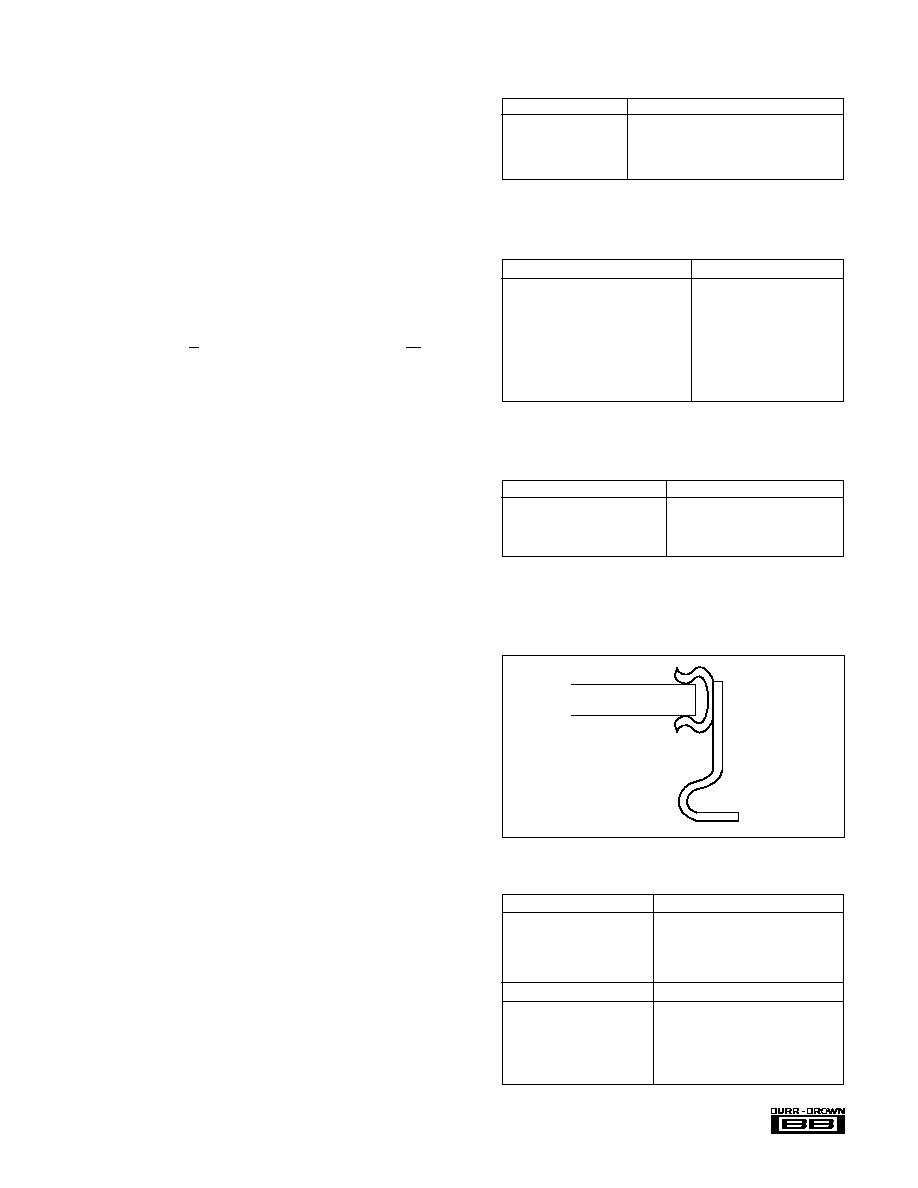
ASSEMBLY
The edge clips are attached to the edges of the SDM8XXL
as in Figure 24 before the device is mounted on to the board.
FIGURE 24. Edge Clip Assembly.
SDM
EDGE
CLIP
SUPPLIERS OF EDGE CLIPS
USA
USA
DIE-TECH INC.,
NAS Electronics,
R.D. 1, Sipe Road,
381 Park St.,
York Haven,
Hackensack,
PA 17370 USA
NJ 07602 USA
PHONE: (717) 938-6771
PHONE: (201) 343-3156
EUROPE
EUROPE
SEMI-DICE (UK) Ltd,
NASBRIT Ltd,
Buckingham House,
Wester Goudi Ind. Est.
Mineral Lane,
Dundee DD2 4UX
Chesham,
UK
Bucks. HP5 2AU UK
PHONE: 0382 622222
PHONE: 0494 771275

�
SDM862/863/872/873
20
3. SURFACE MOUNT SOCKET
ADVANTAGES
DISADVANTAGES
Board thermal expansion
Cost
not so critical
Extra height (if critical)
Ease of component
replacement
Below is the name and address of a supplier of a 68-pin surface mountable
socket.
The part number is:
Socket
212-068-012
Spring cover
CCS-004
USA
EUROPE
Methode Electronics INC,
Lucas Methode Connectors Ltd,
Interconnect Products Div.
Halifax Road
1700 Hick Road,
Ingrow Bridge,
Rolling Meadows, TX 75050
Keighley, Yorkshire BD21 5HR
USA
UK
PHONE: (312) 392-3500
PHONE: 0535 603282
General Comments
The advantages and disadvantages of all the methods men-
tioned above are for general use of surface mount compo-
nents. Every user will find that the importance of these
factors will depend on his application and situation.
EVALUATION BOARD
For the engineer who wishes to evaluate the SDM family,
Burr-Brown has designed printed circuit boards on a single
`Eurocard' (shown here for LCC only). These boards enable
the design engineer to experiment with various accuracy
improvement techniques which are described below. Special
consideration has been given to the grounding and circuit
layout techniques required when dealing with 12-bit analog
signals.
The printed circuit board has been designed so that the
solutions to several of the problems likely to be encountered
by the user can be examined.
It should not be thought that every user is required to adopt
all of the techniques used on the circuit board. In many
applications very few external components will be required.
However, in following the application guidelines illustrated
by the circuitry and accompanying notes, the designer will
be able to select and adapt the solutions most suited to their
won particular application or problem area.
Provisions for the following are made on the LCC PC board:
--68 pin LCC socket (Burr-Brown Part No. MC0068).
--8 differential or 16 single-ended inputs.
--Input filtering with overvoltage protection for each chan-
nel.
--Socket for quad D-type flip-flop 74175 (MUX address
latches).
--7 additional I.C. sockets for easy interfacing to various
BUS systems (connection by wire wrap techniques).
--2 voltage regulators (15V).
--LC power supply decoupling.
The layout pays particular attention to the requirements
when operating with precision analog signals. This requires
strict separation of the analog and digital areas. Analog and
digital commons are totally separated and connected to-
gether only at the commons of the supply voltage. All
common lines are low resistance and low inductance.
SUPPLY VOLTAGES
In order to avoid coupling between the external supply
voltage 15V supplies, 2 voltage regulators (78M15, 79L15)
are provided on the PC board. The unregulated supply
voltage may vary from
�
17V to
�
25V.
The MUX/INA section and SHC/ADC section of the SDM
have separate supply lines which can be inductively
decoupled. This is recommended in order to suppress the
high frequency noise which comes from the ADC during
conversion.
The power supply rejection of the instrumentation amplifier
reduces with increasing frequency. If high frequency noise
on the supplies is not decoupled it will be injected into the
signal path and cause errors. This effect can be particularly
pronounced when using the `overlap' mode since the instru-
FIGURE 25. Channel Select Truth Table.
SDM862/872
SDM863/873
Channel
MUX
MUX
MUX
MUX
MUX
Channel
MUX
MUX
MUX
MUX
Pair
ADD3
ADD2
ADD1
ADD0
Enable
Selected
ADD2
ADD1
ADD0
Enable
Selected
X
X
X
X
L
NONE
X
X
X
L
NONE
L
L
L
L
H
0
L
L
L
H
0
L
L
L
H
H
1
L
L
H
H
1
L
L
H
L
H
2
L
H
L
H
2
L
L
H
H
H
3
L
H
H
H
3
L
H
L
L
H
4
H
L
L
H
4
L
H
L
H
H
5
H
L
H
H
5
L
H
H
L
H
6
H
H
L
H
6
L
H
H
H
H
7
H
H
H
H
7
H
L
L
L
H
8
�
H
L
L
H
H
9
�
H
L
H
L
H
10
�
H
L
H
H
H
11
�
H
H
L
L
H
12
�
H
H
L
H
H
13
�
H
H
H
L
H
14
�
H
H
H
H
H
15
�

�
SDM862/863/872/873
21
mentation amplifier is settling to a new analog value while
the ADC is still carrying out the previous conversion.
The digital supply voltage is +5V and is also LC-filtered.
All supply lines are bypassed with a 10
�
F tantalum and a
100nF ceramic capacitor situated as close as possible to the
package.
If the voltage regulators for the
�
15V are not used, small
inductors for decoupling of the supply voltages are recom-
mended. If inductors are not fitted a dynamic ground loop
will be created from supply lines via bypass capacitors to
analog common.
INPUT PROTECTION
The multiplexer is protected up to an input voltage which
can exceed the supply voltage by a maximum of 20V. This
means, that with
�
15V supply voltage, the input voltage can
be
�
35V without damage. This is also the case when the
supply voltages are switched off (0V). The maximum input
voltage can then be
�
20V. For higher overvoltage protection
a series resistor has to be used. The current via the multi-
plexer should be limited to 20mA absolute maximum, 1mA
is preferred. For example, a 10k
series resistor would give
an additional 10V overprotection.
For much higher overvoltages (e.g. 100V), high value series
resistors cannot be used as offset errors would result. In
practice, a combination of series resistors and diodes is used.
The diodes are connected to
�
15V and will conduct when-
ever the input voltage exceeds the
�
15V supply voltage. The
diodes are selected by signal source impedance, as well as
filter resistance, as the diode leakage current across the
series resistor can cause offset and linearity errors. In this
circuit, IN4148 together with 10k
are used.
INPUT FILTER
Processor noise can be induced in the analog ground. Input
filtering is therefore recommended for analog data acquisi-
tion. Such high frequency noise signals can cause dynamic
overload of the instrumentation amplifier resulting in non-
linear behavior. This leads directly to digitizing errors.
The design of the filter takes into account the characteristics
of the SDM and of the signal source.
The following points have to be considered:
--The stray capacitance, output capacitance of the multi-
plexer and input capacitance of the instrument amplifier
(up to 80pf in some cases) has to be discharged in order
to minimize errors caused by `charge sharing.'
--The series resistor limits the current in the protection
diodes, but it also has to be selected for the required filter
time constant.
--The noise rejection of the filter has to be >80db in order
to satisfy a 12-bit A/D conversion.
As well as considering the above, different calculations
have to be carried out for single and differential input
signals.
Single-Ended Measurement
R
f
limits the maximum input current through the protection
diodes. In this case, R
f
has been chosen as 10k
and
together with the capacitor C
g
, forms the input filter time
constant (C
g
= 0.47
�
F). The time constant must be chosen
according to the requirements of the input signal bandwidth
and noise rejection. The multiplexer capacitance (C
m
) is
discharged mainly by C
g
. This means C
g
has to be suffi-
ciently large compared with C
m
or charged via R
f
prior to re-
sampling of the signal.
FIGURE 26.
INA
Analog In
R
f
Mux
C
m
C
g
FIGURE 27.
INA
C
g
Mux
C
m
C
f
R
f
R
f
Analog In
Analog In
C
g
Differential Measurement
Capacitor C
f
, is used for limiting the input signal frequency.
The bandwidth is calculated as follows:
When selecting the value of C
f
, it should be noted that C
m
has to be discharged when switching the multiplexer chan-
nels. This means that the voltage error of C
f
(induced by
`charge sharing' with C
m
) has to be smaller than 1LSB.
Therefore, C
f
should have a minimum value of a 0.47
�
F.
The resistors R
f
, together with the source impedance, have to
be sufficiently small in order to recharge C
f
prior to signal
sampling. This prevents errors in the signal value caused by
the charge stored on C
m
by the previously selected channel.
The 2 capacitors C
g
form together with R
f
a common-mode
filter. This filter greatly improves accuracy in a noisy envi-
ronment (decrease of common-mode rejection of instrumen-
tation amplifier with increasing frequency).
For good common-mode filter operation, both time con-
stants R
f
and C
g
should match each other within 2%. Addi-
tional errors will be induced by a mismatch.
Selected values are: C
f
= 0.47
�
F, C
g
= 10nF, R
f
= 10k
. The
filter reduces the signal slew rate so that the instrumentation
amplifier can follow the voltage variation of the signal with
the noise component eliminated.
In general, all measurements which require more than a gain
of 10 should be done in differential mode. Single ended
1
4
R
f
C
f
F
f
=
IF C
f
> > C
g

�
SDM862/863/872/873
22
measurements should be limited to applications where cur-
rent sources are measured via shunts or where signal volt-
ages in the range of some volts are available.
Bus-Interface
As the outputs of the SDM are BUS compatible, only a few
ICs are necessary to interface to various BUS systems. For
such interfacing, 20-pin IC sockets are provided. Wiring is
by wire wrap to the BUS connector.
Setting of Various Modes
Circuit Board positions are provided for the connection of
`jumpers' as follows:
J1, J2--ADC analog input volt age settings.
J3--Set for differential (SDM8X3) or single ended
(SMD8X2) operation.
J4--Instrumentation amplifier gain settings.
(a) 16 input channels, single ended:
--Use SDM8X2
--Consider single-ended filtering
--Connect J3 (pin 66) to common
(b) Differential inputs
--Use SDM8X3
--Consider differential filtering
--Connect J3 (pin 66) to pin 67
(c) Analog input
�
10V
Connect J1 to pin 21
Connect J2 to pot P2 (100
)
�
5V
Connect J1 to pin 22
Connect J2 to pot P2 (100
)
0 to +10V:
Connect J1 to pin 22
Connect J2 to junction of R
1
/R
2
(d) Gain of instrumentation amplifier
G = 1
Jumper J4 open
G = 10
Jumper J4 to pin 63
G = 100
Jumper J4 to pin 64
Other gains: use additional resistor between pin 62 and pin
63 (see section on Instrumentation Amplifier) as low tempco
resistor is recommended in order to minimize gain drift.

�
SDM862/863/872/873
23
INPUT FILTER AND PROTECTION CIRCUITRY
SINGLE-ENDED
DIFFERENTIAL
D1 D2
10k
C
g
+15V
�15V
C1
47
15
46
19
45
23
44
11
43
7
42
3
41
4
40
10
54
17
55
21
56
25
57
13
58
9
59
5
60
6
61
12
D3 D4
C2
14
R
f
0.47�F
C8
C15
C16
26-Pin Connector
SDM Pins
Channel
Numbers
0
1
2
3
4
5
6
7
8
9
10
11
12
13
14
15
D15D16
D31D32
R4
R3
R5
R6
R7
R8
R9
R10
R11
R12
R13
R14
R15
R16
R17
R18
47
15
10k
54
17
46
19
55
21
45
23
56
25
44
11
R6
57
13
43
7
R7
58
9
42
3
R8
59
5
41
4
R9
60
6
40
10
61
12
1%
R11
10nF 1%
C17
0.47�F
C1
C9
C
f
14
Channel
Numbers
C
g
R
f
+15V
�15V
SDM Pins
26-Pin Connector
0
1
2
3
4
5
6
7
R3
R13
R14
R15
R16
R17
R18
R10
R5
Pins 1, 2, 8, 14, 16, 18, 20, 22, 24 and 26 are Connected to Common
Pins 1, 2, 8, 14, 16, 18, 20, 22, 24 and 26 are Connected to Common

�
SDM862/863/872/873
24
PCB COMPONENT LAYOUT
C39
C40
IC6
+
D12
D28
D11
D27
IC7
C22
C21
D10
D9
D26
D25
C25
D8
D7
C20
D24
D23
D2
D1
D18
D17
C17
D4
D3
D6
D5
C18
C19
D20
D19
D22
D21
D33
D34
R10
C8
C16
R18
R9
C7
C15
J2
IC4
C41
C42
A0
A2
A1
A3
CL
+
+
D
D
B
B
B
B
B
B
B
B
B
B
B
C34
C33
C32
C31
�V
+5V
+V
+
+
78
E
79
E
C28
C30
C29
LCC Package
74/75
C26
100
INA-
MUX-
A
A
A
A
A
A
A
A
A
A
A
A
A
A
A
A
A
A
A
A
A
A
A
A
A
A
A
A
A
A
A
A
A
A
A
A
A
A
A
A
A
A
A
A
A
A
A
A
A
A
A
A
A
A
A
A
A
A
A
A
A
A
A
A
A
A
A
A
A
A
A
A
A
A
A
A
A
A
A
J4
J3
33
32
31
30
29
28
R2
R1
P1
BIP
P2
P3
UNI
20V
J1
ST
11
10
9
8
7
6
5
4
3
2
1
0
C36
C35
L2
IC2
IC3
C37
C38
+
L3
L1
IC5
D16
D32
D15
D31
D14
D30
D13
D29
R8
R17
C5
R16
C13
R7
C15
R6
C4
C12
R14
R3
C1
C9
R11
R4
C2
C10
R12
R5
C3
C11
R13
S/H
OUT
S/H
IN
RG
C
C
A
A
IC1
�Burr-Brown Ltd 1989 PC862/863-1 REV B
+
G
10
C23
C24
S/H
BS
CS
DM
R/C
CE
Pin Out For
LCC Socket
SDM
C27
10V
C6C14
NOTE: (1) NOT SUITABLE FOR PGA PACKAGE SEE PC862/863-2
(2) NOT DRAWN TO SCALE

�
SDM862/863/872/873
25
P.C.B. LAYOUT
NOTE: NOT SUITABLE FOR PGA PACKAGE SEE PC862/863-2
NOTE: NOT SUITABLE FOR PGA PACKAGE SEE PC862/863-2

�
SDM862/863/872/873
26
CIRCUIT DIAGRAM--SDM PC BOARD
P.C.B. COMPONENTS PARTS LIST
R1
100
C26
10nF Ceramic
P3
100k
0�10V Range Only
R2
100k
C27, C29, C35
L1...L3
100
�
H (Decoupling)
R3...R18
10k
1%
C32, C38, C39
D1...D32
1N4148 (Input Protection Diodes)
C1...C16
0.47
�
F--Single Ended Input Mode
C28, C30, C31
D33, D34
1N4007
10nF 1%--Differential Input Mode
C36, C37, C40
78
MC78M15CG
C17...C24
0.47
�
F--Differential Input Mode
C33, C34
0.33
�
F Tantalum
79
MC79L15CG
C25
4.700pF (Polypropylene, Polystyrene or
P1
100
74175
74LS175
Teflon
TM
)
P2
100
�
5V,
�
10V Range Only
LCC Socket
MC0068
UNLESS OTHERWISE MARKED--RESISTORS ARE 1/4W, 5%, CAPACITORS ARE 10%
10
�
F Tantalum (Decoupling)
100nF Ceramic (Decoupling)
For 0�10V Settling
TeflonTM E.I. du Pont de Nemours & Co.
G10
R
Sense
15
61
14
60
13
59
12
58
11
57
10
56
9
55
8
54
7
40
6
41
5
42
4
43
3
44
2
45
1
46
0
47
IN+
Out�
Out+
Ref Out
Ref In
Bip Off
A2
A3
A1
50
A0
EN
49
51
48
52
15
2
10
7
C26
8
+5V
16
CS
31
CE
RC
28
27
29
20
6
3
4
18
17
16
15
14
13
12
11
10
9
8
7
30
32
19
+15V
�15V
C27
G100
Out
33
C35
C36
P2
+15V
�15V
D0
C40
C38
C39
C37
C30
C29
C33
�V
79
78
+V
C34
C28
+
C31
C32
L1
+
53
25
67
65
66
2
62
63
64
68
1
39
5
35
37
21
22
R
G
J3
26
J1
24
23
J2
P3
+5V
+
+
D11
10V
20V
BS
Status
Data M
In
In
ADC
SHC/COM
34
36
C25
4700pF
INA
In Out
SH
CH
+5V
CL
9
1
74175
13
4
12
5
+5V
A0
A1
A2
A3
J1, J2 = �10V
J3 = 8 Diff Inputs
J4 = (G = 10)
DCOM
ACOM
L2
L3
R1
L1
100�H
P1
INX�
R2
+
= Wirewrap Posts
Ref
MUX
DCOM
ACOM
G
1k
+5V

�
SDM862/863/872/873
27
MECHANICAL (P.G.A.)
INCHES
MILLIMETERS
DIM
MIN
MAX
MIN
MAX
A
1.087
1.109
27.610 28.169
B
1.087
1.109
27.610 28.169
C
.095
.120
2.413
3.048
D
.162
.198
4.115
5.029
E
.045
.055
1.143
1.397
F
.045
.055
1.143
1.397
G
.016
.020
.406
.508
H
.100 BASIC
2.540 BASIC
J
.100 BASIC
2.540 BASIC
NOTE: Leads in true
position within 0.01"
(0.25mm) R at MMC
at seating plane. Pin
numbers shown for
reference only.
Numbers may not be
marked on package.
TERMINATION:
Gold plated
KOVAR.
CASE: Ceramic with
gold plated nickel lid.
HERMETICITY:
Gross leak test.
WEIGHT: 9 grms
(0.32 oz)
Package Number 906
TOP VIEW
Bottom VIEW
A
B
C
E
D
F
G
Pin 1
Identifier
1
2
3
4
5
6
7
8
9
10
11
12
13
14
15
16
17
18
19
20
21
22
23
24
25
26
27
28
29
30
31
32
33
34
35
36
37
38
39
40
41
42
43
44
45
46
47
48
49
50
51
52
54
53
55
57
59
61
63
65
67
56
58
60
62
64
66
68
H
J
Package Number 907 -- TOP VIEW
MECHANICAL (L.C.C.)
INCHES
MILLIMETERS
DIM
MIN
MAX
MIN
MAX
A
.945
.965
24.003 24.511
B
.945
.965
24.003 24.511
C
.076
.094
1.934
2.388
D
.841
.859
21.361 21.819
E
.841
.859
21.361 21.819
F
.755
.785
19.177 19.939
G
.755
.785
19.177 19.939
H
.800 BASIC
20.320 BASIC
J
.027
.033
.686
.838
K
.045 BASIC
1.143 BASIC
L
.050 BASIC
1.270 BASIC
NOTE: Leads in true
position within 0.01"
(0.25mm) R at MMC
at seating plane. Pin
numbers shown for
reference only.
TERMINATION:
Gold plated nickel on
refractory metalliza-
tion.
CASE: Ceramic with
gold plated nickel lid.
HERMETICITY:
Gross leak test.
WEIGHT: 4.37 grms
(0.124 oz)
A
D
F
G E B
1
2
3
68
66
67
Pin 1 Identification
C
K
H
J
L