Specifications are subject to change without notice (26.10.99)
1
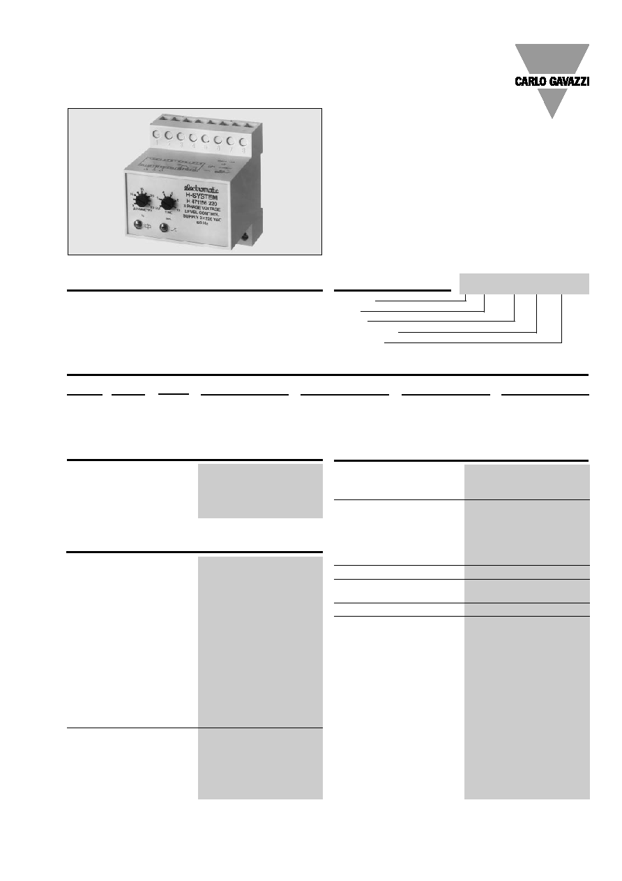
Current and Voltage Controls
Product Description
3-phase monitoring relay for
DIN-rail mounting for phase
sequence, phase loss, phase
asymmetry and phase angle.
Ordering Key
Housing
Type
Output
Power supply
Frequency
Type Selection
Plug
Output
Freq.
Supply: 220 VAC
Supply: 380 VAC
Supply: 400 VAC
Supply: 415 VAC
Screw
SPDT
50 Hz
H 471 156 220-50 Hz
H 471 156 380-50 Hz
H 471 156 400-50 Hz
H 471 156 415-50 Hz
terminals
60 Hz
H 471 156 220-60 Hz
H 471 156 380-60 Hz
H 471 156 400-60 Hz
H 471 156 415-60 Hz
∑ Mains network quality and load monitoring
relay
∑ Monitors phase sequence, phase loss, phase
asymmetry and phase angle
∑ Measures asymmetry on 3-ph. voltage without neutral
∑ Built-in adjustable timer function
∑ Knob-adjustable asymmetry sensitivity
∑ Output: 10 A SPDT relay
∑ For mounting on DIN-rail in accordance with
DIN/EN 50 022
∑ H4-housing
∑ LED-indication for power supply and output ON
∑ Power supply is the 3-phased measuring voltage
Input Specifications
Input
Terminal 22
Phase L3
Terminal 23
Phase L2
Terminal 24
Phase L1
measures on own supply
Output
SPDT relay
Rated insulation voltage
250 VAC (rms)
(cont./elect.)
Contact ratings (AgCdO)
µ (micro gap)
Resistive loads
AC 1
10 A/250 VAC (2500 VA)
DC 1
1 A/250 VDC (250 W)
or
10 A/25 VDC (250 W)
Small inductive loads AC 15
2.5 A/230 VAC
DC 13
5 A/24 VDC
Mechanical life
30 x 10
6
operations
Electrical life
AC 1
2.5 x 10
5
operations
(at max. load)
Operating frequency
7200 operations/h
Dielectric strength
Dielectric voltage
2 kVAC (rms) (cont./elect.)
Rated impulse withstand volt.
4 kV (1.2/50 µs) (cont./elect.)
(IEC 60664)
Power supply AC types
Overvoltage cat. III (IEC 60664)
Rated operational voltage
(IEC 60038)
Through term. 22, 23 & 24
220
3 x 220 VAC ± 15%,
50 or 60 Hz
380
3 x 380 VAC ± 15%,
50 or 60 Hz
400
3 x 400 VAC ± 15%,
50 or 60 Hz
415
3 x 415 VAC ± 15%,
50 or 60 Hz
Voltage interruption
40 ms
Dielectric voltage
None (supply/elect.)
Rated impulse withstand volt. 4 kV (1.2/50 µs) (line/neutral,
line/line), direct connection
to electronics
Rated operational power
3 VA
Often used to control phase
asymmetry in order to pre-
vent any damage to the con-
nected motors.
3-Phase Asymmetrical Relay
Type H 471
Output Specifications
Supply Specifications
H 471 156 380-50 Hz

2
Specifications are subject to change without notice (26.10.99)
H 471
Reaction time
= 0.2 s, worst case reaction
time may be up to 5 x
Adjustable delay on release
built-in (0.2 s - 10s)
Note:
Reaction time + set time =
actual delay on release time
Accuracy
OFF delay
10 s, -1/+3 s on max.
< o.1 s on min.
Time function
Delay on release 0.2-10 s. adj.
Indication for
Power supply ON
LED, green
Output ON
LED, red
Environment
(IEC 60947-1)
Degree of protection
IP 20 B/front IP 40 D (IEC 60529)
Pollution degree
3 (IEC 60664)
Operating temperature
-20∞ to +50∞C (-4∞ to +122∞F)
Storage temperature
-50∞ to +85∞C (-58∞ to +185∞F)
Weight
300 g
Approval
CSA
Mode of Operation
Applications of asymmetry
I: Mains monitoring:
Phase sequence.
Phase loss.
Phase amplitude asymme-
try.
II:Load monitoring:
Phase sequence (direction
of motor rotation).
Fuse blowing.
Example 1
Mains network monitoring
The relay measures phase
loss, that the power supply has
correct phase sequence, that
all three phases are present,
and that the phase asymme-
try is within the preset level.
The knob-adjustable H 471
detects phase asymmetries
of 2 to 12% of phase-phase
amplitude.
The relay operates when all
three phases are present at
the same time and the phase
sequence is correct as well
as the measured asymmetry/
unbalance is below set point
(2 to 12% of phase asymme-
try). Phase angle failures are
registered as phase asymme-
try.
If the supply voltage drops to
approx. 25% of the phase-
phase voltage, the relay re-
leases without time delay.
Time/Range Setting
Range setting
Left potentiometer:
Phase asymmetry sensitivity
2 to 12% of phase-phase
amplitude. Adjustable on ab-
solute scale.
Time setting
Right potentiometer:
Time setting on relative scale.
Adjustable delay on release:
0.2 to 10 s.
Wiring Diagrams
Example 1
H 471
Example 2
H 471
µ
µ
L3
L2
L1
L3
L2
L1
General Specifications
regenerated phase depends
on the actual mechanical load
and motor size. In this case it
is a combination of phase
amplitude and phase angle
asymmetry higher than 2-3%.
Setting
Turn the asymmetry potentio-
meter counterclockwise (from
max.) until the relay releases.
Continue adjusting approx. 1
mark clockwise to ensure cor-
rect operation. At approx. 5%
or less asymmetry, ensure
that possible power supply
variations do not result in er-
roneous release.
Setting
The allowed asymmetry for
the mains voltage amplitudes
is set on the potentiometer.
Example 2
Load monitoring
The 3-phased monitoring re-
lay for electrical loads ensures
correct starting and operat-
ing conditions. The relay mo-
nitors phase sequence and
consequently the correct di-
rection of motor rotation.
The most frequent cause of
asymmetry and unbalance is
fuse blowing. In this case the
motor regenerates the inter-
rupted phase. The size of the
