 | –≠–ª–µ–∫—Ç—Ä–æ–Ω–Ω—ã–π –∫–æ–º–ø–æ–Ω–µ–Ω—Ç: RSB4015-B | –°–∫–∞—á–∞—Ç—å:  PDF PDF  ZIP ZIP |
Specifications are subject to change without notice (12.12.2005)
1
Ordering Code
Motor Controller
AC Semiconductor Motor Controller
Types RSB..15-B
RSB 40 15 - B
∑
Soft starting and stopping of 3-phase
squirrel cage motors
∑
Board-level solution
∑
Rated operational voltage: up to 480 VACrms, 50/60 Hz
∑
Rated operational current: 15 AAC 53 b
∑
Transient overvoltage protection built-in
∑
Integral bypassing of semiconductors
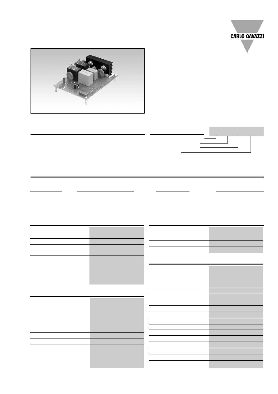
Product Description
Easy-to-use AC semi-
conductor motor controller.
With this controller 3-phase
motors with nominal
load currents up to 15 A can
be soft-started and/or soft-
stopped. Starting and stop-
ping time as well as initial
torque can be independently
adjusted by built-in poten-
tiometers.
Board level Motor Controller
Rated operational voltage
Rated operational current
Control voltage
Input Specifications (Control Input)
Control voltage U
c
A1-A2:
200...300VAC, 5 mA
Rated AC frequency
50/60 Hz -5/+5Hz
Rated insulation voltage
630 V rms
Overvoltage cat. III (IEC 60664)
Dielectric strength
Dielectriv voltage
2 kVAC (rms)
Rated impulse withstand volt. 4 kV (1.2/50 µs)
Type Selection
Type
Rated operational
Rated operational
Control voltage
voltage U
e
Current I
e
U
c
*)
RSB: Board level
22: 127/220 VACrms, 50/60Hz
15: 15AAC
-B: 200...300VAC, 5 mA
Motor Controller
40: 230/400 VACrms, 50/60Hz
48: 277/480 VACrms, 50/60Hz
Output Specifications
Utilization category
AC-53b Integral bypassing
of semiconductors
Overload current profile
15A: AC-53b:3-3:300
Min. load current
200 mAAC rms
Power supply
Overvoltage cat. III (IEC 60664)
Rated operational volt. (U
e
)
through terminals L1-L2-L3
(IEC 60038)
22
127/220 VACrms ± 15%
40
230/400 VACrms ±15%
48
227/480 VACrms ± 15%
Rated AC frequency
50/60 Hz -5/+5 Hz
Voltage interruption
40 ms
Dielectric strength
Dielectriv voltage
2 kVAC (rms)
Rated impulse withstand volt. 4 kV (1.2/50 µs)
Accuracy
Ramp up
6.5 sec ± 10% on max.
Ramp down
8 sec ± 10% on max.
Initial torque
0 to 85% ± 10%
Equipment class
A
EMC Immunity
Electromagnetic Compatibility
acc. to EN 61000-6-2
Operating temperature
-20∞ to +50∞C (-4∞ to +122∞F)
Storage temperature
-50∞ to +85∞C (-58∞ to +185∞F)
Control FASTON terminals
4.8 x 0.5 mm
Power FASTON terminals
6.3 x 0.8 mm
Approvals
UL, cUL compliant
CE marking
Yes
Norms
IEC/EN 60947-4-2
Form designation
Form 1
Degree of protection
IP00
Pollution Degree
2
Supply Specifications
General Specifications
2
Specifications are subject to change without notice (12.12.2005)
External Protection
RSB
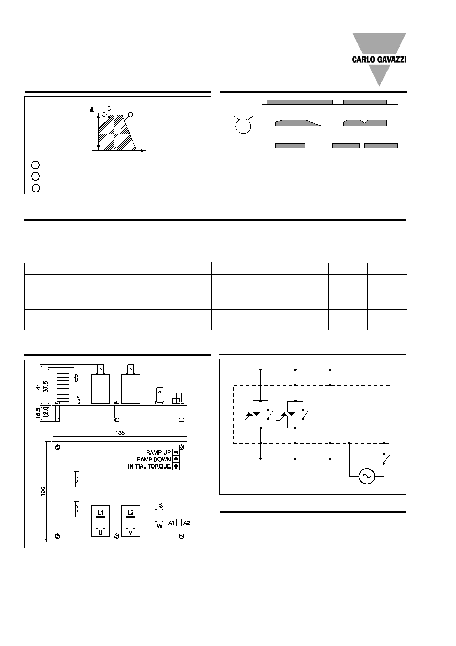
Operation Diagram 2
Operation Diagram 1
Time (s)
Motor voltage
100%
35%
0.8
1
Ramp-up time 6.5s±10%. Time from zero load voltage to full load
voltage.
Ramp-down time 8.0s±10%. Time from full load voltage to zero
load current.
Initial torque 0 to 85% voltage at the start of the ramp-up function.
2
3
1
2
3
Mains Ue
Control input Uc
Dimensions
Mode of Operation
This motor controller is intend-
ed to be used to soft-start 3-
phase compressor induction
motors and can reduce the
starting currents of the system
by up to 40%. Soft-starting is
achieved by controlling the
motor voltage. During running
operation the semiconductors
are bypassed by electrome-
chanical relays.
The device rating is based on
12 starts per hour but this can
be higher depending on the
application. The controller is
switching 2 lines. The 3rd line
is continuously connected to
the load. Overload protection
is not provided in this motor
controller and must therefore
be installed separately.
M
3~
Motor full load current (AACrms)
Overload relay type
Telemecanique: GV 2-
Overload relay type
ABB:MS 325-
Motor protection circuit breaker type
Allan-Bradley: KTA 3-25-
2.5 - 4
4 - 6.3
6.3 - 9
9 - 12.5
12 - 15
M 08
M 10
M 14
M 16
M16
M20
4
6.3
9
12.5
12.5
16
4
6.3
10
16
16
2. Recommended motor protection circuit breakers
1. Recommended semiconductor protection fuses
Type: 6.621 CP URQ 27x60 / 50, Ferraz Shawmut
L1
L2
L3
U/T1
V/T2
W/T3
A1
A2
S1
Connection Diagram
RSHP
M
3~
K
Fuse
Contactor
Overload
RSHP
M
3~
Motor
protection
relay
A1
A2
Stop
Start
K
K
A1
A2
1
L1
3
L2
5
L3
2
T1
4
T2
6
T3
M
3 ~
K
K
K
Specifications are subject to change without notice (12.12.2005)
3
RSB
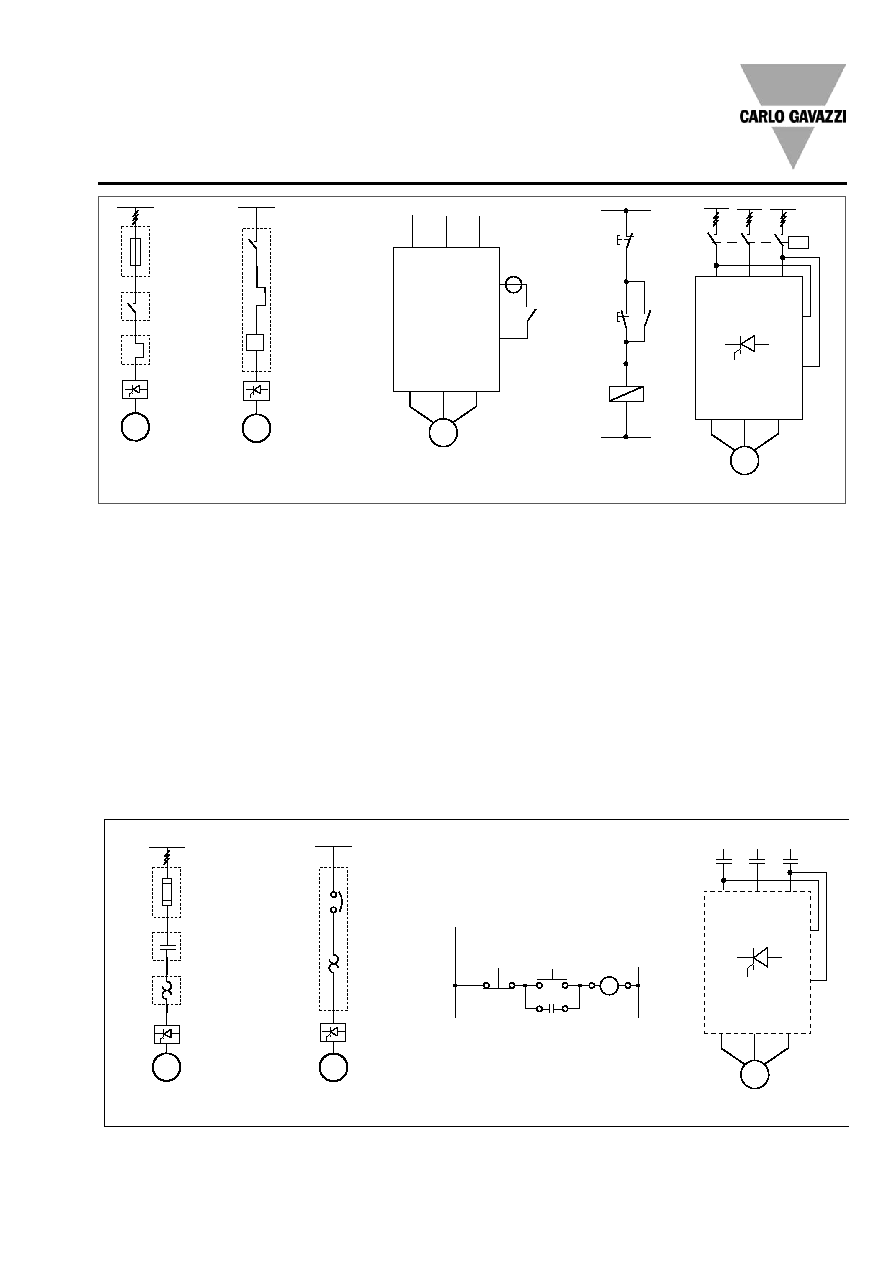
Figure 5: Control using 2
phases
Connecting input A1, A2 to
two of the incomming lines
will soft start the motor when
K is operated. When K is
switched off, the motor will
stop (no soft stop).
This method of control is only
valid for model RSB2215-B
as max. Control voltage
allowed across A1, A2 is
300VAC.
Wiring Diagrams
The motor controller provides
by-passing of the semicon-
ductors during running opera-
tion. Therefore the semicon-
ductors can only be damaged
by short-circuit currents dur-
ing ramp-up and ramp-down.
Please note that the motor
controller does not insulate
the motor from the mains.
Figure 1: Protection of the
device when using fuses.
Protection with semiconduc-
tor fuses is intended to pro-
tect the motor feeder and
motor controller from damage
due to short-circuit.
Figure 2: Protection using a
thermal-magnetic motor
protection relay.
The motor feeder is protected
but damage to the motor con-
troller is possible. When motor
failure occurs, if part of the
motor winding limits the fault
current and the motor feeder
is protected, this type of pro-
tection can be considered
acceptable.
Figure 3: Control using a 2-
position switch.
When K is closed, the control
input is supplied to A1, A2
and soft starting of the motor
is performed. When K is
opened, soft stopping is per-
formed.
Figure 4: Control using ON
and OFF push buttons
Pushing S1 soft starts the
RSB. Pushing S2 soft stops
the RSB. K is an auxiliary con-
tact of the mains contactor.
Fig. 1a
Fig. 2a
Fig. 3
Fig. 4a
Fig. 5a
Fig. 1b
Fig.2b
Fig. 4b
Fig. 5b
RSHP
M
3~
K
Fuse
Contactor
Overload
I>
RSHP
M
3~
Motor
protection
relay
A1
A2
L1
L2
L3
U/T1 V/T2 W/T3
K
M
3 ~
K
K
S1(ON)
S2(OFF)
A1
A2
A1
A2
L1
L2
L3
U/T1 V/T2 W/T3
K
M
3 ~
RSB
RSB
RSB
RSB