Specifications are subject to change (30.09.2005)
1
H-line Motor Controller
Rotary Ramp profile setting
Rated operational voltage
Rated operational current
Control voltage
Options
Ordering Key
Motor Controllers
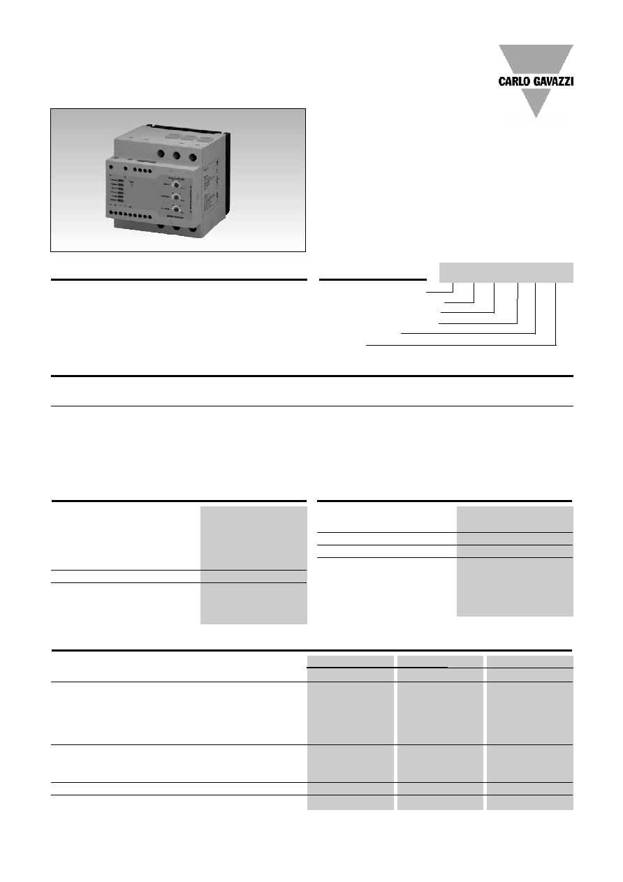
AC Semiconductor Motor Controller
Type RSHR
∑ Soft starting and stopping of 3-phase
squirrel cage motors
∑ Low inrush and reduced vibration during starting
∑ Integrated bypassing of semiconductors
∑ Rated operational voltage: up to 600 VAC, 50/60 Hz
∑ Rated operational current up to 45A AC-53b
∑ LED status indicators
∑ Motor PTC protection
∑ Device over-temperature protection
∑ DIN rail or panel mounting
Product Description
Compact easy-to-use AC
semiconductor motor con-
troller. With this controller 3-
phase motors with nominal
load currents up to 45 A can
be soft-started and/or soft-
stopped. Starting and stop-
ping time as well as initial
torque can be independently
adjusted by built-in poten-
tiometers.
RSH R
48
45 C V20
Supply Specification
Rated operational voltage
Ue through L1, L2, L3
RSHR22.. 127/220 VAC -15% /+10%
RSHR40.. 230/400 VAC -15% /+10%
RSHR48.. 277/480 VAC -15% /+10%
RSHR60.. 346/600 VAC -15% /+10%
Rated AC frequency
50/60 Hz±10%
Dielectric strength
Dielectric voltage
2 kV (rms)
Rated impulse withstand volt.
4 kV (1.2/50µs)
Input Specifications
Rated control input
C: 24-550 VAC/DC
voltage Uc, A1-A2:
D:24-600 +10% VAC/DC
Rated control input current
<1.5 mA
Rated AC frequency
50/60 Hz±10%
Dielectric strength
Dielectric voltage
2kVAC (rms)
Rated impulse withstand volt. 4kV (1.2/50 µs)
Load Ratings
RSHR..25....
RSHR..38....
RSHR..45....
IEC rated operational current Ie (AC-53b)
25 A
38A
45 A
Assigned motor rating @ 60∫C/ UL rating @ 60∫C
RSHR22..
5.5kW / 10HP
11kW / 10HP
11kW / 15HP
RSHR40..
11kW / 15HP
18.5kW / 20HP
22kW / 25HP
RSHR48..
15kW / 20HP
22kW / 25HP
30kW / 30HP
RSHR60..
18.5kW / 25HP
22kW / 30HP
30kW / 40HP
Overload cycle according to IEC/EN 60947-4-2 @ 40∞C
25A:AC-53b:4-5:65 38A: AC-53b: 4-5:85
45A: AC-53b: 4-5: 115
@ 50∞C
25A:AC-53b:4-5:85 38A:AC-53b:4-5:175
45A: AC-53b: 4-5: 135
@ 60∞C
25A:AC-53b:4-5:175 38A:AC-53b:4-5:355
45A: AC-53b: 4-5: 175
Number of starts per hour @ 40∫C/50∞C/60∞C
50/35/20
40/20/10
30/25/20
Minimum load current
500mA
500mA
500mA
Rated operational
Rated operational current I
e
Options
voltage U
e
25A AC-53b
38A AC-53b
45A AC-53b
220VACrms
RSHR2225CV20
RSHR2238CV20
RSHR2245CV20
V20: Basic
400VACrms
RSHR4025CV20
RSHR4038CV20
RSHR4045CV20
V21: 2 auxiliary relays
480VACrms
RSHR4825CV20
RSHR4838CV20
RSHR4845CV20
600VACrms
RSHR6025DV20
RSHR6038DV20
RSHR6045DV20
Selection Guide
2
Specifications are subject to change (30.09.2005)
Line conductors:
L1, L2, L3/T1, T2, T3
according to IEC
60947
0.75...16mm
2
maximum size
solid
1.5...16mm
2
finely stranded with end sleeve 1.5...16mm
2
stranded
1.5...25mm
2
UL/CSA rated data
UL rated data
AWG 14...4
CSA rated data
AWG 14...6
Terminal screws
6xM5 (cage clamp)
Tightening torque
1.5...2.5 Nm /13...22 lb.in
CSA data
max. 3.0Nm/ 26.5 lb/in
Stripping length
10 mm
Secondary conductors:
A1, A2, 11, 21, 22, P1, P2
according to IEC 60947
0.75...2.5mm
2
maximum size
0.5...2.5mm
2
UL/CSA rated data
AWG 22...14
Terminal screws
7xM3 (cage clamp)
Tightening torque
0.3...0.5 Nm/2.7...4.5 lb.in
Stripping length
6 mm
RSHR
General Specifications
Pollution degree
3
Weight
800g (approx.)
Degree of protection
IP20 (IEC 60529)
Relative humidity
<95% non-condensing
Ramp up time
1...10s
Ramp down time
1...30s
Initial torque
0...70%
Status indicator LEDs
Power supply ON
LED, green (continuous)
Ramping
LED, yellow (intermittent)
Bypass relay ON
LED, yellow (continuous)
Over-temperature alarm
Device alarm
LED, red (intermittent)
Motor PTC alarm
LED, red (continuous)
Wrong phase sequence*
LED, red (intermittent)
Phase loss
Phase loss alarm*
LED, red (blinking at 4Hz)
Under voltage alarm
LED, red (blinking at 1.3Hz)
Motor PTC alarm input P1, P2 Acc. to DIN 44081 and
DIN 44082-1
Form designation
Form 1
Auxiliary relays: (V21 option)
Bypass relay activation
Normally open (21,22)
Over-temperature, phase
sequence, phase loss alarm Normally closed (11, 22)
Auxiliary relay contact capacity 3 A, 250 VAC
3 A, 30 VDC
Installation altitude
Above 1000m derate linearly
by 1% of unit FLC per 100m
to a maximum altitude of
2000m
Conductor Data
Standards
Approvals
UL, cUL, CSA
Markings
CE
Norms
IEC/EN 60947-4-2
Thermal Specifications
Operating temperature
-20∫ to +60∫C (-4∫ to +140∫F)
Storage temperature
-50∫ to +85∫C (-58∫ to +185∫F)
* detection of these alarm conditions is made during power-up of the device
Recommended Protection according to IEC/EN 60 947-4-2
RSHR..25....
RSHR ..38....
RSHR..45....
Type of coordination: 2
Semiconductor fuse
Ferraz Shawmut
Ferraz Shawmut
Ferraz Shawmut
63A, Class URQ,
80A, Class URQ,
100A, Class URQ,
Art.No. 6.621
Art.No. 6.621
Art.No. 6.621
CP URQ27x60/63
CP URQ27x60/80
CP URQ27x60/100
Type of coordination: 1
Motor protection circuit breaker
ABB: MS325 -25
ABB: MS450 -40
ABB: MS450 -45
Telemecanique:
Telemecanique: Telemecanique:
GV2-M22
GV3-ME40
GV3-ME63
Sprecher+Schuh: Sprecher+Schuh: Sprecher+Schuh:
KTA3-25-25A
KTA3-100-40A
KTA3-100-63A
RK5 fuse
TRS45R 45A
TRS70R 70A
TRS90R 90A
Specifications are subject to change (30.09.2005)
3
IEC
NEMA
RSHR
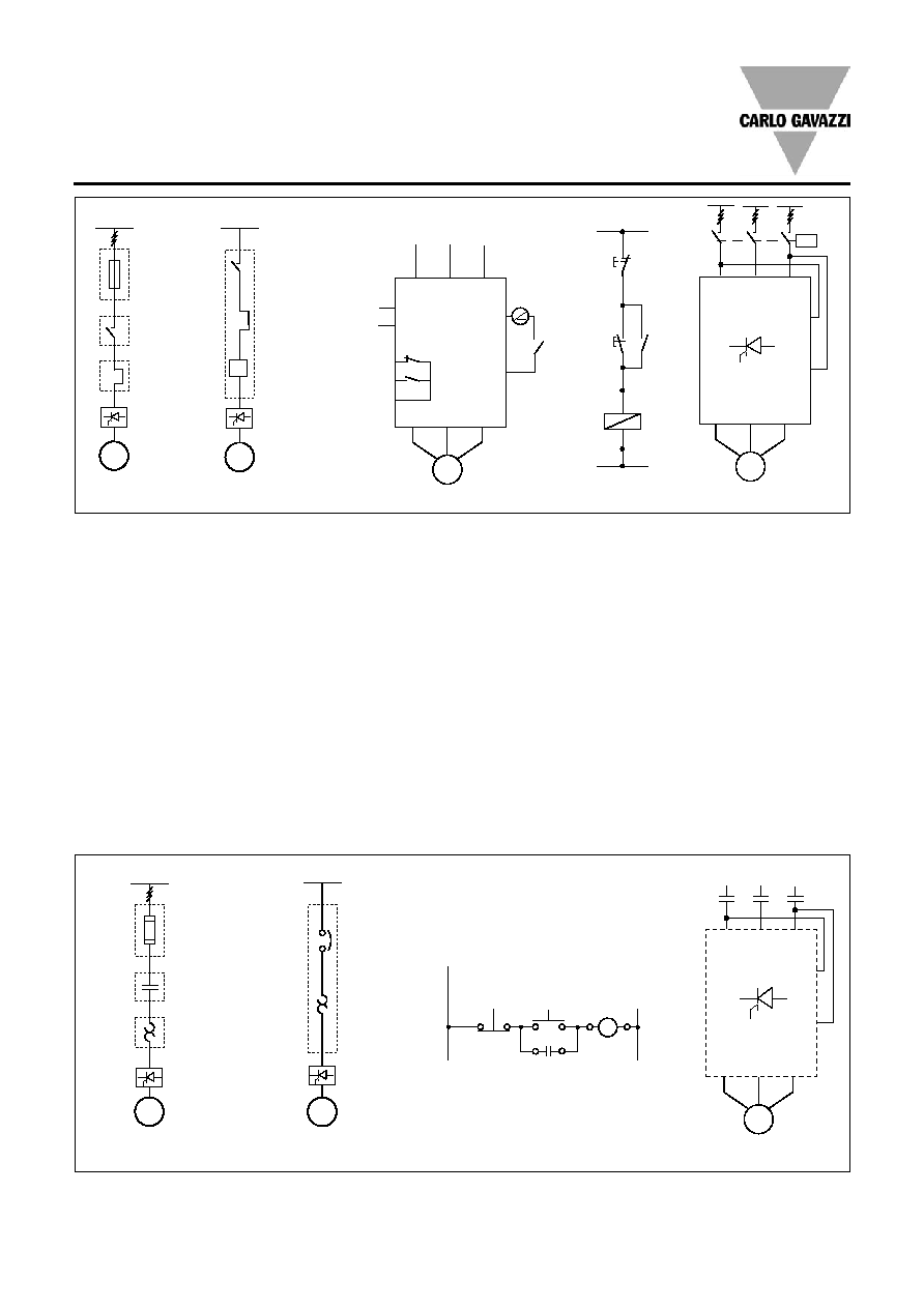
to the coil of an external
bypass contactor.
Figure 4: Control using ON
and OFF push buttons
Pushing S1 soft starts the
RSHR. Pushing S2 soft stops
the RSHR. K is an auxiliary
contact of the mains contactor.
Figure 5: Control using 2
phases
Connecting input A1, A2 to
two of the incomming lines
will soft start the motor when
K is operated. When K is
switched off, the motor will
stop (no soft stop).
Wiring Diagram
The motor controller provides
by-passing of the semicon-
ductors during running opera-
tion. Therefore the semicon-
ductors can only be damaged
by short-circuit currents dur-
ing ramp-up and ramp-down.
Please note that the motor
controller does not isolate the
motor from the mains.
Figure 1: Protection of the
device when using fuses.
Protection with semiconduc-
tor fuses is intended to pro-
tect the motor feeder and
motor controller from damage
due to short-circuit.
Figure 2: Protection using a
thermal-magnetic motor
protection relay.
The motor feeder is protected
but damage to the motor con-
troller is possible. When motor
failure occurs, if part of the
motor winding limits the fault
current and the motor feeder
is protected, this type of pro-
tection can be considered
acceptable.
Figure 3: Secondary con-
ductors.
3.1: Control using a 2-position
switch.
When K is closed, the control
input is supplied to A1, A2
and soft starting of the motor
is performed. When K is
opened, soft stopping is per-
formed.
3.2: Motor PTC input
When the motor PTC sensor
is connected to P1, P2 the
motor controller detects over-
heating of the motor windings.
3.3: Auxiliary Relays (Available
on RSHR...
V21
types only!)
The Alarm relay 11, 22 (NC)
can be connected in series
with the supply to the coil of a
mains contactor. The Bypass
ON relay 21, 22 (NO) can be
used in series with the supply
RSHP
M
3~
K
Fuse
Contactor
Overload
I>
RSHP
M
3~
Motor
protection
relay
A1
A2
L1
L2
L3
U/T1 V/T2 W/T3
P1
P2
Motor
PTC
input
11
21
22
Alarm
Bypass ON
Common
K
M
3 ~
~
---
K
K
S1(ON)
S2(OFF)
A1
A2
A1
A2
L1
L2
L3
U/T1 V/T2 W/T3
K
M
3 ~
Fig. 1a
Fig. 2a
Fig. 3a
Fig. 4a
Fig. 5a
RSHP
M
3~
K
Fuse
Contactor
Overload
RSHP
M
3~
Motor
protection
relay
A1
A2
Stop
Start
K
K
A1
A2
1
L1
3
L2
5
L3
2
T1
4
T2
6
T3
M
3 ~
K
K
K
Fig. 1b
Fig. 2b
Fig. 4b
Fig. 5b
RSHR
RSHR
RSHR
RSHR
4
Specifications are subject to change (30.09.2005)
RSHR
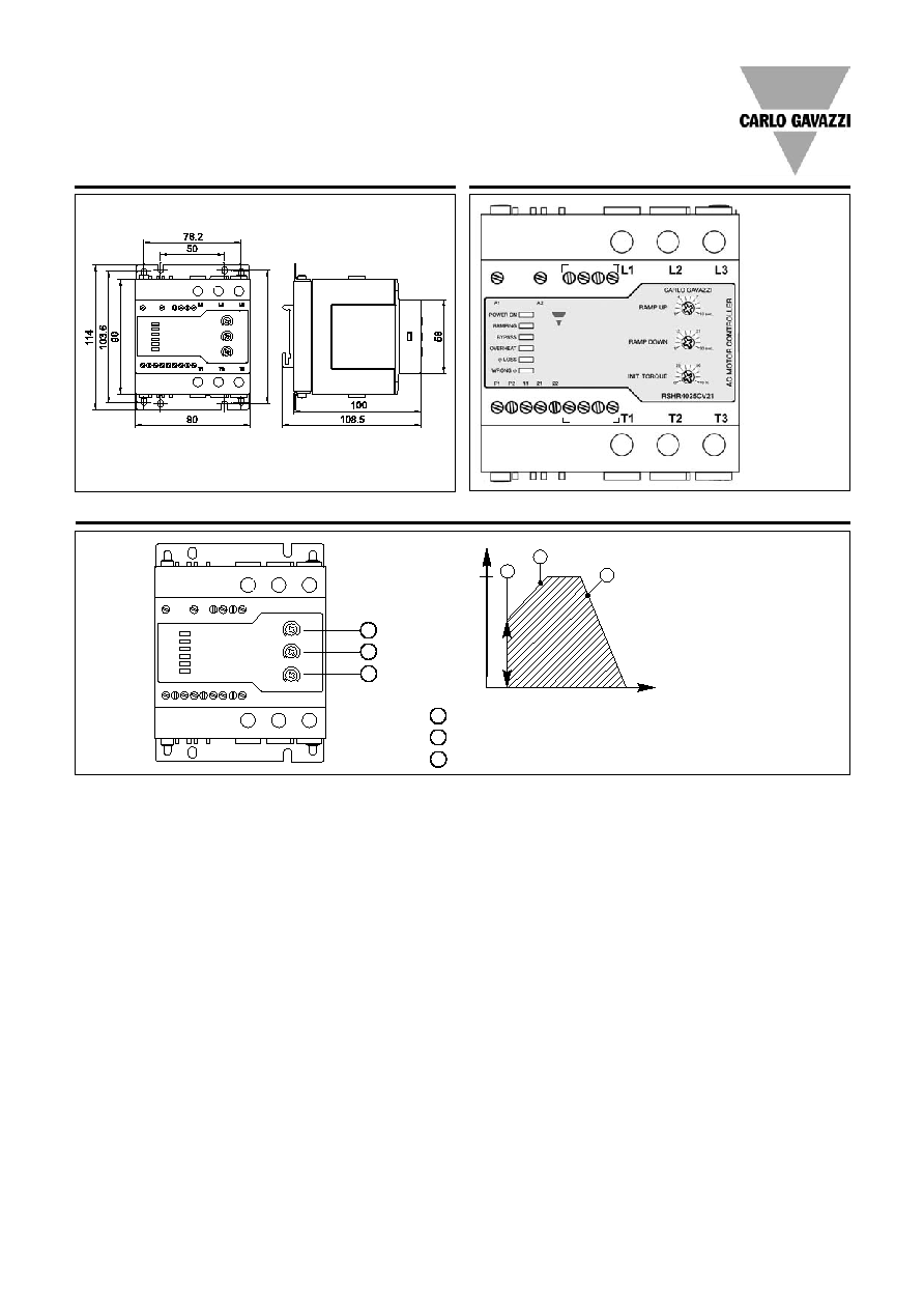
Dimensions
All dimensions in mm
Terminal Diagram
Operation Diagram
3
1
2
100%
Motor voltage
Time
1
Ramp-up time 1 to 10 s. Time from zero load voltage to full load voltage.
2
Ramp-down time 1 to 30 s. Time from full load voltage to zero load voltage.
3
Initial torque 0 to 70% voltage at the start of the ramp-up function.
1
2
3
A1, A2:Control input
P1, P2:PTC input
11, 22: Alarms (NC)
21, 22: Bypass relay
activation (NO)
Note: Relay termi-
nals 11,21,22 are
not used in
RSH
R
...V20
not used
not used
Specifications are subject to change (30.09.2005)
5
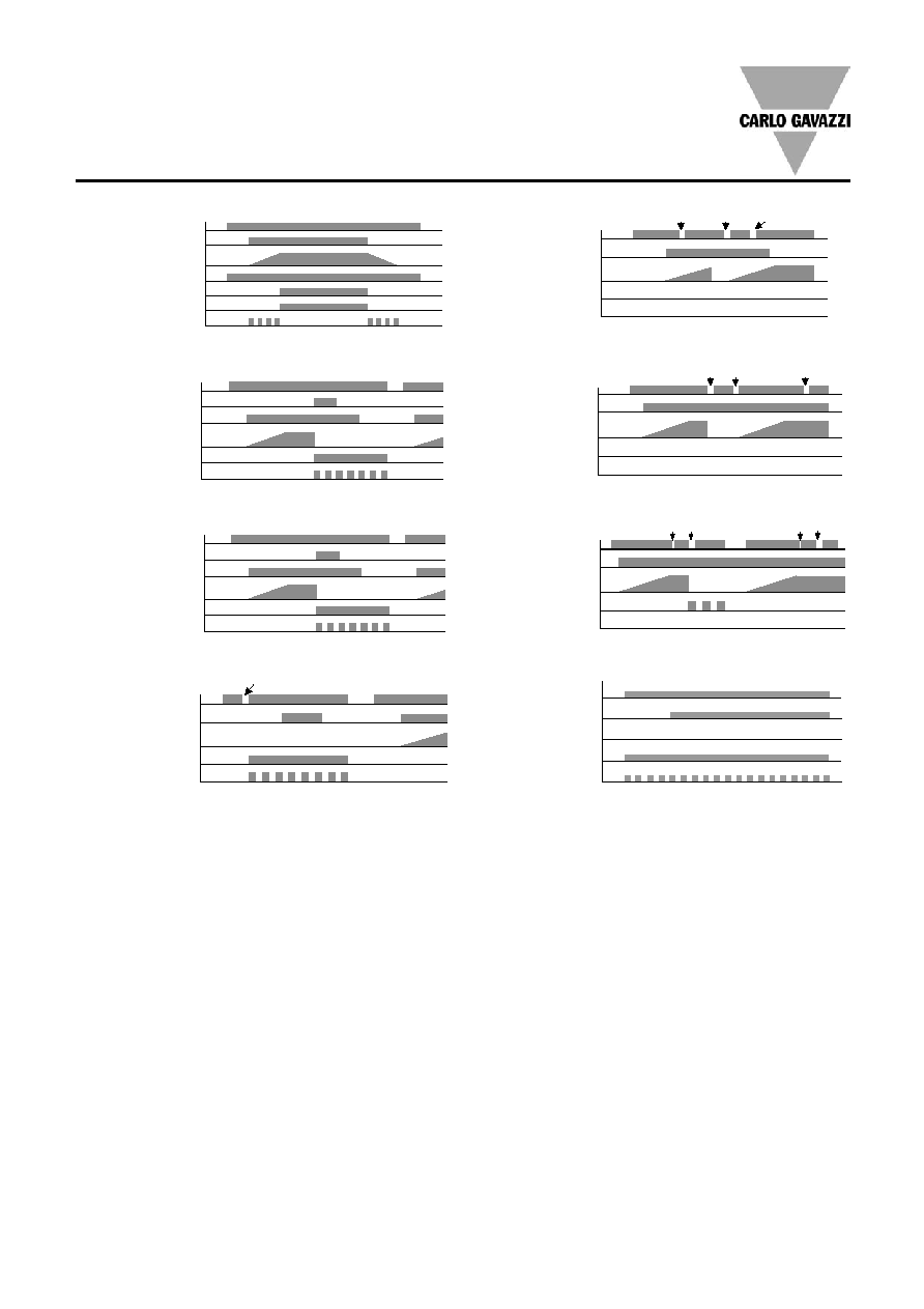
Operation Diagrams for RSHR
Notes
Note1: After activation of the by-pass relay, there is a delay of 1 sec, during
which removal of the control input will not initiate the ramp-down function.
Note 2: Cycling of the control input should be limited to a rate not exceeding 3
seconds ON and 3 seconds OFF. At faster cycling times, it is not guaranteed that
the output of the unit will respond to the given input.
Important: The number of starts per hour and Overload Cycle values should
always be taken into consideration when cycling is used.
Note 3: Auxiliary relays available only on RSHR...V21 types
Note 4
:
A phase loss on L1 or L2 causes the device to reset as these phases
provide the internal power supply.
Note 5: Phase sequence and phase loss alarms are only detected if they occur
during power up, when L1, L2, L3 are switched ON.
Note 6: When a motor PTC is connected, electromagnetic noise may be con-
ducted into the unit. Thus if abnormal function is observed, the use of ferrite
beads on the PTC wire (at the unit end) is recommended.
Note 7: Repetitive voltage dips on phase L1 and/or L2 during operation may
lead to overheating of the motor. In case the by-pass relays are activated and
the repetition rate of these dips is such that the internal supply voltage falls
below a preset limit, the by-pass relays will be automatically switched off.
This state is indicated by blinking of the phase loss led at 1.3Hz. Reset of the
supply L1, L2 and L3 is necessary to resume normal function.
Mains Supply L1, L2, L3
Diagram 1: Normal Operation
Control Input Uc
Motor Supply T1, T2, T3
Power ON-LED
Bypass ON auxiliary relay
Bypass ON LED
Ramping LED
Mains Supply L1, L2, L3
Diagram 2a: Device over-temperature alarm
Device over-temperature
Control Input Uc
Motor supply T1, T2, T3
Alarm auxiliary relay
Overheat alarm LED
Mains Supply L1, L2, L3
Diagram 2b: Motor PTC alarm
Motor PTC over-temperature
Control Input Uc
Motor supply T1, T2, T3
Alarm auxiliary relay
Overheat alarm LED
Mains Supply L1, L2, L3
Diagram 2c: Phase loss during power up
Control Input Uc
Motor supply T1, T2, T3
Alarm auxiliary relay
Phase loss alarm LED
L3 Loss
Mains Supply L1, L2, L3
Diagram 2d: Phase loss during ramping
Control Input Uc
Motor supply T1, T2, T3
Alarm auxiliary relay
Phase loss alarm LED
L1/L2 loss
L1/L2 resume
L3 loss
Mains Supply L1, L2, L3
Diagram 2e: Phase loss while bypass is ON
Control Input Uc
Motor supply T1, T2, T3
Alarm auxiliary relay
Phase loss alarm LED
L1/L2 loss
L1/L2 resume
L3 loss
Mains Supply L1, L2, L3
Diagram 2f: Phase loss while bypass is being activated
Control Input Uc
Motor supply T1, T2, T3
Alarm auxiliary relay
Phase loss alarm LED
L1/L2 loss
L1/L2 resume
L3 loss
L3 resume
Mains Supply L1, L2, L3
Diagram 2g : Wrong phase sequence alarm
Control Input Uc
Motor supply T1, T2, T3
Wrong
alarm LED
Alarm auxiliary relay
wrong phase sequence