Specifications are subject to change (03.08.2006)
1
H-line Motor Controller
Rotary Ramp profile setting
Rated operational voltage
Rated operational current
Control voltage
Options
Ordering Key
Motor Controllers
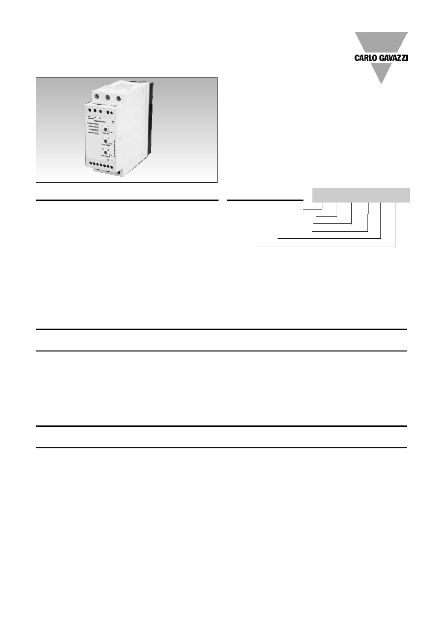
AC Semiconductor Motor Controller
Type RSHR MIDI
∑ Soft starting and stopping of 3-phase
induction squirrel cage motors
∑ 2-phase control with integral bypassing of
semiconductors
∑ Low inrush and reduced vibration during starting
∑ Rated operational voltage: up to 600 VAC, 50/60Hz
∑ Rated operational current: up to 18A AC-53b
∑ Multivoltage option with a range of 190 - 530 VAC*
∑ LED status indicators
∑ Optional device over-temperature protection
∑ Optional auxiliary relay for end of ramp
∑ DIN rail mounting
* requires external supply
Product Description
The RSHR Midi is a compact
easy-to-use AC semiconduc-
tor motor controller. With this
controller 3-phase motors
with nominal currents up to
18A can be soft started
and/or soft stopped. The
RSHR Midi controls 2 phases
only, one phase is continously
connected to the load. Soft
starting and soft stopping is
achieved by controlling the
motor voltage. During running
operation the semiconductors
are bypassed by internal elec-
tromechanical relays. Starting
and stopping time as well as
initial torque can be indepen-
dently adjusted by built-in
potentiometers.
LEDs indicate the status of
the controller including an
alarm status in case of over-
temperature in the RSHR...V21
models. The RSHR Midi
comes with an integrated
heatsink and is ready to
mount on DIN rail.
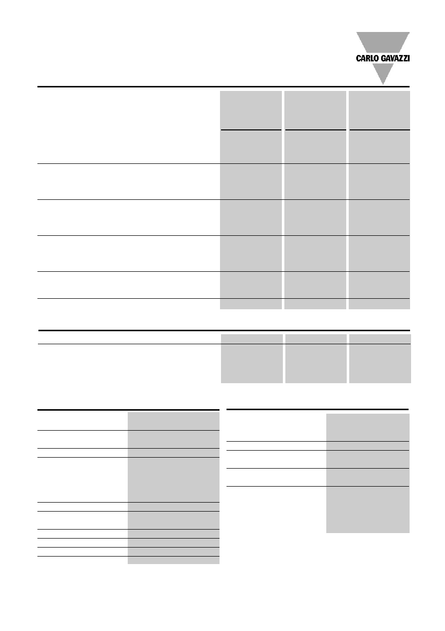
RSH R 48 18 B V21
Rated operational
Rated operational current I
e
voltage U
e
6A AC-53b
12A AC-53b
18A AC-53b
220VACrms
RSHR2206BV20
RSHR2212BV20
RSHR2218BV20
400VACrms
RSHR4006BV20
RSHR4012BV20
RSHR4018BV20
480VACrms
RSHR4806BV20
RSHR4812BV20
RSHR4818BV20
600VACrms
RSHR6006BV20
RSHR6012BV20
RSHR6018BV20
190-530VACrms
RSHRM06BV20
RSHRM12BV20
RSHRM18BV20
Selection Guide
Type
Rated Operational
Rated Operational
Control Voltage
Options
Voltage Ue
Current Ie
Uc
RSHR: H-line
22: 127/220VACrms, 50/60Hz
06: 6A AC-53b
B: 24 to 110VAC/DC
V20: Basic
motor controller
40: 230/400VACrms, 50/60Hz
12: 12A AC-53b
& 110 to 480VAC
V21: End of Ramp
with rotary settings
48: 277/480VACrms, 50/60Hz
18: 18A AC-53b
Relay & Over-
60: 346/600VACrms, 50/60Hz
Temperature
M: 190-530VACrms, 50/60Hz
Protection
Type Selection
2
Specifications are subject to change (03.08.2006)
RSHR MIDI
General Specifications
Ramp up time
0.5...10s
+/- 1.5s on max.
Ramp down time
0.5...20s
+/- 4s on max.
Initial torque
0...85%
Status indicator LEDs
Power supply ON
LED, green
Ramping
LED, yellow
Bypass relay ON
LED, yellow
Over-temperature alarm*
LED, red
Auxiliary relay*
Normally open (11, 12)
Auxiliary relay contact capacity* 3A, 250VAC
3A, 30VDC
Form designation
1
Weight
800g (approx.)
Mounting
DIN Rail 35mm
Housing material
Polyamide
Load Ratings
RSHR22..BV..
RSHR2218BV..
RSHR40..BV..
RSHR4018BV..
RSHR48..BV..
RSHR4818BV..
RSHRM..BV..
RSHRM18BV..
RSHR60..BV..
IEC rated operational current Ie (AC-53b)
RSHR..06....
6A
6A
RSHR..12...
12A
12A
RSHR..18...
18A
18A
Overload cycle according to EN/IEC 60947-4-2
@ 40∞C surrounding temp.
RSHR..06...
6A: AC-53b:4-5:4
6A: AC-53b: 4-5:3
RSHR..12...
12A: AC-53b:4-5:50
12A: AC-53b:4-5:14
RSHR..18..
18A: AC-53b:4-5:50 18A: AC-53b:4-5:50
Overload cycle according to EN/IEC 60947-4-2
@ 50∞C surrounding temp.
RSHR..06...
6A: AC-53b:4-5:26
6A: AC-53b: 4-5:8
RSHR..12...
12A: AC-53b:4-5:62
12A: AC-53b:4-5:26
RSHR..18..
18A: AC-53b:4-5:62 18A: AC-53b:4-5:62
Overload cycle according to EN/IEC 60947-4-2
@ 60∞C surrounding temp.
RSHR..06...
6A: AC-53b:4-5:62
6A: AC-53b: 4-5:26
RSHR..12...
12A: AC-53b:4-5:80
12A: AC-53b:4-5:50
RSHR..18...
18A: AC-53b:4-5:110
18A: AC-53b:4-5:110
Number of starts per hour @40/50/60∞C
RSHR..06...
250/ 100/ 50
275/ 200/ 100
RSHR..12...
60/50/40
150/ 100/ 60
RSHR..18...
60/ 50/ 30
60/ 50/ 30
Minimum load rating
0.25kW
0.25kW
0.25kW
Motor Ratings
IEC rated operational current Ie (AC-53b)
6A
12A
18A
Assigned motor rating @60∞C/UL rating @60∞C 220VACrms 1.1kW/ 1.5HP
3kW/ 3HP
4kW/ 5HP
400VACrms 2.2kW/ 3HP
5.5kW/ 7.5HP
7.5kW/ 10 HP
480VACrms 2.2kW/ 5HP
5.5kW/ 7.5HP
7.5kW/ 10HP
600VACrms 3kW/ 5HP
7.5kW/ 10HP
11kW/ 15HP
Input Specifications
Rated control input voltage Uc
A1:A2
24 - 110VDC/AC
A1:A3
110 - 480VAC
Rated AC frequency
50/60Hz +/-10%
Max. control input current A1:A2
5mA
A1:A3
5mA
Min. control input current A1:A2
1mA
A1:A3
1mA
Dielectric strength
Dielectric withstand voltage
Input to heatsink
3.5 kVrms
Rated impulse withstand voltage 6 kV (1.2/50us)
Specifications are subject to change (03.08.2006)
3
Line conductors:
L1, L2, L3, T1, T2, T3
according to EN 60947-1
flexible
2.5 ..... 10mm
2
2.5 ..... 2 x 4mm
2
rigid (solid or stranded)
2.5 ..... 10mm
2
flexible with ferrule
2.5 ..... 10mm
2
UL/CSA rated data
flexible
AWG14...8
AWG14...2 x 10
rigid (solid or stranded)
AWG14...8
Terminal screws
6xM4 (cage clamp)
Tightening torque
2.5Nm (22lb.in) with
Posidrive bit 2
Stripping length
8.0mm
Secondary conductors:
A1, A2, A3, A4, A5, 11, 12
according to EN 60998
flexible
0.5 ..... 1.5mm
2
flexible with ferrule
0.5 ..... 1.5mm
2
rigid (solid)
0.5 ..... 2.5mm
2
UL/CSA rated data
AWG22...12
Terminal screws
7xM3 (cage clamp)
Tightening torque
0.5Nm (4.5lb.in) with
Philips bit 0
Stripping length
6.0mm
Conductor Data
Environmental Specifications
Operating temperature
-20∞C to +60∞C
(-4∞F to +140∞F)
Storage temperature
-50∞C to +85∞C
(-58∞F to +185∞F)
Relative humidity
<95% non-condensing
@40∞C
Pollution Degree
3
Degree of Protection
IP20 (EN/IEC 60529)
Installation category
III
Installation Altitude
Above 1000m derate linearly
by 1% of unit FLC per 100m
to a maximum altitude of
2000m
Vibration
Sinosodial (IEC 60068-2-6)
13 to 25Hz: 2.0mm peak
25 to 150Hz: 20m/s
2
External Supply Specifications
External supply voltage Us,
A4:A5*
24VDC/AC -15% / +10%
Rated AC frequency
50/60Hz +/-10%
Maximum supply current
265mAAC, 140mADC
Minimum supply current
195mAAC, 100mADC
Dielectric strength
Dielectric withstand voltage
Supply to input
2.5 kVrms
Supply to heatsink
2.5 kVrms
Rated impulse withstand
voltage
6 kV (1.2/50us)
* Applicable to RSHRM models only
RSHR MIDI
Supply Specification
Rated operational voltage
Ue through L1, L2 L3 RSHR22.. 127/220VAC
-15% / +10%
RSHR40.. 230/400VAC
-15% / +10%
RSHR48.. 277/480VAC
-15% / +10%
RSHR60.. 346/600VAC
-15% / +10%
RSHRM
190-530VAC
Rated AC frequency
50/60Hz +/-10%
Rated insulation voltage
630V, accord. to
EN 60947-1
Dielectric strength
Dielectric withstand voltage
Supply to input
4 kVrms
Supply to heatsink
4 kVrms
Supply to external supply
2.5 kVrms
Rated impulse withstand voltage 6 kV (1.2/50us)
4
Specifications are subject to change (03.08.2006)
RSHR MIDI
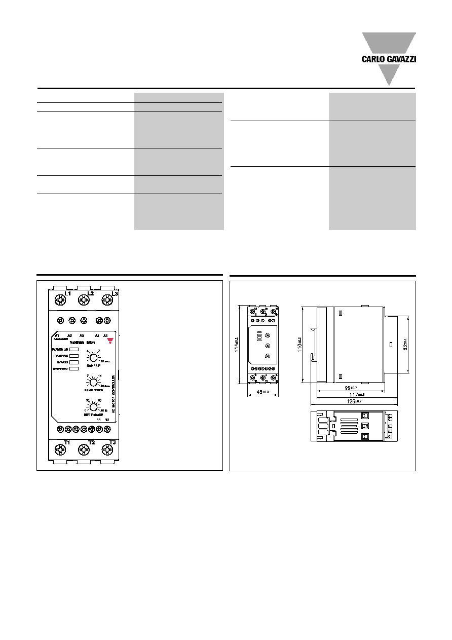
Dimensions
1
2
4
6
3
5
8
0.5
0.5
All dimensions in mm
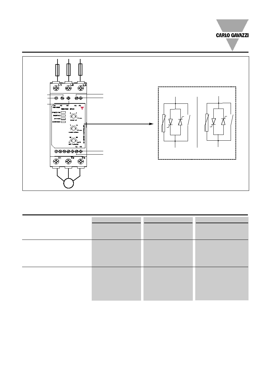
Terminal Diagram
L1, L2, L3: Mains supply
T1, T2, T3: Motor supply
A1, A2, A3: Control input
A4, A5:
External supply for
RSHRM ... models
11, 12:
End of ramp (NO)
for RSHR...V21
models
Standards
Approvals
UL, cUL listed (E172877)
Markings
CE
EMC
(Electromagnetic compatability)
accord. to EN/IEC 60947-4-2
Wire conducted emission
Class A
Radiated emission
Class A
ESD Immunity
(EN 61000-4-2)
4kV contact, PC2
8kV air discharge, PC1
Radiated RF immunity
(EN 61000-4-3)
10V/m, PC1 (80-1000MHz)
Voltage dips and interruptions
(EN 61000-4-11)
0% Ue & Uc, 20ms, PC2
40% Ue & Uc, 200ms, PC2
70% Ue & Uc, 5000ms, PC2
Fast transient immunity
(EN 61000-4-4)
Output
2kV, PC1 (4kV, PC2)
Input
2kV, PC1
Surge immunity (EN 61000-4-5)
Output: line to line
1kV, PC1
line to ground
2kV, PC1
Input: line to line
1kV, PC2 (500V, PC1)
line to ground
2kV, PC2 (500V, PC1)
Conducted RF immunity
(EN 61000-4-6)
140dBuV, PC1 (0.15-80MHz)
Note: EMC testing was performed with the RSHR connected to representative motor loads of 1.1/ 4.0kW. The EMC performance of the controller would eventu-
ally have to be evaluated with the controller connected and fitted as part of the complete system in the end application.
Specifications are subject to change (03.08.2006)
5
RSHR MIDI
Short circuit Protection (according to EN/IEC 60947-4-2 and UL 508)
RSHR..06BV21
RSHR..12BV21
RSHR..18BV21
Type of coordination: 1
UL rated short circuit current
5kA when protected
10kA when protected
10kA when protected
by RK5 fuses*
by RK5 fuses*
by RK5 fuses
RK5 fuse
220VACrms TRS12R 12A
TRS20R 20A
TRS30R 30A
400VACrms TRS12R 12A
TRS30R 30A
TRS35R 35A
480VACrms TRS12R 12A
TRS20R 20A
TRS30R 30A
600VACrms TRS12R 12A
TRS20R 20A
TRS35R 35A
Type of coordination: 2
Rated short circuit current
10kA when protected
10kA when protected
10kA when protected
by semiconductor fuses
by semiconductor fuses
by semiconductor fuses
Semiconductor fuse
Ferraz Shawmut
Ferraz Shawmut
Ferraz Shawmut
25A, Class URC
40A, Class URC
40A, Class URC
Art. No. 6.9 CP gRC 14.51 25 Art. No. 6.9 CP gRC 14.51 40
Art. No. 6.9 CP gRC 14.51 40
Connection Diagram
1
2
4
6
3
5
8
0.5
0.5
M
3 ~
L1
L2
L3
24VAC/VDC*
Max. 250VAC/30VDC, 3A
(used only on RSHR...BV21 models)
24-110VAC/DC
0V
110-480VAC
(used in RSHRM models only)
* For the 24VDC external supply, CG power supply model SPD24051 can be used
* 10kA for RSHR60 models
T1
T2
T3
L1
L2
L3
6
Specifications are subject to change (03.08.2006)
RSHR MIDI
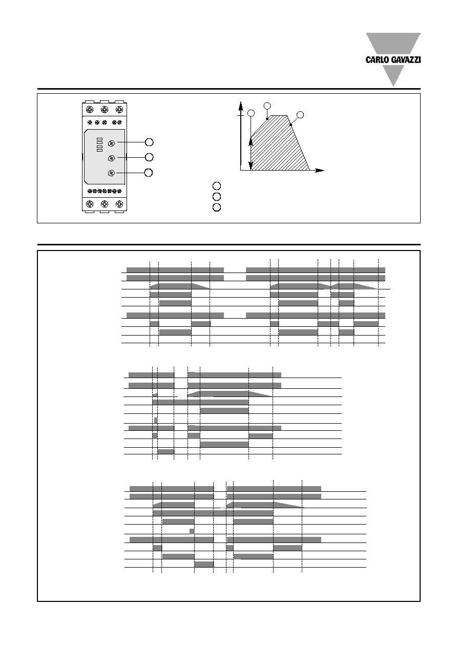
Operation Diagram
3
1
2
100%
Motor voltage
Time
1
Ramp-up time 0.5 to 10 s. Time from zero load voltage to full load voltage.
2
Ramp-down time 0.5 to 20 s. Time from full load voltage to zero load voltage.
3
Initial torque 0 to 85% voltage at the start of the ramp-up function.
1
2
3
Operation Diagrams for RSHR MIDI
Note: for proper operation of RSHRM models always remove mains supply voltage before switching off external power supply.
Diagram 1: Normal Operation
Mains supply L1, L2, L3
External supply A4, A5*
Motor supply T1, T2, T3
Control Input Uc
End of ramp **
Auxiliary output relay
Power ON LED
Ramping LED
Bypass LED
Overheat alarm LED**
Mains supply L1, L2, L3
External supply A4, A5*
Motor supply T1, T2, T3
Control Input Uc
End of ramp **
Auxiliary output relay
Device over-temperature
Power ON LED
Ramping LED
Bypass LED
Overheat alarm LED**
Mains supply L1, L2, L3
External supply A4, A5*
Motor supply T1, T2, T3
Control Input Uc
End of ramp **
Auxiliary output relay
Device over-temperature
Power ON LED
Ramping LED
Bypass LED
Overheat alarm LED**
Diagram 2: Over-temperature alarm during ramping mode **
Diagram 3: Over-temperature alarm during bypass mode **
* Applicable to RSHRM models only
** Applicable to RSHR ...BV21 models only
Specifications are subject to change (03.08.2006)
7
RSHR MIDI
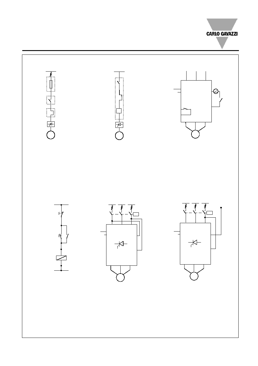
IEC
Wiring Diagram
RSHP
M
3~
K
Fuse
Contactor
Overload
I>
RSHP
M
3~
Motor
protection
relay
A1
A2
L1
L2
L3
U/T1 V/T2 W/T3
P1
P2
Motor
PTC
input
11
21
22
Alarm
Bypass ON
Common
K
M
3 ~
~
---
K
K
S1(ON)
S2(OFF)
A1
A2
A1
A2
L1
L2
L3
U/T1 V/T2 W/T3
K
M
3 ~
Fig. 1a
Fig. 2a
Fig. 3a
Fig. 4a
Fig. 5a
RSHR
RSHR
A2
or
A3
A3
A2 or A3
Ext. A4
Supply A5
A1
A3
L1
L2
L3
U/T1 V/T2 W/T3
K
M
3 ~
A2
N
Fig. 6a
A3
Ext. A4
Supply A5
Ext. A4
Supply A5
12
11
End of Ramp
Motor
protection
Relay
Fuse
Contactor
Overload
8
Specifications are subject to change (03.08.2006)
NEMA
Wiring Diagram (cont.)
RSHP
M
3~
K
Fuse
Contactor
Overload
RSHP
M
3~
Motor
protection
relay
A1
A2
Stop
Start
K
K
A1
A2
1
L1
3
L2
5
L3
2
T1
4
T2
6
T3
M
3 ~
K
K
K
Fig. 1b
Fig. 2b
Fig. 4b
Fig. 5b
RSHR
RSHR
A2
or
A3
A3
Ext. A4
Supply A5
A1
A3
A2
1
L1
3
L2
5
L3
2
T1
4
T2
6
T3
M
3 ~
K
K
K
N
Fig. 6b
Ext. A4
Supply A5
RSHR MIDI
The motor controller provides
by-passing of the semicon-
ductors during running opera-
tion. Therefore the semicon-
ductors can only be damaged
by short-circuit currents dur-
ing ramp-up and ramp-down.
Please note that the motor
controller does not isolate the
motor from the mains.
Figure 1: Protection of the
device when using fuses.
Protection with semiconduc-
tor fuses is intended to pro-
tect the motor feeder and
motor controller from damage
due to short-circuit.
Figure 2: Protection using a
thermal-magnetic motor
protection relay.
The motor feeder is protected
but damage to the motor
controller is possible. When
motor failure occurs, if part of
the motor winding limits the
fault current and the motor
feeder is protected, this type
of protection can be consid-
ered acceptable.
Figure 3: Secondary con-
ductors.
3.1: Control using a 2-position
switch.
When K is closed, the control
input is supplied to A1, A2 or
A3 and soft starting of the
motor is performed. When K
is opened, soft stopping is
performed.
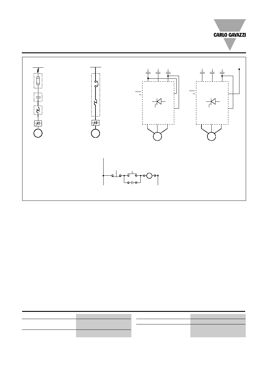
3.2: Auxiliary Relay
(For RSHR...BV21 models)
The End of Ramp relay 11, 12
(NO) can be used in series
with the supply to the coil of
an external bypass contactor.
Figure 4: Control using ON
and OFF push buttons
Pushing S1 soft starts the
RSHR. Pushing S2 soft stops
the RSHR. K is an auxiliary con-
tact of the mains contactor.
Figure 5: Control using 2
phases
Connecting input A1, A3 to
two of the incomming lines
will soft start the motor when
K is operated. When K is
switched off, the motor will
stop (no soft stop). This con-
figuration does not apply to
the RSHR60.... versions.
Figure 6: Control when
using operational voltage
greater than 480V
Connecting A1 to Neutral and
A3 to one of the incoming
phases (or vice-versa) will soft
start the motor when K is
closed. When K is opened, the
motor will stop (no soft stop).
For further details refer to Carlo Gavazzi SPD series datasheet
Accessories - External Power Supply 24VDC - SPD 24051
Rated input voltage
100-240
Voltage range
AC
90 - 265VAC
DC
120 - 370VDC
Frequency range
47 - 63Hz
Voltage trim range
21.6 - 28.8VDC
Output voltage accuracy
± 1%
Output current
0.21A