
Specifications are subject to change without notice (30.09.2005)
1
Rated operational
Control
Rated operational current
voltage
voltage
3 x 25 A
3 x 40 A
3 x 55 A
3 x 75 A
400 VACrms
5 VDC
RZ3A40LD25
RZ3A40LD40
RZ3A40LD55
RZ3A40LD75
4-32 VDC
RZ3A40D25
RZ3A40D40
RZ3A40D55
RZ3A40D75
24-275 VAC/24-50 VDC
RZ3A40A25
RZ3A40A40
RZ3A40A55
RZ3A40A75
600 VACrms
5 VDC
RZ3A60LD25
RZ3A60LD40
RZ3A60LD55
RZ3A60LD75
4-32 VDC
RZ3A60D25
RZ3A60D40
RZ3A60D55
RZ3A60D75
24-275 VAC/24-50 VDC
RZ3A60A25
RZ3A60A40
RZ3A60A55
RZ3A60A75
Notes
Over-temperature protection and alarm output: add suffix P to include over-temperature protection and alarm output.
Example: RZ3A60D75P. Not available with "LD" type control.
Switching
Rated operational
Rated operational
Control
Option
mode
voltage
current
voltage
A: Zero Switching
40: 400 VACrms
25: 3 x 25 AACrms
LD: 5 VDC
P: Over-
60: 600 VACrms
40: 3 x 40 AACrms
D: 4-32 VDC
temperature
55: 3 x 55 AACrms
A: 24-275 VAC/24-50 VDC
protection and
75: 3 x 75 AACrms
alarm output
(available only for A and D input)
Selection Guide
Solid State Relay
Number of poles
Switching mode
Rated opertional voltage
Control voltage
Rated opertional current
Options
A Solid State Relay family
designed to switch various
loads such as heating ele-
ments, motors and transform-
ers. The relay is capable of
switching high voltages up to
600 VACrms.
For higher reliability and load
cycle capability three semi-
conductor power units are sol-
dered directly on to the direct
copper bonded (DCB) sub-
strate.
AC- or DC-controlled versions
are available. Built-in LED sta-
tus indication for applied con-
trol voltage and over-tempera-
ture alarm (optional). A version
that can be controlled with 5
VDC @ 15 mA (max) is also
available (LD).
The series covers a range of
load currents up to 75 AACrms.
Solid State Relays
Industrial, 3-Phase ZS
Type RZ3A
� 3-phase Solid State Relay
� Zero switching
� Rated operational current: 3 x 25, 40, 55 or 75 A
� Rated operational voltage: Up to 600 VAC
� Control voltage 5 VDC, 4-32 VDC or 24-275 VAC
� Integral snubber network
� Over-temperature protection option with alarm output
� IP 10 back-of-hand protection
� LED indication of control input and over-temperature
alarm status
Ordering Key
Product Description
Type Selection
RZ 3 A 60 D 75 P
Rated insulation voltage
Input to output
4000 VACrms
Output to case
4000 VACrms
Operating temperature
-30� to +80�C (-22� to +158� F)
Storage temperature
-40� to +100�C (-40� to + 212� F)
Junction temperature
+125�C (+ 257�F)
Thermal Specifications
Insulation

2
Specifications are subject to change without notice (30.09.2005)
RZ3A..25..
RZ3A..40..
RZ3A..55..
RZ3A..75..
Rated operational current
AC51 @ Ta=25�C
25 Arms
40 Arms
55 Arms
75 Arms
AC53a @ Ta=25�C
5 Arms
8 Arms
15 Arms
20 Arms
Minimum operational current
150 mArms
150 mArms
150 mArms
150 mArms
Rep. overload current t=1 s
37 Arms
60 Arms
< 125 Arms
< 150 Arms
Non-rep. surge current t = 10 ms
300 A
p
390 A
p
580 A
p
1150 A
p
Off-state leakage current
< 3 mArms
< 3 mArms
< 3 mArms
< 3 mArms
I
2
t for fusing t = 1-10 ms
450 A
2
s
760A
2
s
1680 A
2
s
6600 A
2
s
Critical dI/dt @ 50 Hz
50 A/�s
50 A/�s
50 A/�s
50 A/�s
On-state voltage drop
1.6 Vrms
1.6 Vrms
1.6 Vrms
1.6 Vrms
Critical dV/dt off-state
500 V/�s
500 V/�s
500 V/�s
500 V/�s
RZ3A40..
RZ3A60..
Operational voltage range
24-440 VAC
42-660 VAC
Non-rep. peak voltage
850 V
p
1200 V
p
Operational frequency range
45 to 65 Hz
45 to 65 Hz
Overvoltage category
III
III
Pollution degree
3
3
Approvals
UL, cUL, CSA
UL, cUL,CSA
CE-marking
Yes
Yes
General Specifications
RZ3A
Input Specifications
RZ3A..LD..
RZ3A..D..
RZ3A..A..
Control voltage range
5 VDC
4-32 VDC
24-275 VAC/24-50 VDC
Pick-up voltage
4.5 VDC
3.8 VDC
18 VAC/20 VDC
Drop-out voltage
1.2 VDC
1.2 VDC
9 VAC/DC
Input current
15 mA
23 mA
15 mA
Response time pick-up
Power output = 50 Hz
10 ms
10 ms
20 ms
Response time drop-out
Power output = 50 Hz
10 ms
10 ms
30 ms
All data specified at Ta=25�C
Output Specifications
Over-temperature Protection (Option: ...P)
*After over-temperature condition is removed, SSR can be reset by switching OFF the control input for more than 20 ms and switching back ON: this will
*
switch ON the SSR output
SSR Input*
Green LED
Red LED
SSR Output
Alarm status
Over-temperature
sensing
Closed
Open
Over-temperature
detection
20ms
Over-temperature protection is ON
SSR output disabled
Specifications are subject to change without notice (30.09.2005)
3
Collector - emitter voltage
35 Vdc
Emitter - collector voltage
6 Vdc
Collector current
50 mA
Delay time on reset
20 ms
Alarm Output Specifications
RZ3A
75.0
0.27
0.22
0.17
0.12
0.07
0.02
--
201
70.0
0.32
0.27
0.21
0.16
0.10
0.05
--
184
65.0
0.38
0.32
0.26
0.20
0.14
0.08
0.02 167
60.0
0.44
0.38
0.31
0.25
0.18
0.11
0.05 151
55.0
0.52
0.45
0.38
0.30
0.23
0.16
0.08 136
50.0
0.62
0.54
0.45
0.37
0.29
0.21
0.12 121
45.0
0.74
0.64
0.55
0.46
0.36
0.27
0.17 106
40.0
0.87
0.76
0.65
0.54
0.43
0.32
0.22
92
35.0
1.01
0.89
0.76
0.63
0.51
0.38
0.25
79
30.0
1.21
1.06
0.91
0.76
0.60
0.45
0.30
66
25.0
1.49
1.30
1.11
0.93
0.74
0.56
0.37
54
20.0
1.90
1.67
1.43
1.19
0.95
0.71
0.48
42
15.0
2.60
2.28
1.95
1.63
1.30
0.98
0.65
31
10.0
4.01
3.51
3.01
2.51
2.01
1.50
1.00
20
5.0
8.24
7.21
6.18
5.15
4.12
3.09
2.06
10
20
30
40
50
60
70
80
55.0
0.29
0.23
0.17
0.11
0.05
--
--
164
50.0
0.36
0.29
0.22
0.16
0.09
0.02
--
148
45.0
0.44
0.36
0.29
0.21
0.14
0.06
--
133
40.0
0.54
0.46
0.37
0.29
0.20
0.12
0.03 118
35.0
0.67
0.58
0.48
0.38
0.28
0.19
0.09 103
30.0
0.85
0.74
0.62
0.51
0.39
0.28
0.16
87
25.0
1.10
0.96
0.82
0.68
0.55
0.41
0.27
73
20.0
1.38
1.21
1.04
0.87
0.69
0.52
0.35
58
15.0
1.85
1.62
1.39
1.16
0.93
0.70
0.46
43
10.0
2.80
2.45
2.10
1.75
1.40
1.05
0.70
29
5.0
5.62
4.92
4.21
3.51
2.81
2.11
1.40
14
2.5
11.26
9.85
8.45
7.04
5.63
4.22
2.82
7
20
30
40
50
60
70
80
25.0
0.44
0.34
0.23
0.12
0.01
--
--
92
22.5
0.62
0.49
0.37
0.24
0.12
--
--
80
20.0
0.84
0.69
0.54
0.40
0.25
0.10
--
68
17.5
1.12
0.95
0.78
0.60
0.43
0.25
0.08
58
15.0
1.51
1.30
1.09
0.88
0.67
0.46
0.25
47
12.5
2.06
1.80
1.54
1.27
1.01
0.75
0.48
38
10.0
2.75
2.40
2.06
1.72
1.37
1.03
0.69
29
7.5
3.83
3.35
2.87
2.39
1.91
1.43
0.96
21
5.0
6.01
5.26
4.51
3.76
3.01
2.25
1.50
13
2.5
12.62 11.04 9.46
7.89
6.31
4.73
3.15
6
20
30
40
50
60
70
80
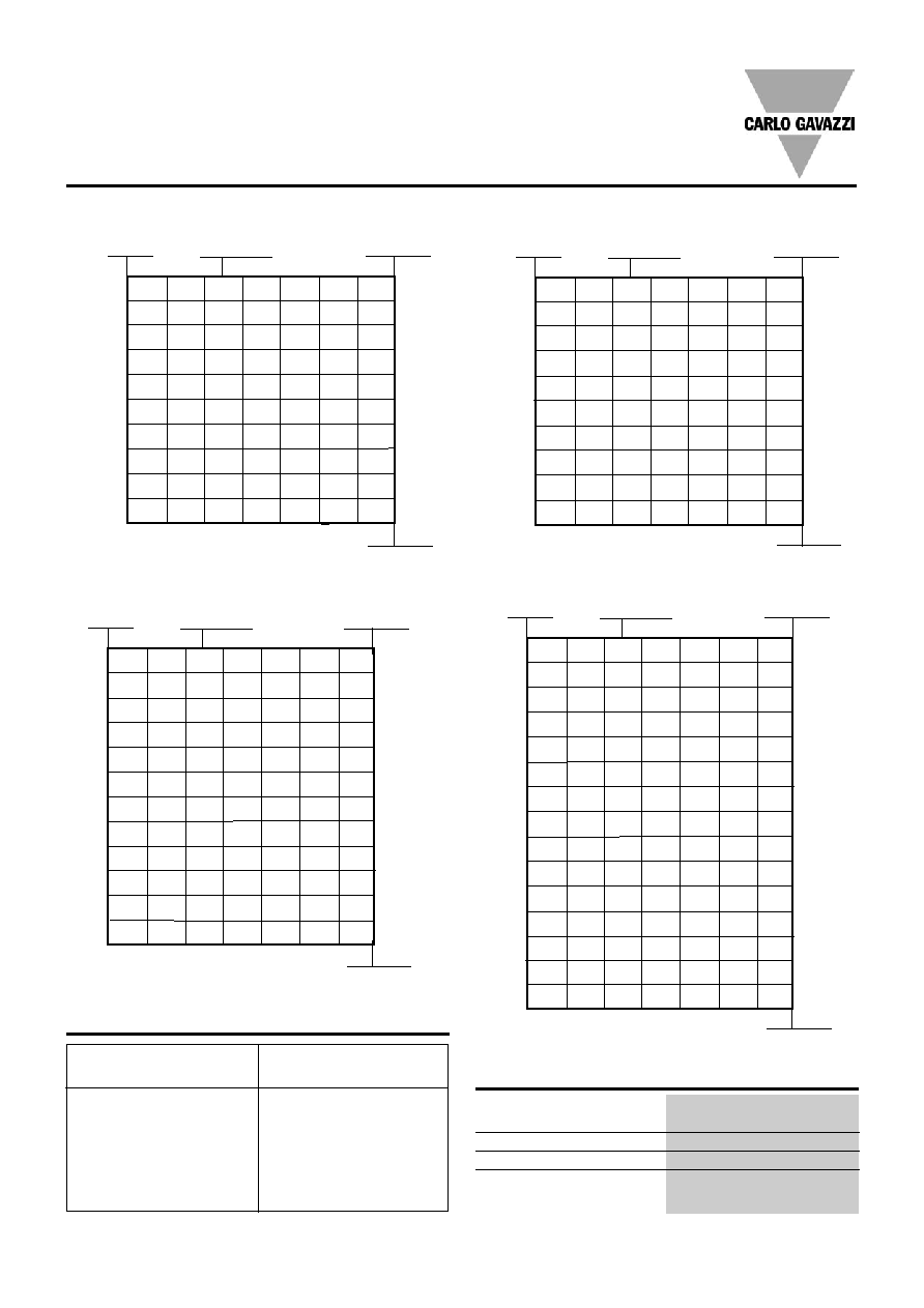
Heatsink Dimensions
(load current versus ambient temperature)
RZ3..25
Power
dissipation [W]
Load
current [A]
Thermal
resistance [K/W]
Ambient temp [�C]
T
A
40.0
0.54
0.44
0.34
0.24
0.14
0.04
--
101
36.0
0.66
0.55
0.44
0.33
0.22
0.11
--
91
32.0
0.81
0.68
0.56
0.43
0.31
0.18
0.06
80
28.0
1.00
0.86
0.72
0.57
0.43
0.29
0.14
70
24.0
1.26
1.09
0.93
0.76
0.59
0.42
0.25
60
20.0
1.62
1.42
1.21
1.01
0.81
0.61
0.41
49
16.0
2.03
1.78
1.52
1.27
1.02
0.76
0.64
39
12.0
2.72
2.38
2.04
1.70
1.36
1.02
1.03
29
8.0
4.11
3.59
3.08
2.57
2.05
1.54
1.81
19
4.0
8.26
7.22
6.19
5.16
4.13
3.10
4.14
10
20
30
40
50
60
70
80
RZ3 ..40
Power
dissipation [W]
Load
current [A]
Thermal
resistance [K/W]
Ambient temp [�C]
T
A
RZ3 ..55
Power
dissipation [W]
Load
current [A]
Thermal
resistance [K/W]
Ambient temp [�C]
T
A
RZ3 ..75
Power
dissipation [W]
Load
current [A]
Thermal
resistance [K/W]
Ambient temp [�C]
T
A
Carlo Gavazzi Heatsink
(see Accessories)
No heatsink required
RHS 300 Assy or backplate
RHS 112A Assy
RHS 301 Assy
RHS 112A F Assy
RHS 301 F Assy
Consult your distributor
Thermal resistance
R
th s-a
> 8.0
K/W
5.0
K/W
1.1
K/W
0.8 K/W
0.4
K/W
0.25 K/W
< 0.25 K/W
Heatsink Selection

4
Specifications are subject to change without notice (30.09.2005)
RZ3A
Connection Diagrams
Alarm Output Connection
VCC
Logic Input
B1
B2
RZ3A..
Alarm Output
VCC
Logic Input
Housing Specifications
Weight
Approx. 380 g
Material
Noryl
Base plate
25, 40, 55A
Aluminum, nickel-plated
75A
Copper, nickel-plated
Potting compound
Polyurethane
Relay
Mounting screws
M5
Mounting torque
1.5 Nm
Control terminal
Mounting screws
M4
Mounting torque
0.5 Nm
Wire size
Max.
2 x 2.5 mm
2
(AWG14)
Min.
2 x 1 mm
2
Power terminal
Mounting screws
M5
Mounting torque
2.5 Nm
Wire size
Max.
2 x 6 mm
2
(AWG8)
Min.
2 x 1 mm
2
Heatsink
Compound
47.6
73.5
41
92
103
5.3
12
B1
B2
L1
L2
L3
T1
T2
T3
A1
A2
6xM5
4xM4
Relay On LED
Over-temperature Alarm Trip LED (suffix "P" option)
All dimensions in mm
B1
B2
Logic
Input
A1
A2
B1
B2
A1
A2
B1
B2
A1
A2
Regulation
ZC
ZC
ZC
Over Temp
Circuit
A1 (~) (+)
A2 (~) (-)
B1 (+)
B2 (-)
Control
Input
AC/DC
Alarm
Output
T1
T2
T3
L1
L2
L3
Output A
Output B
Output C
Terminal Wiring
Common Alarm Wiring
Forward voltage
35 VDC
Reverse voltage
6 VDC
Through current
50mA
Alarm reset: interrupt control
input for more than 20ms
Active Low
Active High
Dimensions