 | –≠–ª–µ–∫—Ç—Ä–æ–Ω–Ω—ã–π –∫–æ–º–ø–æ–Ω–µ–Ω—Ç: UDM35 | –°–∫–∞—á–∞—Ç—å:  PDF PDF  ZIP ZIP |
Specifications are subject to change without notice UDM35DS 040706
1
∑ Multi-input modular instrument 3 1/2 dgt LED
∑ 0.1% RDG basic accuracy
∑ TRMS AC current and voltage measurements
∑ AC/DC current measurements: selectable full scales
(200µA to 5A)
∑ AC/DC voltage measurements: selectable full scales
(200mV to 500V)
∑ ∞C or ∞F temperature measurements
(Pt100-250-500-1000, Ni100, TC J-K-S-T-E)
∑ Resistance measurements: selectable full scales
(20
to 20k)
∑ Up to 4 independent alarm set-points (optional)
∑ 20mA/10VDC analog output (optional)
∑ Serial port RS485 or RS232 (optional)
∑ MODBUS, JBUS communication protocol
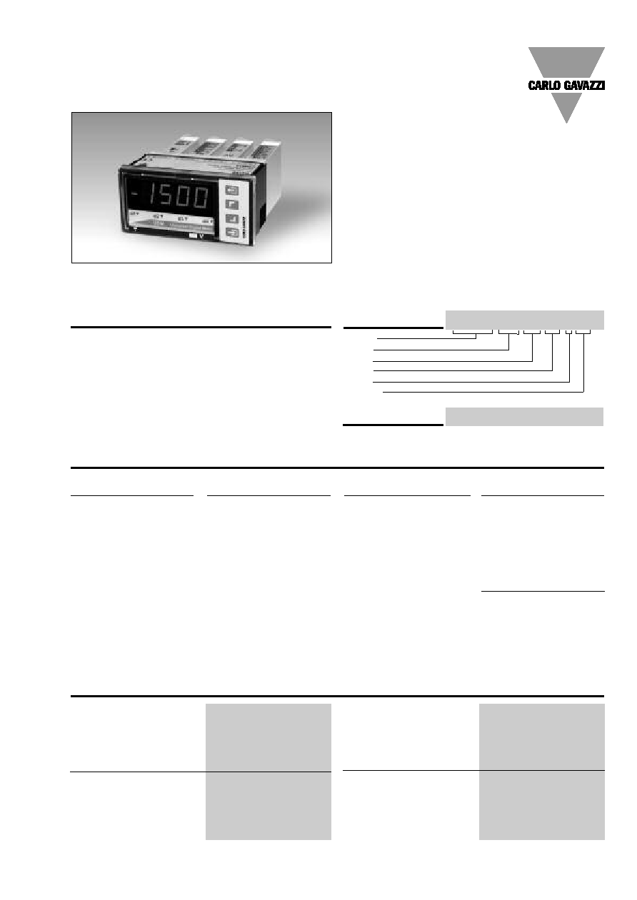
Product Description
µp-based digital panel
meter, 3 1/2 dgt LED indica-
tor, for current, voltage, tem-
perature
and resistance
measurements. Measuring
ranges and functions easily
programmable from the key-
pad or from the PC by
means of optional UdmSoft
software. UDM
35
includes
storage min-max functions
and double level protection
password. Housing for
panel mounting with front
protection degree: IP67,
NEMA4x.
Type UDM35
Type Selection
Slot A (measuring inputs)
LSX:
signal inputs:
0.2-2-20mA DC/AC;
0.2-2-20V DC/AC
LSE/
LSF:
signal inputs + AUX:
0.2-2-20mA DC/AC;
0.2-2-20V DC/AC
HSX:
signal inputs:
0.2-2-5A DC/AC;
20-200-500V DC/AC
TRX:
signal inputs: TC tem-
perature probes (J-K-S-
T-E, Pt100-250-500-
1000) and resistance
(0.02-0.2-2-20k
)
Slot B (communication)
XX:
None
SX:
Serial port RS485
SY:
Serial port RS232
AV (*): Single analogue output,
0 to 20mA DC and
0 to 10V DC
Slot D (power supply)
H:
90 to 260V AC/DC
L:
18 to 60V AC/DC
Options
XX:
None
TX:
Tropicalization
Model
Slot A
Slot B
Slot C
Slot D
Options
How to order
UDM35 XXX XX XX X XX
Analogue inputs
Channels and variable
BQ LSX module
1, mA and V DC/AC
BQ LSE/BQ LSF module
1, mA and V DC/AC + AUX
BQ HSX module
1, A and V DC/AC
BQ TRX module
1, temperature
BQ TRX module
1, resistance
Digital inputs
Incl. in the measuring module
Number of inputs
1 (voltage-free)
Use
key-pad lock
Display hold
Reset of latch alarms
Contact reading signal
BQ xxx: <0.1mA, <3,5V DC
BQ LSE/BQ LSF: <2.5mA,
<14V DC
Close contact resistance
Max 1k
Open contact resistance
Min 500k
Insulation
Non-insulated
Accuracy (display, RS485)
See table "Measuring
accuracy", temperature drifts
and minimum-maximum
indications"
Input Specifications
∑ Front protection degree: IP67, NEMA4x
How to order
UdmSoft-kit
UdmSoft-kit: software plus "UCOM1" communication cable for
programming UDM
35
by means of PC.
Modular Indicator and Controller
Digital Panel Meters
Slot C (communication and alarm)
XX:
None
R1:
single relay output,
(AC1-8AAC, 250VAC)
R2:
Dual relay output,
(AC1-8AAC, 250VAC)
R4:
Dual relay output (AC1-
8AAC, 250VAC) + dual
open collector output
(NPN, 100mA)
R5:
4 relay outputs
(AC1-5AAC, 250VAC)
AV(*): Single analogue output,
0 to 20mA DC and
0 to 10V DC
(*):
The two analogue
outputs cannot be
used at the same
time. It is possible to
plug in only one
module by instru-
ment.

2
Specifications are subject to change without notice UDM35DS 040706
UDM35
Module
Inputs
Type
Accuracy
Temp. drift
Min. indicat. ( )
Max. indicat. ( )
BQ LSX/
BQ LSE/
BQ LSF
-200µA to +200µA
-2mA to +2mA
-20mA to +20mA
-200mV to +200mV
-2V to +2V
-20V to +20V
DC/AC
DC: ±(0.1%RDG+3DGT)
0% to 25% FS;
±(0.1%RDG+2DGT)
25% to 110% FS.
TRMS (45 to 65Hz)*:
±(0.3%RDG+3DGT)
0% to 25% FS;
±(0.3%RDG+2DGT)
25% to 110% FS.
±150 ppm/∞C
- 199.9
- 1.999
- 19.99
- 199.9
- 1.999
- 19.99
+ 199.9
+ 1.999
+ 19.99
+ 199.9
+ 1.999
+ 19.99
BQ HSX
-200mA to +200mA
-2A to +2A
-5A to +5A
-20V to +20V
-200V to +200V
-500V to +500V
DC/AC
DC: ±(0.1%RDG+3DGT)
0% to 25% FS;
±(0.1%RDG+2DGT)
25% to 110% FS.
TRMS (45 to 65Hz)*:
±(0.3%RDG+3DGT)
0% to 25% FS;
±(0.3%RDG+2DGT)
25% to 110% FS.
±150 ppm/∞C
- 199.9
- 1.999
- 5.00
- 19.99
- 199.9
- 500
+ 199.9
+ 1.999
+ 5.00
+ 19.99
+ 199.9
+ 500
BQ TRX
thermo-
couple
-50∞C to +760∞C
-58 ∞F to +1400 ∞F
-200∞C to +1260∞C
-328 ∞F to +2000∞F
-200∞C to +1000∞C
-328∞F to +1832∞F
-50∞C to +1750∞C
-58∞F to +2000∞F
-200∞C to +400∞C
-328∞F to +752∞F
J
J
K
K
E
E
S
S
T
T
±(0.2%RDG+1DGT)
±(0.2%RDG+2DGT)
±(0.2%RDG+2DGT)
±(0.2%RDG+4DGT)
±(0.2%RDG+2DGT)
±(0.2%RDG+4DGT)
±(0.2%RDG+2DGT)
±(0.2%RDG+4DGT)
±(0.2%RDG+2DGT)
±(0.2%RDG+4DGT)
±150 ppm/∞C
- 50∞C
- 58∞F
- 200∞C
- 328∞F
- 200∞C
- 328∞F
- 50∞C
- 58∞F
- 200∞C
- 328∞F
+ 760∞C
+ 1400∞F
+ 1260∞C
+ 1999∞F
+ 1000∞C
+ 1832∞F
+ 1750∞C
+ 1999∞F
+ 400∞C
+ 752∞F
Measurement accuracy, temperature drifts, max and min indications
All accuracies and min/max indications are referred to an ambient temperature range of 25∞C ±5∞C, relevant humidity
60% and scale ratio
(electrical/displayed scale) equal to 1. The conversion into ∞F is obtained acting on the electrical/displayed scale ratio.
Additional errors
Humidity
0.3% RDG, 60% to 90% R.H.
Input frequency
0.4% RDG, 62 to 440 Hz
Magnetic field
0.5% RDG @ 400 A/m
Temperature drift
See table "Measurement
accuracy, temperature drifts,
and max/min indications"
Sampling rate
500 samples/s @ 50 Hz
Display refresh time
200 msec @ 50Hz
Display
3 1/2 DGT,
7 segments
height 14.2 mm
Colour: red
Max and min indication
See table "Measurement
accuracy, temperature drifts
and max min indications"
Measurements
Current, voltage, tempera-
ture and resistance. For the
current and voltage mea-
surements: TRMS measure-
ment of distorted sine
waves.
Coupling type
Direct
Crest factor
3; A
Pmax
=1.7In; V
Pmax
=1.7Un
Input impedance
See table "input
impedances and overloads"
Frequency
40 to 440 Hz
Overload
See table "input
impedances and overloads"
Compensation
Only temperature
measurement module.
RTD
- For Pt 100-250-500-1000,
3-wire connection: up to 10
- For resistance measur. with
20
range: up to max 0.1
- For resistance measurements
with
200range: up to max 10
TC
Internal cold junction, within
the temperature range
from 0 to +50∞C.
Automatic compensation
or manual from 0 to 50∞C.
Input specifications (cont.)
*
<45Hz >65Hz= ±(0.5%RDG+3DGT) 0% to 25% FS; ±(0.5%RDG+2DGT) 25% to 110% FS.
( ) The min. indication for TRMS measurement (AC or DC) is 0; it is possible to modify the decimal point position.

Specifications are subject to change without notice UDM35DS 040706
3
UDM35
Module
Inputs
Type
Impedance
Overload (continuous)
Overloads (1s)
BQ LSX/
BQ LSE/
BQ LSF
-200µA to +200µA
-2mA to +2mA
-20mA to +20mA
-200mV to +200mV
-2V to +2V
-20V to +20V
DC/AC
DC/AC
DC/AC
DC/AC
DC/AC
DC/AC
2.2k
22
22
2.2k
200k
200k
5mA
50mA
50mA
10V
50V
50V
10mA
150mA
150mA
20V
100V
100V
BQ HSX
-200mA to +200mA
-2A to +2A
-5A to +5A
-20V to +20V
-200V to +200V
-500V to +500V
DC/AC
DC/AC
DC/AC
DC/AC
DC/AC
DC/AC
1
0.012
0.012
2M
2M
2M
0.8A
7.5A
7.5A
750V
750V
750V
1A
100A
100A
1000V
1000V
1000V
BQ TRX
Thermo-
couple
-50∞C to +760∞C
-58 ∞F to +1400 ∞F
-200∞C to +1260∞C
-328 ∞F to +2000∞F
-200∞C to +1000∞C
-328∞F to +1832∞F
-50∞C to +1750∞C
-58∞F to +2000∞F
-200∞C to +400∞C
-328∞F to +752∞F
J
J
K
K
E
E
S
S
T
T
I
LK
<0.5µA
Max 5V
Max 10V
BQ TRX
Thermo-
resistance
-200∞C to +850∞C
-328∞F to +1562∞F
-200.0∞C to +200.0∞C
-328∞F to +392∞F
-200.0∞C to+200.0∞C
-328∞F to +392∞F
-60∞C to +180∞C
-76∞F to +356∞F
Pt100
Pt100
Pt250/Pt100
Pt250/Pt100
Pt1000/Pt500
Pt1000/Pt500
Ni100
Ni100
800µA (*)
800µA (*)
90µA (*)
90µA (*)
800µA (*)
800µA (*)
800µA (*)
800µA (*)
Max 5V
Max 10V
BQ TRX
Resistance
0 to 20
0 to 200
0 to 2000
0 to 20.00k
800µA (*)
90µA (*)
800µA (*)
90µA (*)
Max 5V
Max 10V
Input impedances and overloads
Module
Inputs
Type
Accuracy
Temp. Drift
Min. Indication
Max. Indication
BQ TRX
Ther-
moresis-
tance
-200∞C to +850∞C
-328∞F to +1562∞F
-200.0∞C to +200.0∞C
-328∞F to +392∞F
-200.0∞C to +200.0∞C
-328∞F to +392∞F
-200.0∞C to +200.0∞C
-328∞F to+392∞F
-200.0∞C to +200.0∞C
-328∞F to +392∞F
-60∞C to +180∞C
-76∞F to +356∞F
Pt100
Pt100
Pt100
Pt100
Pt250
Pt250
Pt500
Pt500
Pt1000
Pt1000
Ni100
Ni100
±(0.2%RDG + 2DGT)
±(0.2%RDG + 4DGT)
±(0.5%RDG + 5DGT)
±(0.5%RDG + 5DGT)
±(0.5%RDG + 5DGT)
±(0.5%RDG + 5DGT)
±(0.5%RDG + 5DGT)
±(0.5%RDG + 5DGT)
±(0.5%RDG + 5DGT)
±(0.5%RDG + 5DGT)
±(0.5%RDG + 1DGT)
±(0.5%RDG + 2DGT)
±150 ppm/∞C
- 200
- 328
-199.9
-199.9
-199.9
-199.9
-199.9
-199.9
-199.9
-199.9
- 60
- 76
+ 850
+ 1562
+199.9
+199.9
+199.9
+199.9
+199.9
+199.9
+199.9
+199.9
+ 180
+ 356
BQ TRX
Resis-
tance
0 to 20
0 to 200
0 to 2000
0 to 20.00k
±(0.2%RDG+2DGT)
25% to 110% FS
±(0.2%RDG+3DGT)
0% to 25% FS
±150 ppm/∞C
0
0
0
0
19.99 ( )
199.9 ( )
1999 ( )
19.99 ( )
(*) Maximum measuring current generated for resistance equal to 0.
Measurement accuracy, temp. drifts, min max indications (cont.)
All accuracies and min/max indications refer to an ambient temperature range of 25∞C ±5∞C, relevant humidity
60% and scale ratio (elec-
trical scale / displayed scale) equal to 1. The conversion into ∞F is obtained acting on the electrical scale / displayed scale .
( ) It is possible to modify the decimal point position.

4
Specifications are subject to change without notice UDM35DS 040706
UDM35
RS422/RS485 (on
request)
Module: BR SX
Serial output
Bidirectional (static and
dynamic variables).
LED
Display of data
reception/transmission
Connections
Multidrop, 2 or 4 wires
Distance
1000m
Terminalization
Directly on the module
by means of jumper
Addresses
1 to 255, selectable
by means of key-pad
Protocol
MODBUS RTU/JBUS
Data (bidirectional)
Dynamic (reading only)
Measurement, min value
max value
alarm status
Static (reading/writing)
All programming parameters,
min max reset
reset of latch alarm
Data format
8 data bit, no parity,
1 stop bit
Baud rate
selectable 4800, 9600,
19200 and 38400 bit/s
Insulation
By means of opto-couplers
4000 V
rms
output to
measuring inputs
4000 V
rms
output to
power supply input
RS232
(on request)
Module: BR SY
Serial output
Bidirectional (static and
dynamic variables)
Connections
3 wires,
Distance
max. 15m
Data format
1 start bit, 8 data bit,
no parity, 1 stop bit
Baud rate
Selectable 4800, 9600,
19200 and 38400 bit/s
Other features
Same as RS422/485
Alarm outputs
(on request)
Alarm type
Active alarm for out-of-range,
up alarm,
down alarm,
down alarm with
start-up deactivation,
up alarm with latch,
down alarm with latch
Alarm set-point
Adjustable from 0 to 100%
of displayed electric range
Hysteresis
0 to 100% of displayed range
On-time delay
0 to 255 s
Off-time delay
0 to 255 s
Output status
Selectable: normally
energized/de-energized
Min response time
500 ms, with filter excluded,
without alarm activation delay
Output channels
1 with BO R1 module (relay
output).
2, independent with module
BO R2 (2 relay outputs).
4, independent with BO R4
module (2 relay outputs +
2 open collector outputs).
BOR5 (4 relay outputs)
Relay output BO R1, R2, R4
Type SPDT
AC 1: 8A, 250VAC
DC 12: 5A, 24VDC
AC 15: 2,5A, 250VAC
DC 13: 2,5A, 24VDC
Relay output BOR5
Type SPDT (normally open)
AC 1: 5A, 250VAC
DC 12: 3A, 24VDC
AC 15: 1,5A, 250VAC
DC 13: 1,5A, 24VDC
Insulation
4000 V
RMS
output to
measuring input,
4000 V
RMS
output to
power supply input.
Open collector output
NPN transistor type
V
ON
1.2 VDC/ max. 100 mA
V
OFF
30 VDC max.
Insulation
By means of opto-couplers,
4000 V
RMS
output to
measuring input,
4000 V
RMS
output to power
supply input
Analogue output
(on request)
Module: BO AV
Range
0 to 20 mADC, 0 to 10 VDC
Scaling factor
Programmable within the
whole retransmission range;
it allows to manage the
retransmission of all values
from 0 to 20 mA / 0 to 10V
Accuracy
± 0.2% FS (@ 25∞C ± 5∞C)
Response time
10 ms
Temperature drift
± 200 ppm/∞C
Load: 20 mA output
700
10 V output
10 k
Insulation
By means of optocouplers
4000V
rms
output to measuring
input
4000V
rms
output to power
supply input
Notes:
The two outputs cannot be
used at the same time
Excitation output
(on request)
BQ LSE module
Voltage
13 VDC ±10%
max. 50 mA
Insulation
25V
rms
output to
measuring input
4000 V
rms
output to
power supply input
BQ LSF module
Voltage
25 VDC ±10%
max. 25 mA
Insulation
25V
rms
output to
measuring input
4000 V
rms
output to
power supply input
Output specifications
Specifications are subject to change without notice UDM35DS 040706
5
UDM35
Diagnostics
The display flashes when the
limits of the display range
are exceeded and the data
are updated up to 20%
of the rated display range.
Burn-out:
Only temperature inputs.
TC Opening
of
probe's
connection: EEE indication
RTD
Opening of probe's
connection: EEE indication
probe's short circuit:
-EEE indication.
Digital filter
Filter operating range
0 to 1999
Filtering coefficient
1 to 32
Display selection
3 1/2 DGT or 3 DGT plus
dummy zero
Scaling
Selection of min value
of the input range.
Selection of max value of
the input range.
Selection of decimal point
position.
Selection of min
displayable value.
Selection of max displayable
value.
UdmSoft
Software for programming
UDM35 by means of PC
(Windows 95, 98se, ME, XP)
by means of serial port
RS485 and relevant
connection cable.
The software is available in
English, Spanish, Italian,
German and French. See
also "Programming of
UDM35 by means of PC".
Min / Max storage
Automatic storage
(in the EEPROM) of the
minimum and maximum
measured value from the
previous memory reset
Password
Numeric code max 4 dgt
2 levels of data protection.
1st level
0 to 4999 completely protected.
2nd level
5000 to 9999 access to
programming is protected .
Alarm set-points are directly
programmable from the
measuring mode.
Measurement selection
Depending on the module:
measuring range and type of
probe (resistance, RTD
thermoresitance,
TC thermocouple) or
measuring type (TRMS or DC).
Integration time selection
Automatic or from 100.0 to
999.9 ms only in the current
and voltage measurement.
Scaling factor
Operating mode
Electrical scale compression,
displayed scale
compression/expansion
(max. 2 without filter, up to
10 with filter)
Electrical range
Programmable within the
whole measuring range
Decimal point position
Programmable within the
display range
Displayed range of the variable Programmable within
the display range
Software functions
Safety Standards
Safety
EN 61010-1, IEC 61010-1
Connections
Screw type
Wire section
Max 2.5mm
2
Housing
Dimensions
1/8 DIN, 48 x 96 x 105 mm
Material
PC-ABS,
self-extinguishing: UL 94 V-0
Protection degree
Front: IP67, NEMA4x
Connections: IP20
Weight
520 g approx (included all
modules and packing)
Approvals
CE, UR, CSA
Operating
0∞ to 50∞C (32∞ to 122∞F)
temperature
(R. H. < 90% non-condensing)
Storage
-10∞ to 60∞C (14∞ to 140∞F)
temperature
(R.H. < 90% non-condensing)
Insulation reference
300 V
RMS
to ground
voltage
(500V input)
Insulation
See table "Insulation between
inputs and outputs"
Dielectric strength
4000 V
RMS
for 1 minute
Rejection
NMRR
40 dB, 40 to 60 Hz
CMRR
100 dB, 40 to 60 Hz
EMC
EN61000-6-2, IEC61000-6-2
EN61000-6-3, IEC61000-6-3
General Specifications

6
Specifications are subject to change without notice UDM35DS 040706
UDM35
30
20
10
25
15
V
mA
0
10
20
30
40
50
60
5
AC/DC voltage
90 to 260V (standard)
18 to 60V (on request)
Energy consumption
30VA/12W (90 to 260V)
20VA/12W (18 to 60V)
Supply Specifications
Available modules
Only for TRMS Measurements
Instantaneous effective
voltage (TRMS)
Â
◊
=
n
i
V
n
V
1
2
1
1
)
(
1
Â
◊
=
n
i
A
n
A
1
2
1
1
)
(
1
Used calculation formulas
Instantaneous effective
current (TRMS)
Type
N. of
channels
Ordering
code
UDM35 main unit
BD 35
DC/AC input: 200µA, 2mA, 20mA,
200mA, 2V, 20V
1
BQ LSX
DC/AC input: 200µA, 2mA, 20mA,
200mA, 2V, 20V +excitation output
1
BQ LSE/
BQ LSF
DC/AC input: 200mA, 2A, 5A,
20V, 200V, 500V
1
BQ HSX
Input: 20,200,2k,20k
1
BQ TRX
TC: J-K-S-T-E, Pt100-250-500-1000
1
BQ TRX
Analogue output 0 to 20mA, 0 to 10VDC
1
BO AV
Relay output
1
BO R1
Relay output
2
BO R2
Outputs: 2 relays + 2 open collectors
4
BO R4
RS485 Serial Port
1
BR SX
Power supply 18 to 60V AC/DC
BP L
Power supply 90 to 260V AC/DC
BP H
Insulation between inputs and outputs
Meas.
inputs
Relay
output
Static
output
Analogue
output
Serial
Port
AUX
p.supply
90-260VAC/
DCp.supply
18-60VAC/
DC p.supply
Meas.
inputs
-
4kV
4kV
4kV
4kV
25V
4kV
4kV
Relay
Output
4kV
-
2kV
4kV
4kV
4kV
4kV
4kV
Static
Output
4kV
2kV
-
4kV
4kV
4kV
4kV
4kV
Analogue
Output
4kV
4kV
4kV
-
4kV
4kV
4kV
4kV
Serial
Port
4kV
4kV
4kV
4kV
-
4kV
4kV
4kV
AUX
p.supply
25V
4kV
4kV
4kV
4kV
-
4kV
4kV
90-260VAC/
DC p..supply
4kV
4kV
4kV
4kV
4kV
4kV
-
-
18-60V AC/
DC p. supply
4kV
4kV
4kV
4kV
4kV
4kV
-
-
Excitation output
Continuous
max. 30 s.
Possible module combinations
(*) Up to 1 module max.
Relay output
4
BO R5
RS232 Serial Port
1
BR SY
Basic Unit
Slot A Slot B Slot C Slot D
Measuring inputs:
LSX, LSE, LSF, HSX, TRX
RS485 Serial port: SX
RS232 Serial port: SY
Analogue output: AV (*)
Relay outputs and/or open
collector: R1, R2, R4, R5
Power supply: H, L
BQ LSE
BQ
LSF

Specifications are subject to change without notice UDM35DS 040706
7
UDM35
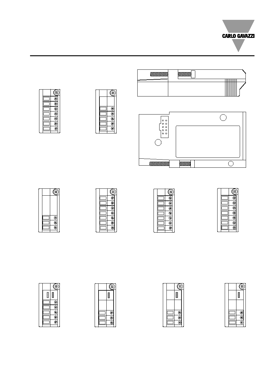
Wiring diagrams
Process signal wiring diagrams
Current measurements
4-wire connection to probe
Fig. 5
Current measurements
Voltage measurements
Fig. 1
Fig. 2
BQ LSE/LSF
BQ LSX/LSE/LSF
BQ LSX/LSE/LSF
Voltage measurements
4-wire connection to probe
Fig. 3
BQ LSE/LSF
Voltage measurements
3-wire connection to probe
Fig. 4
BQ LSE/LSF
Current measurements
3-wire connection to probe
Fig. 6
BQ LSE/LSF
-
+ Vdc
+
-
-
+ Vdc
+
-
+ Vdc
-
+
-
+ Vdc
+
P
r
o
b
e
P
r
o
b
e
P
r
o
b
e
P
r
o
b
e
Current measurements
2-wire connection to probe
Fig. 7
BQ LSE/LSF
+ Vdc
+
P
r
o
b
e
Voltage measurements
Fig. 9
BQ HSX
Current measurements
Fig. 8
BQ HSX
Wirings for high-level signals
-
~
+
~
-
~
+
~
-
~
+
~
-
~
+
~
P
r
o
b
e
p
o
w
e
r
s
u
p
p
l
y
P
r
o
b
e
S
i
g
n
a
l
o
u
t
p
u
t
P
r
o
b
e
p
o
w
e
r
s
u
p
p
l
y
P
r
o
b
e
S
i
g
n
a
l
o
u
t
p
u
t
P
r
o
b
e
p
o
w
e
r
s
u
p
p
l
y
P
r
o
b
e
S
i
g
n
a
l
o
u
t
p
u
t
P
r
o
b
e
p
o
w
e
r
s
u
p
p
l
y
P
r
o
b
e
S
i
g
n
a
l
o
u
t
p
u
t
P
r
o
b
e
p
o
w
e
r
s
u
p
p
l
y
P
r
o
b
e
S
i
g
n
a
l
o
u
t
p
u
t

8
Specifications are subject to change without notice UDM35DS 040706
UDM35
Wiring diagrams of optional modules
BO R1: 1 relay output
BO R2: 2 relay outputs
BO AV: analogue output
(10V, 20mA DC)
BP H: power supply
BP L: power supply
F1= 630mA T
250V 5x20mm
F1= 3.15A T
250V 5x20mm
Temp. measur. from thermoresistance
Temp. measur. from thermocouple
Resistance measurements
Fig. 10
Fig. 11
Fig. 12
Wiring diagrams for temperature measurements
BQ TRX
BQ TRX
BQ TRX
Wiring diagrams (cont.)
Wiring diagrams for power supply
BO R5: 4 relay outputs

Specifications are subject to change without notice UDM35DS 040706
9
UDM35
BO R4: dual relay output + dual open collector output: the load resistances (Rc) must be designed so that the close
contact current is lower than 100mA; the VDC voltage must be lower than or equal to 30VDC.
VDC: power supply output
Vo+: positive output (open collector transistor).
GND: ground collector (open collector transistor).
BR SX: RS485 4-wire connection: additional devices provided with RS485 port (indicated as RS1,2,3...N) are connected
in parallel. The termination of the serial port is carried out only on the last instrument of the network. The serial module is
provided with a jumper for the termination of the RS485 network as shown in the figure above.
Note: particular types of cables or plants may require an external termination. For the network connections use twisted
cable type AWG26.
RS1,2,3...N
NON terminalized network
Terminalized network
Programming UDM35 by means of PC
Wiring diagrams of optional modules (cont.)
Vdc
UDM35 is programmable by PC by means of the UdmSoft software (available on
request). The user can program all parameters of UDM35 that will be subse-
quently uploaded and set in the instrument by the RS485 network (BRSX).
Should UDM35 be without the RS485 serial module, all programming parameters
will be uploaded and set in the instrument by the RS232 auxiliary serial connec-
tion (1) located on the side of the measuring input module using the special con-
nection cable (2) available on request, as shown in the figures on the left. It is
also possible to program the instrument using the dot connector (1) by means of
the HyperTerminal Windows functions of a PC.
Note: the RS232 auxiliary port IS NOT insulated from the measuring inputs.
Ordering code of the cable (2): UCOM1
1
2
To UDM
To PC
1
m
3
2
1
SY
TX
RX
GND
T
X
R
X
LED
1
5
6
9
5
2
3
BO SY: RS232 direct
connection to PC by
means of COM port.
RS232 has no termi-
nalization.

10
Specifications are subject to change without notice UDM35DS 040706
UDM35
:
- to program values;
- to select functions;
- to scroll display pages.
: for special functions.
2. Display
Instantaneous measurements:
- 3 1/2 digit (max display 1999).
Alphanumeric indications by means of LED display for:
- Display of configuration parameters;
- The measured variable.
3. Alarm status LED
Display any alarm condition
4. Engineering unit
The instrument is supplied with a complete set of
self-sticking labels with the main engineering units.
Dimensions
Front panel description
1. Key-pad
The programming of the configuration parameters and the
display may be easily controlled by means of the 4 function
keys.
: to enter the programming phase and to confirm the
password.
Engineering Units
Panel depth: 8mm max.
105mm
11mm
48mm
96mm
92mm -0,3/+0,8
45mm -0,3/+0,6
2
1
4
3
Specifications are subject to change without notice UDM35DS 040706
11
UDM35
BP L
Power supply:
18 to 60V AC/DC
BO R4
Dual relay output +
Dual open collector
BO R2
Dual relay output
BO AV
Single analogue
output 10V, 20mA DC
BQ LSX, BQ LSE, BQ
LSF, BQ HSX, BQ TRX
Measuring inputs
Input modules
Serial port modules
BR SX
RS485 Serial port
BP H
Power supply:
60 to 260V AC/DC
Modules
BO R1
Single relay output
Output modules
Scale 1:1
Power supply modules
Output modules
BO R5
4 relay outputs
BR SY
RS232 Serial port