
INTERNAL BLOCK DIAGRAM
California Eastern Laboratories
UPD5702TU
NEC's 2.4 GHz
Si LD MOS POWER AMPLIFIER
FEATURES
∑ MEDIUM OUTPUT POWER:
P
OUT
= +21 dBm TYP @P
IN
= -2 dBm, f = 2.45 GHz
∑ ON CHIP OUTPUT POWER CONTROL FUNCTION
∑ SINGLE SUPPLY VOLTAGE:
V
DS
= 3.0 V TYP
∑ PACKAGED IN 8 PIN L2MM (2.0 X 2.2 X 0.5mm)
SUITABLE FOR HIGH- DENSITY SURFACE MOUNT
APPLICATIONS
∑ 1.9 GHZ Application Ex. PHS etc.
∑ 2.4 GHz application Ex. Bluetooth, Wireless LAN, etc.
∑ General purpose medium power AGC amplifier
PART NUMBER
UPD5702TU
SYMBOLS
PARAMETERS AND CONDITIONS
UNITS
MIN
TYP
MAX
I
DS
Circuit Current, P
IN
= -5 dBm, P
OUT
= +20.5 dBm
mA
150
V
GS
Gate Bias Voltage, P
IN
= -5 dBm, P
OUT
= +20.5 dBm
V
2.0
P
OUT
Output Power, P
IN
= -5 dBm
dBm
20.5
PAE
Power Added Efficiency, P
IN
= -5 dBm, P
OUT
= +20.5 dBm
%
27
Padj1
Adjacent Channel Power 1, P
IN
= -5 dBm, P
OUT
= +20.5 dBm
dBc
-61
Padj2
Adjacent Channel Power 2, P
IN
= -5 dBm, P
OUT
= +20.5 dBm
dBc
-76
IRL
Input Return Loss, P
IN
= -20 dBm
dB
10
ORL
Output Return Loss, P
IN
= -20 dBm
dB
10
ISOL
Isolation, P
IN
= -20 dBm
dB
45
OBW
Occupied Bandwidth, P
IN
= -5 dBm, P
OUT
= +20.5 dBm
dB
TBD
ELECTRICAL CHARACTERISTICS
(T
A
= 25∞C, V
DS
= 3.0 V, f = 1.9 GHz, unless otherwise specified)
DESCRIPTION
NEC's UPD5702TU is a silicon LD MOS IC designed for use as
a power amplifier up to 2.4 GHz application. This IC consists of
two stage amplifiers. The device is packaged in a low cost,
surface mount 8 pin L2MM (Leadless Mini Mold) plastic pack-
age. Ideally suited for high density surface mount designs.
NEC's stringent quality assurance and test procedures ensure
the highest reliability and performance.
1
2
3
4
5
6
7
8
Pin2
Pin2
GND
Pout1
Pout2
Pout2
GND
Pin1

SYMBOLS
PARAMETERS
UNITS MIN TYP MAX
V
DS
Supply Voltage 1
V
2.7
3.0
3.6
V
GS
Supply Voltage 2
V
0.0
0.2
≠
P
IN
Maximum Input Power
dBm
≠
+5
≠
I
D
Drain Current
mA
≠
165
≠
RECOMMENDED
OPERATING CONDITIONS
UPD5702TU
TYPICAL PERFORMANCE CURVES
(T
A
= 25∞C, f = 1.9 GHz, V
GS
= 2.0 V unless otherwise specified)
Circuit Current, I
DS
(mA)
Input Power, P
IN
(dBm)
OUTPUT POWER, GAIN AND
ADJACENT CHANNEL POWER
vs. INPUT POWER
Output Power, P
OUT
(dBm), Gain, G
A
(dB)
Input Power, P
IN
(dBm)
Adjacent Channel Power, P
adj
(dBc)
Pout
Gain
Padj (-900 KHz)
Padj (-600 KHz)
Padj (+600 KHz)
Padj (+900 KHz)
30
25
20
15
10
5
0
-15
-10
-5
0
5
10
-20
-30
-40
-50
-60
-70
-80
CIRCUIT CURRENT
vs. INPUT POWER
250
200
150
100
50
0
-15 -10
-5
0
5
10
V
DS
= 3.0 V,
V
GS
= 2.0 V,
f = 1.90 GHz,
P
IN
= -5 dB
PART NUMBER
QUANTITY
UPD5702TU-E2-A
TBD
ORDERING INFORMATION
ABSOLUTE MAXIMUM RATINGS
1
(T
A
= 25∞C unless otherwise specified)
SYMBOLS
PARAMETERS
UNITS
RATINGS
V
DS
Supply Voltage 1
V
6.0
V
GS
Supply Voltage
2
V
6.0
P
D
Power Dissipation
2
W
0.866
T
A
Operating Ambient Temp.
∞C
-40 to +85
T
STG
Storage Temp. Range
∞C
-65 to +150
P
IN(MAX)
Maximum Input Level
dBm
+10
T
j
Junction Temperature
∞C
+150
Notes:
1. Operation in excess of any one of these conditions may
result in permanent damage.
2. T
A
= 25∞C, mounted on 330 x 21 mm epoxy glass PWB.
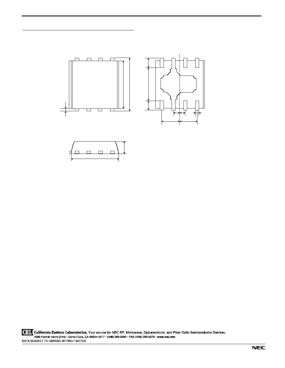
PACKAGE DIMENSIONS
(Units in mm)
PACKAGE OUTLINE TU
UPD5702TU
0.1
2.0
2.2
0.4
0.4
1.4
0.25 0.25
0.75
0.75
0.16
2.0
0.5
Life Support Applications
These NEC products are not intended for use in life support devices, appliances, or systems where the malfunction of these products can reasonably
be expected to result in personal injury. The customers of CEL using or selling these products for use in such applications do so at their own risk and
agree to fully indemnify CEL for all damages resulting from such improper use or sale.
A Business Partner of NEC Compound Semiconductor Devices, Ltd.
02/04/2004
Top View
Bottom View
Side View

5-4
4590 Patrick Henry Drive
Santa Clara, CA 95054-1817
Telephone: (408) 919-2500
Facsimile: (408) 988-0279
Subject: Compliance with EU Directives
CEL certifies, to its knowledge, that semiconductor and laser products detailed below are compliant
with the requirements of European Union (EU) Directive 2002/95/EC Restriction on Use of Hazardous
Substances in electrical and electronic equipment (RoHS) and the requirements of EU Directive
2003/11/EC Restriction on Penta and Octa BDE.
CEL Pb-free products have the same base part number with a suffix added. The suffix ≠A indicates
that the device is Pb-free. The ≠AZ suffix is used to designate devices containing Pb which are
exempted from the requirement of RoHS directive (*). In all cases the devices have Pb-free terminals.
All devices with these suffixes meet the requirements of the RoHS directive.
This status is based on CEL's understanding of the EU Directives and knowledge of the materials that
go into its products as of the date of disclosure of this information.
Restricted Substance
per RoHS
Concentration Limit per RoHS
(values are not yet fixed)
Concentration contained
in CEL devices
-A
-AZ
Lead (Pb)
< 1000 PPM
Not Detected
(*)
Mercury
< 1000 PPM
Not Detected
Cadmium
< 100 PPM
Not Detected
Hexavalent Chromium
< 1000 PPM
Not Detected
PBB
< 1000 PPM
Not Detected
PBDE
< 1000 PPM
Not Detected
If you should have any additional questions regarding our devices and compliance to environmental
standards, please do not hesitate to contact your local representative.
Important Information and Disclaimer: Information provided by CEL on its website or in other communications concerting the substance
content of its products represents knowledge and belief as of the date that it is provided. CEL bases its knowledge and belief on information
provided by third parties and makes no representation or warranty as to the accuracy of such information. Efforts are underway to better
integrate information from third parties. CEL has taken and continues to take reasonable steps to provide representative and accurate
information but may not have conducted destructive testing or chemical analysis on incoming materials and chemicals. CEL and CEL
suppliers consider certain information to be proprietary, and thus CAS numbers and other limited information may not be available for
release.
In no event shall CEL's liability arising out of such information exceed the total purchase price of the CEL part(s) at issue sold by CEL to
customer on an annual basis.
See CEL Terms and Conditions for additional clarification of warranties and liability.