 | –≠–ª–µ–∫—Ç—Ä–æ–Ω–Ω—ã–π –∫–æ–º–ø–æ–Ω–µ–Ω—Ç: CS4294-JQ | –°–∫–∞—á–∞—Ç—å:  PDF PDF  ZIP ZIP |

Preliminary Product Information
This document contains information for a new product.
Cirrus Logic reserves the right to modify this product without notice.
1
Copyright
Cirrus Logic, Inc. 2000
(All Rights Reserved)
P.O. Box 17847, Austin, Texas 78760
(512) 445 7222 FAX: (512) 445 7581
http://www.cirrus.com
FEATURES
n
AC `97 2.0 compatible
n
20-bit quad output and 18-bit dual stereo input
codec with fixed 48 kHz sampling rate
n
Dedicated ADC for enhanced digital docking
n
Three analog line-level stereo inputs for connec-
tion from LINE IN, CD, and AUX
n
High quality pseudo-differential CD input
n
Dual stereo line level output with independent 6-
bit volume control
n
6 General Purpose I/O pins
n
Meets or exceeds Microsoft's
Æ
PC 98 and PC 99
audio performance requirements
n
CrystalClearTM Stereo Enhancement
DESCRIPTION
The CS4294 is an AC `97 compatible Audio Codec
designed for PC multimedia systems. Using the in-
dustry leading CrystalClearTM delta-sigma and
mixed signal technology, the CS4294 is ideal for
PC 98-compliant desktop, notebook, and enter-
tainment PCs, where high-quality audio features
are required. The CS4294 offers four channels of
D/A and A/D conversion along with analog mixing
and stereo enhancement processing. For multi-
channel audio systems, the CS4294 can provide
four audio channels. The CS4294 provides an en-
hanced digital docking mode for portable
applications by providing a dedicated ADC capture
path from the analog input mixer.
ORDERING INFORMATION
CS4294-
KQ
48-pin TQFP 9x9x1.4mm
CS4294
-JQ
48-pin TQFP 9x9x1.4mm
VOL
MUTE
MUTE
MUTE
MUTE
VOL
VOL
VOL
+20dB
DAC
3D
STEREO TO
MONO MIXER
VOL
VOL
OUTPUT
BUFFER
OUTPUT
BUFFER
MASTER VOLUME
ALTERNATE VOLUME
MAIN D/A
CONVERTERS
PCM_OUT
PCM OUT
PATH
STEREO
INPUT
MIXER
STEREO
OUTPUT
MIXER
MIC1
AUX
CD
LINE
Mode Control
SYNC
SDATA_OUT
MUTE
VOL
ADC
INPUT
MUX
VOL
MUTE
ADC
MAIN ADC GAIN
ADC
DAC
RESET#
ALT_LINE_OUT
LINE_OUT
GPIO
BIT_CLK
SDATA_IN
AC-Link Interface
2
/
2
/
2
/
2
/
2
/
2
/
2
/
6
/
3
/
2
/
SoundFusion
Æ
Audio/Docking Codec '97 (AMC'97)
CS4294
FEB `00
DS326PP4

CS4294
2
DS326PP4
TABLE OF CONTENTS
1. CHARACTERISTICS AND SPECIFICATIONS ........................................................................ 5
AUDIO ANALOG CHARACTERISTICS.................................................................................... 5
ABSOLUTE MAXIMUM RATINGS ........................................................................................... 6
RECOMMENDED OPERATING CONDITIONS ....................................................................... 6
MIXER CHARACTERISTICS.................................................................................................... 6
DIGITAL CHARACTERISTICS ................................................................................................. 6
SERIAL PORT TIMING............................................................................................................. 7
2. GENERAL DESCRIPTION ..................................................................................................... 10
2.1 Overview .......................................................................................................................... 10
2.2 Modes of Operation ......................................................................................................... 10
2.2.1 Mode 0 ................................................................................................................ 10
2.2.2 Mode 1 ................................................................................................................ 10
3. DIGITAL SECTION ................................................................................................................. 10
3.1 AC-Link ............................................................................................................................ 10
3.2 Control registers ............................................................................................................... 11
4. ANALOG SECTION ................................................................................................................ 11
4.1 Audio Output Mixer .......................................................................................................... 12
4.2 Audio Input Mux ............................................................................................................... 12
4.3 Audio Input Mixer ............................................................................................................. 12
4.4 Audio Volume Control ...................................................................................................... 12
5. AC `97 ..................................................................................................................................... 12
5.1 AC `97 Frame Definition ................................................................................................... 12
5.2 AC-Link Serial Data Output Frame .................................................................................. 12
5.3 AC-Link Audio Output Frame ........................................................................................... 13
5.3.1 Serial Data Output Slot Tags (Slot 0)................................................................... 13
5.3.2 Register Address (Slot 1) ..................................................................................... 13
5.3.3 Register Write Data (Slot 2) ................................................................................. 14
5.3.4 Playback Data (Slots 3-11) .................................................................................. 14
5.3.5 GPIO Data (Slot12) .............................................................................................. 14
5.4 AC-Link Audio Input Frame .............................................................................................. 14
5.4.1 Serial Data Input Slot Tag Bits (Slot 0) ............................................................... 14
5.4.2 Read-Back Address Port (Slot 1) ......................................................................... 15
5.4.3 Read-Back Data Port (Slot 2)............................................................................... 15
5.4.4 PCM Capture Data (Slot 3-11) ............................................................................. 15
5.4.5 GPIO Pin Status (Slot 12) .................................................................................... 15
Contacting Cirrus Logic Support
For a complete listing of Direct Sales, Distributor, and Sales Representative contacts, visit the Cirrus Logic web site at:
http://www.cirrus.com/corporate/contacts/
CrystalClear is a trademark of Cirrus Logic, Inc.
SoundFusion is a registered trademark of Cirrus Logic, Inc.
Preliminary product information describes products which are in production, but for which full characterization data is not yet available. Advance prod-
uct information describes products which are in development and subject to development changes. Cirrus Logic, Inc. has made best efforts to ensure
that the information contained in this document is accurate and reliable. However, the information is subject to change without notice and is provided
"AS IS" without warranty of any kind (express or implied). No responsibility is assumed by Cirrus Logic, Inc. for the use of this information, nor for
infringements of patents or other rights of third parties. This document is the property of Cirrus Logic, Inc. and implies no license under patents, copy-
rights, trademarks, or trade secrets. No part of this publication may be copied, reproduced, stored in a retrieval system, or transmitted, in any form
or by any means (electronic, mechanical, photographic, or otherwise) without the prior written consent of Cirrus Logic, Inc. Items from any Cirrus
Logic webbiest or disk may be printed for use by the user. However, no part of the printout or electronic files may be copied, reproduced, stored in a
retrieval system, or transmitted, in any form or by any means (electronic, mechanical, photographic, or otherwise) without the prior written consent
of Cirrus Logic, Inc.Furthermore, no part of this publication may be used as a basis for manufacture or sale of any items without the prior written
consent of Cirrus Logic, Inc. The names of products of Cirrus Logic, Inc. or other vendors and suppliers appearing in this document may be trade-
marks or service marks of their respective owners which may be registered in some jurisdictions. A list of Cirrus Logic, Inc. trademarks and service

CS4294
DS326PP4
3
5.5 AC '97 Reset Modes ........................................................................................................ 15
5.5.1 Cold AC `97 Reset .............................................................................................. 15
5.5.2 Warm AC '97 Reset ............................................................................................ 15
5.5.3 AC '97 Register Reset ........................................................................................ 16
5.6 AC-Link Protocol Violation - Loss of SYNC ..................................................................... 16
6. REGISTER INTERFACE ........................................................................................................ 17
6.1 Register Descriptions ...................................................................................................... 18
6.1.1 Reset (Index 00h) ............................................................................................... 18
6.1.2 Master Volume (Index 02h) ................................................................................. 18
6.1.3 Alternate Volume (Index 04h) ............................................................................. 19
6.1.4 Microphone Volume (Index 0Eh) ......................................................................... 19
6.1.5 Stereo Analog Mixer Input Gain (Index's 10h - 12h, 16h - 18h)........................... 20
6.1.6 Input Mux Select (Index 1Ah)............................................................................... 20
6.1.7 Record Gain (Index 1Ch) ..................................................................................... 21
6.1.8 General Purpose (Index 20h)............................................................................... 21
6.1.9 Stereo Enhancement Control (Index 22h) ........................................................... 21
6.1.10 Power Down Control/Status (Index 26h)............................................................ 22
6.1.11 Extended Audio ID (Index 28h) ......................................................................... 23
6.1.12 Extended Audio Status/Control (Index 2Ah) ..................................................... 23
6.1.13 PCM Front DAC Rate (Index 2Ch) .................................................................. 23
6.1.14 PCM Surround DAC Rate (Index 2Eh) ........................................................... 23
6.1.15 PCM LFE DAC Rate (Index 30h) .................................................................... 24
6.1.16 PCM LR ADC Rate (Index 32h) ......................................................................... 24
6.1.17 Center LFE Volume (Index 36h) ........................................................................ 24
6.1.18 LR Surround Volume (Index 38h) ...................................................................... 24
6.1.19 Extended Codec ID (Index 3Ch) ....................................................................... 25
6.1.20 Extended Codec Status/Control (Index 3Eh) .................................................... 25
6.1.21 Extended Audio DAC1/ADC1 Rate (Index 40h)................................................. 26
6.1.22 Extended Audio DAC2/ADC2 (Index 44h) ......................................................... 26
6.1.23 Extended Audio DAC1/ADC1 Level (Index 46h)................................................ 26
6.1.24 Extended AudioDAC2/ADC2 Level (Index 4Ah) ................................................ 26
6.1.25 GPIO Pin Configuration (Index 4Ch).................................................................. 27
6.1.26 GPIO Pin Polarity/Type Configuration (Index 4Eh)............................................ 27
6.1.27 GPIO Pin Sticky (Index 50h) .............................................................................. 27
6.1.28 GPIO Pin Wakeup Mask (Index 4Ch) ............................................................... 28
6.1.29 GPIO Pin Status (Index 54h) ............................................................................. 28
6.1.30 AC Mode Control (Index 5Eh)............................................................................ 28
6.1.31 Vendor ID1 (Index 7Ch) ..................................................................................... 29
6.1.32 Vendor ID2 (Index 7Eh) ..................................................................................... 29
7. ANALOG HARDWARE DESCRIPTION ................................................................................. 30
7.1 Line-Level Inputs ............................................................................................................. 30
7.2 Microphone Level Inputs ................................................................................................. 30
7.3 Line Level Outputs ........................................................................................................... 31
7.4 Miscellaneous Analog Signals ......................................................................................... 31
7.5 Power Supplies ................................................................................................................ 32
8. PIN DESCRIPTIONS .............................................................................................................. 33
8.1 Digital I/O Pins ................................................................................................................. 33
8.2 Analog I/O Pins ................................................................................................................ 35
8.3 Filter and Reference Pins ................................................................................................ 36
8.4 Power Supplies ................................................................................................................ 37
9. PARAMETER AND TERM DEFINITIONS .............................................................................. 38
10. REFERENCES ...................................................................................................................... 39
11. PACKAGE DIMENSIONS .................................................................................................... 40

CS4294
4
DS326PP4
LIST OF FIGURES
Figure 1. Power Up Timing.............................................................................................................. 8
Figure 2. Clocks .............................................................................................................................. 8
Figure 3. Codec Ready from Startup or Fault Condition ................................................................. 8
Figure 4. Data Setup and Hold........................................................................................................ 9
Figure 5. PR4 Powerdown .............................................................................................................. 9
Figure 6. Test Mode ........................................................................................................................ 9
Figure 7. AC-link Connections....................................................................................................... 11
Figure 8. Mixer Diagram................................................................................................................ 11
Figure 9. AC-link Input and Output Framing.................................................................................. 12
Figure 10. Line Inputs.................................................................................................................... 30
Figure 11. Differential CDROM In ................................................................................................. 30
Figure 12. PC `99 Microphone Pre-amplifier ................................................................................. 31
Figure 13. Headphones Driver ...................................................................................................... 32
Figure 14. Voltage Regulator ........................................................................................................ 32
LIST OF TABLES
Table 1. Mixer Registers ............................................................................................................... 17
Table 2. Alternate Line-Out and Master Mono Attenuation ........................................................... 19
Table 3. Analog Mixer Input Gain Values...................................................................................... 19
Table 4. Stereo Volume Register Index ........................................................................................ 20
Table 5. Input Mux Selection......................................................................................................... 20
Table 6. 6 Channel Volume Attenuation........................................................................................ 24
Table 7. GPIO Input/Output Configuration .................................................................................... 27
Table 8. Slot Assignments............................................................................................................ 28
Table 9. Reg. 7Eh Defined Part ID's ............................................................................................. 29
CS4294
DS326PP4
5
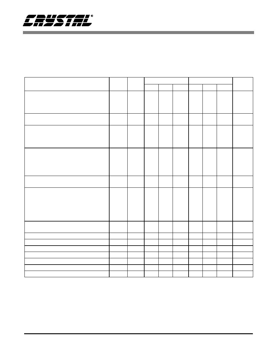
1. CHARACTERISTICS AND SPECIFICATIONS
AUDIO ANALOG CHARACTERISTICS
(Standard test conditions unless otherwise noted:
T
ambient
= 25∞ C, AVdd = 5.0 V ±5%, DVdd = 3.3 V ±5%; 1 kHz Input Sine wave; Sample Frequency, Fs = 48 kHz;
Z
AL
=10 k
/
680 pF load C
DL
= 18 pF load (Note 1); Measurement bandwidth is 20 Hz - 20 kHz, 18-bit linear coding
for ADC, 20-bit linear coding for DAC; Mixer registers set for unity gain.
Notes: 1. Z
AL
refers to the analog output pin loading and C
DL
refers to the digital output pin loading.
2. Parameter definitions are given in the Parameter and Term Definitions section.
3. Path refers to the signal path used to generate this data. These paths are defined in the Parameter and
Term Definition section.
4. Typical measured with Z
AL
= 47 k
/680 pF load.
5. This specification is guaranteed by silicon characterization, it is not production tested.
Parameter (Note 2)
Symbol
Path
(Note 3)
CS4294-KQ
CS4294-JQ
Unit
Min Typ
Max
Min Typ
Max
Full Scale Analog Input Voltage
Line Inputs
Mic Inputs
(20 dB=0)
Mic Inputs
(20 dB=1)
A-D
A-D
A-D
0.91
0.91
0.091
1.00
1.00
0.10
-
-
-
0.91
0.91
0.091
1.00
1.00
0.10
-
-
-
V
RMS
V
RMS
V
RMS
Full Scale Output Voltage (Note 4)
Line and Alternate Line Outputs
D-A
0.91
1.0
1.13
0.91
1.0
1.13
V
RMS
Frequency Response
Analog
Ac = ± 0.5 dB
DAC
Ac = ± 0.5 dB
ADC
Ac = ± 0.5 dB
FR
A-A
D-A
A-D
20
20
20
-
-
-
20,000
20,000
20,000
20
20
20
-
-
-
20,000
20,000
20,000
Hz
Hz
Hz
Dynamic Range
Stereo Analog inputs to LINE_OUT
Mono Analog inputs to LINE_OUT
DAC Dynamic Range
ADC Dynamic Range
DR
A-A
A-A
D-A
A-D
90
85
85
85
95
90
90
90
-
-
-
-
-
-
-
-
90
85
87
85
-
-
-
-
dB FS A
dB FS A
dB FS A
dB FS A
DAC SNR (-20 dB FS input w/
CCIR-RMS filter on output)
SNR
D-A
-
63
-
-
-
-
dB
Total Harmonic Distortion + Noise
(-3 dB FS input signal):
Line/Alternate Line Output
DAC
ADC
(all inputs except phone/mic)
ADC
(phone/mic)
THD+N
A-A
D-A
A-D
A-D
-
-
-
-
-94
-86
-87
-87
-80
-80
-80
-74
-
-
-
-
-
-
-
-
-74
-74
-74
-74
dB FS A
dB FS A
dB FS A
dB FS A
Power Supply Rejection Ratio
(1 kHz, 0.5 V
RMS
w/ 5 V DC offset)(Note 5)
40
60
-
-
40
-
dB
Interchannel Isolation
70
87
-
-
87
-
dB
Spurious Tone
(Note 5)
-
-100
-
-
-100
-
dB FS
Input Impedance
(Note 5)
10
-
-
10
-
-
k
External Load Impedance
10
-
-
10
-
-
k
Output Impedance
(Note 5)
-
730
-
-
730
-
Input Capacitance
(Note 5)
-
5
-
-
5
-
pF
Vrefout
2.0
2.3
2.4
2.0
2.3
2.4
V