
100-MHz Pentium
Æ
II Clock Synthesizer/Driver with
Spread Spectrum for Mobile or Desktop PCs
CY2280
Cypress Semiconductor Corporation
∑
3901 North First Street
∑
San Jose
∑
CA 95134
∑
408-943-2600
Document #: 38-07207 Rev. *A
Revised December 08, 2002
0
Features
∑ Mixed 2.5V and 3.3V operation
∑ Clock solution for PentiumÆ II, and other similar pro-
cessor-based motherboards
-- Four 2.5V CPU clocks up to 100 MHz
-- Eight 3.3V sync. PCI clocks, one free-running
-- Two 3.3V 48-MHz USB clocks
-- Three 3.3V Ref. clocks at 14.318 MHz
-- Two 2.5V APIC clocks at 14.318 MHz or PCI/2
∑ EMI control
-- Spread spectrum clocking
-- Factory-EPROM programmable spread spectrum
margin
-- Factory-EPROM programmable output drive and
slew rate
∑ Factory-EPROM programmable CPU clock frequencies
for custom configurations
∑ Available in space-saving 48-pin SSOP package
Functional Description
The CY2280 is a Spread Spectrum clock synthesizer/driver for
a Pentium II, or other similar processor-based PC requiring
100-MHz support. All of the required system clocks are provid-
ed in a space-saving 48-pin SSOP package. The CY2280 can
be used with the CY231x for a total solution for systems with
SDRAM.
The CY2280 provides the option of spread spectrum clocking
on the CPU and PCI clocks for reduced EMI. A downspread
percentage is introduced when the SEL_SS input is asserted.
The device can be run without spread spectrum when the
SEL_SS input is deasserted. The percentage of spreading is
EPROM-programmable to optimize EMI-reduction.
The CY2280 has power-down, CPU stop, and PCI stop pins
for power management control. The signals are synchronized
on-chip, and ensure glitch-free transitions on the outputs.
When the CPU_STOP input is asserted, the CPU clock out-
puts are driven LOW. When the PCI_STOP input is asserted,
the PCI clock outputs (except the free-running PCI clock) are
driven LOW. When the PWR_DWN pin is asserted, the refer-
ence oscillator and PLLs are shut down, and all outputs are
driven LOW.
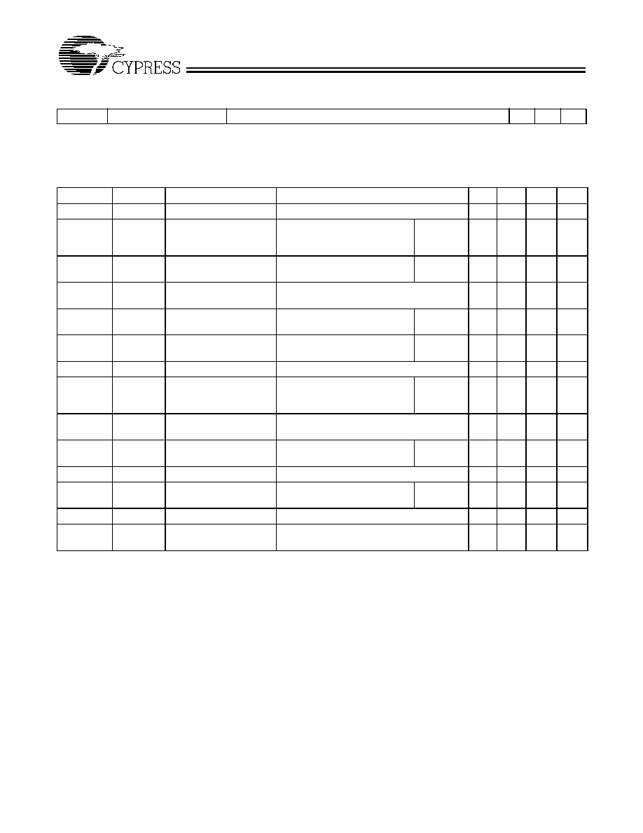
CY2280 Selector Guide
CY2280 Configuration Options
Clock Outputs
≠1
≠11S
≠21S
CPU (66.6, 100 MHz)
4
4
4
PCI (CPU/2, CPU/3)
8
8
8
USB (48 MHz)
2
2
2
APIC (14.318 MHz)
2
2
--
APIC (PCI/2)
--
--
2
Reference (14.318 MHz)
3
3
3
CPU-PCI delay
1.5
-
4.0 ns
1.5
-
4.0 ns
1.5
-
4.0 ns
CPU-APIC delay
--
--
2.0≠4.5 ns
Spread Spectrum (Downspread)
N/A
-
0.6%
-
0.6%
Pentium is a registered trademark of Intel Corporation.
Logic Block Diagram
EPROM
XTALOUT
XTALIN
APIC [0:1]
14.318
MHz
OSC.
SEL0
V
DDAPIC
CPU
PLL
SEL100
Delay
REF [0-2]
CPUCLK [0-3]
V
DDCPU
PCI [1-7]
PCICLK_F
STOP
STOP
LOGIC
LOGIC
SEL1
USBCLK [0:1]
SYS PLL
CPU_STOP
PWR_DWN
Divider
PCI_STOP
V
DDPCI
V
DDPCI
V
DDREF
V
DDUSB
-1
-2
SEL_SS

CY2280
Document #: 38-07207 Rev. *A
Page 2 of 12
Pin Summary
Name
Pins
Description
V
DDPCI
15, 9
3.3V Digital voltage supply for PCI clocks
V
DDUSB
21
3.3V Digital voltage supply for USB clocks
V
DDREF
48
3.3V Digital voltage supply for REF clocks
V
DDAPIC
46
2.5V Digital voltage supply for APIC clocks
V
DDCPU
41, 37
2.5V Digital voltage supply for CPU clocks
AV
DD
33, 19
Analog voltage supply, 3.3V
V
SS
3, 6, 12, 18, 20, 24, 32, 34, 38, 43 Ground
XTALIN
[1]
4
Reference crystal input
XTALOUT
[1]
5
Reference crystal feedback
PCI_STOP
31
Active LOW control input to stop PCI clocks
CPU_STOP
30
Active LOW control input to stop CPU clocks
PWR_DWN
29
Active LOW control input to power down device
SEL_SS
28
Spread spectrum select input (-11S and -21S options)
N/C
28
Spread spectrum select input (-1 option)
SEL0
27
CPU frequency select input, bit 0 (see Function Table)
SEL1
26
CPU frequency select input, bit 1 (see Function Table)
SEL100
25
CPU frequency select input, selects between 100 MHz and 66.6 MHz
(see Function Table)
CPUCLK[0:3]
40, 39, 36, 35
CPU clock outputs
PCICLK[1:7]
8, 10, 11, 13, 14, 16, 17
PCI clock outputs, at one-half or one-third the CPU frequency of 66.6 MHz
or 100 MHz respectively
PCICLK_F
7
Free-running PCI clock output
APIC[0:1]
45, 44
APIC clock outputs
REF[0:2]
1, 2, 47
3.3V Reference clock outputs
USBCLK[0:1]
22, 23
USB clock outputs
RESERVED
42
Reserved
Note:
1.
For best accuracy, use a parallel-resonant crystal, C
LOAD
= 18 pF.
Pin Configurations
1
2
3
4
5
6
7
8
9
10
11
12
33
32
31
30
29
25
26
27
28
36
35
REF0
34
13
14
15
16
17
18
19
20
21
22
23
24
45
44
43
42
41
37
38
39
40
48
47
46
REF1
V
SS
XTALIN
XTALOUT
PCICLK_F
V
SS
PCICLK1
PCICLK2
V
DDPCI
PCICLK3
V
SS
PCICLK4
V
DDPCI
PCICLK5
PCICLK7
V
SS
AV
DD
V
SS
V
DDUSB
USBCLK0
USBCLK1
V
SS
V
DDREF
REF2
V
DDAPIC
APIC0
APIC1
V
SS
RESERVED
V
DDCPU
CPUCLK0
CPUCLK1
V
SS
V
DDCPU
CPUCLK2
CPUCLK3
V
SS
AV
DD
PCI_STOP
PWR_DWN
N/C
SEL0
SEL1
SEL100
CPU_STOP
V
SS
PCICLK6
1
2
3
4
5
6
7
8
9
10
11
12
33
32
31
30
29
25
26
27
28
36
35
REF0
34
13
14
15
16
17
18
19
20
21
22
23
24
45
44
43
42
41
37
38
39
40
48
47
46
REF1
V
SS
XTALIN
XTALOUT
PCICLK_F
V
SS
PCICLK1
PCICLK2
V
DDPCI
PCICLK3
V
SS
PCICLK4
V
DDPCI
PCICLK5
PCICLK7
V
SS
AV
DD
V
SS
V
DDUSB
USBCLK0
USBCLK1
V
SS
V
DDREF
REF2
V
DDAPIC
APIC0
APIC1
V
SS
RESERVED
V
DDCPU
CPUCLK0
CPUCLK1
V
SS
V
DDCPU
CPUCLK2
CPUCLK3
V
SS
AV
DD
PCI_STOP
PWR_DWN
SEL_SS
SEL0
SEL1
SEL100
CPU_STOP
V
SS
PCICLK6
CY2280-1
CY2280-11S
CY2280-21S
48-
pi
n S
S
O
P
(
T
op
V
i
e
w
)
4
8
-pi
n
S
S
OP
(T
op V
i
ew
)

CY2280
Document #: 38-07207 Rev. *A
Page 3 of 12
Function Table (-11S Option)
SEL100
SEL1
SEL0
SEL_SS
[2]
CPU/PCI
Ratio
CPUCLK
PCICLK_F
PCICLK
REF
APIC USBCLK
0
0
0
N/A
2
Hi-Z
Hi-Z
Hi-Z
Hi-Z
Hi-Z
0
0
1
N/A
2
Reserved
Reserved
14.318 MHz
14.318 MHz
48 MHz
0
1
0
N/A
2
Reserved
Reserved
14.318 MHz
14.318 MHz
48 MHz
0
1
1
0 (downspread)
2
66.66 MHz 33.33 MHz
14.318 MHz
14.318 MHz
48 MHz
0
1
1
1 (no spread)
2
66.66 MHz 33.33 MHz
14.318 MHz
14.318 MHz
48 MHz
1
0
0
N/A
3
TCLK/2
TCLK/6
TCLK
[3]
TCLK
[3]
TCLK/2
1
0
1
N/A
3
Reserved
Reserved
14.318 MHz
14.318 MHz
48 MHz
1
1
0
N/A
3
Reserved
Reserved
14.318 MHz
14.318 MHz
48 MHz
1
1
1
0 (downspread)
3
100 MHz
33.33 MHz
14.318 MHz
14.318 MHz
48 MHz
1
1
1
1 (no spread)
3
100 MHz
33.33 MHz
14.318 MHz
14.318 MHz
48 MHz
Function Table (-21S Option)
SEL100
SEL1
SEL0
SEL_SS
[2]
CPU/PCI
Ratio
CPUCLK
PCICLK_F
PCICLK
REF
APIC USBCLK
0
0
0
N/A
2
Hi-Z
Hi-Z
Hi-Z
Hi-Z
Hi-Z
0
0
1
N/A
2
Reserved
Reserved
14.318 MHz
Reserved
48 MHz
0
1
0
N/A
2
Reserved
Reserved
14.318 MHz
Reserved
48 MHz
0
1
1
0 (downspread)
2
66.66 MHz 33.33 MHz
14.318 MHz
16.67 MHz
48 MHz
0
1
1
1 (no spread)
2
66.66 MHz 33.33 MHz
14.318 MHz
16.67 MHz
48 MHz
1
0
0
N/A
3
TCLK/2
TCLK/6
TCLK
[3]
TCLK/12
[3]
TCLK/2
1
0
1
N/A
3
Reserved
Reserved
14.318 MHz
Reserved
48 MHz
1
1
0
N/A
3
Reserved
Reserved
14.318 MHz
Reserved
48 MHz
1
1
1
0 (downspread)
3
100 MHz
33.33 MHz
14.318 MHz
16.67 MHz
48 MHz
1
1
1
1 (no spread)
3
100 MHz
33.33 MHz
14.318 MHz
16.67 MHz
48 MHz
Actual Clock Frequency Values
Clock Output
Target Frequency
(MHz)
Actual Frequency
(MHz)
PPM
CPUCLK
66.67
66.654
≠195
CPUCLK
100
99.77
≠2346
USBCLK
48.0
48.008
167
Power Management Logic
CPU_STOP
PCI_STOP
PWR_DWN
CPUCLK
PCICLK
PCICLK_F
Other
Clocks
Osc.
PLLs
X
X
0
Low
Low
Low
Low
Off
Off
0
0
1
Low
Low
Running
Running
Running Running
0
1
1
Low
Running
Running
Running
Running Running
1
0
1
Running
Low
Running
Running
Running Running
1
1
1
Running
Running
Running
Running
Running Running
Notes:
2.
Target frequency is modulated by percentage shown (max.) when SEL_SS = 0.
3.
TCLK supplied on the XTALIN pin in Test Mode.

CY2280
Document #: 38-07207 Rev. *A
Page 4 of 12
Maximum Ratings
(Above which the useful life may be impaired. For user guide-
lines, not tested.)
Supply Voltage .................................................≠0.5 to + 7.0V
Input Voltage ............................................ ≠0.5V to V
DD
+ 0.5
Storage Temperature (Non-Condensing) ... ≠65
∞
C to +150
∞
C
Junction Temperature ............................................... +150
∞
C
Package Power Dissipation.............................................. 1W
Static Discharge Voltage........................................... > 2000V
(per MIL-STD-883, Method 3015, like V
DD
pins tied together)
Operating Conditions
[4]
Parameter
Description
Min.
Max.
Unit
AV
DD
, V
DDPCI
,
V
DDUSB
, V
DDREF
Analog and Digital Supply Voltage
3.135
3.465
V
V
DDCPU
CPU Supply Voltage
2.375
2.625
V
V
DDAPIC
APIC Supply Voltage
2.375
2.625
V
T
A
Operating Temperature, Ambient
0
70
∞
C
C
L
Max. Capacitive Load on
CPUCLK
PCICLK
APIC, REF
USB
20
30
20
20
pF
f
(REF)
Reference Frequency, Oscillator Nominal Value
14.318
14.318
MHz
t
PU
Power-up time for all VDD's to reach minimum specified voltage (power
ramps must be monotonic)
0.05
50
ms
Electrical Characteristics
Over the Operating Range
Parameter
Description
Test Conditions
Min. Max. Unit
V
IH
High-level Input Voltage
Except Crystal Inputs
[5]
2.0
V
V
IL
Low-level Input Voltage
Except Crystal Inputs
[5]
0.8
V
V
OH
High-level Output Voltage
[6]
V
DDCPU
= V
DDAPIC
= 2.375V
I
OH
= 12 mA CPUCLK
2.0
V
I
OH
= 18 mA APIC
V
OL
Low-level Output Voltage
[6]
V
DDCPU
= V
DDAPIC
= 2.375V
I
OL
= 12 mA
CPUCLK
0.4
V
I
OL
= 18 mA
APIC
V
OH
High-level Output Voltage
[6]
V
DDPCI
, AV
DD
, V
DDREF
, V
DDUSB
= 3.135V I
OH
= 14.5 mA PCICLK
2.4
V
I
OH
= 16 mA USBCLK
I
OH
= 16 mA REF
V
OL
Low-level Output Voltage
[6]
V
DDPCI
, AV
DD
, V
DDREF
,
V
DDUSB
= 3.135V I
OL
= 9.4 mA PCICLK
0.4V
V
I
OL
= 9 mA
USBCLK
I
OL
= 9 mA
REF
I
IH
Input High Current
V
IH
= V
DD
≠10
+10
µ
A
I
IL
Input Low Current
V
IL
= 0V
10
µ
A
I
OZ
Output Leakage Current
Three-state
≠10
+10
µ
A
I
DD25
Power Supply Current for
2.5V Clocks
[6]
V
DDCPU
= 2.625V, V
IN
= 0 or V
DD
, Loaded Outputs, CPU = 66.6 MHz
70
mA
I
DD25
Power Supply Current for
2.5V Clocks
[6]
V
DDCPU
= 2.625V, V
IN
= 0 or V
DD
, Loaded Outputs, CPU = 100 MHz
100
mA
I
DD33
Power Supply Current for
3.3V Clocks
[6]
V
DD
= 3.465V, V
IN
= 0 or V
DD
, Loaded Outputs
170
mA
I
DDS
Power-down Current
[6]
Current draw in power-down state
500
µ
A
CY2280
Document #: 38-07207 Rev. *A
Page 5 of 12
Notes:
4.
Electrical parameters are guaranteed with these operating conditions.
5.
Crystal Inputs have CMOS thresholds.
6.
Parameter is guaranteed by design and characterization. Not 100% tested in production.
Electrical Characteristics
Over the Operating Range
Parameter
Description
Test Conditions
Min. Max. Unit
Switching Characteristics
[6, 7]
Parameter
Output
Description
Test Conditions
Min.
Typ.
Max.
Unit
t
1
All
Output Duty Cycle
[8]
t
1
= t
1A
˜
t
1B
45
50
55
%
t
2
CPUCLK,
APIC
CPU and APIC Clock
Rising and Falling Edge
Rate
Between 0.4V and 2.0V
-1,-11S,
-21S
1.0
4.0
V/ns
t
2
PCICLK
PCI Clock Rising and
Falling Edge Rate
Between 0.4V and 2.4V
-1,-11S,
-21S
1.0
4.0
V/ns
t
2
USBCLK,
REF
USB, REF Rising and
Falling Edge Rate
Between 0.4V and 2.4V
0.5
2.0
V/ns
t
3
CPUCLK
CPU Clock Rise Time
Between 0.4V and 2.0V
-1,-11S,
-21S
0.4
1.6
ns
t
4
CPUCLK
CPU Clock Fall Time
Between 2.0V and 0.4V
-1,-11S,
-21S
0.4
1.6
ns
t
5
CPUCLK
CPU-CPU Clock Skew
Measured at 1.25V
100
175
ps
t
6
CPUCLK,
PCICLK
CPU-PCI Clock Skew
[9]
Measured at 1.25V for 2.5V
clocks, and at 1.5V for 3.3V
clocks
-1,-11S,
-21S
1.5
4.0
ns
t
7
PCICLK,
PCICLK
PCI-PCI Clock Skew
Measured at 1.5V
250
ps
t
8
CPUCLK,
APIC
CPU-APIC Clock
Skew
[10]
Measured at 1.25V for 2.5V
clocks
-21S
2.0
4.5
ns
t
9
APIC
APIC-APIC Clock Skew
Measured at 1.25V
100
175
ps
t
10
CPUCLK
Cycle-Cycle Clock Jitter
Measured at 1.25V
-1,-11S,
-21S
200
250
ps
t
11
PCICLK
Cycle-Cycle Clock Jitter
Measured at 1.5V
250
500
ps
t
12
CPUCLK,
PCICLK
Power-up Time
CPU, PCI clock stabilization from
power-up
3
ms
Notes:
7.
All parameters specified with loaded outputs.
8.
Duty cycle is measured at 1.5V when V
DD
= 3.3V. When V
DD
= 2.5V, duty cycle is measured at 1.25V.
9.
PCI lags CPU for -11S and -21S options.
10. APIC lags CPU for -21S option.