JZC-22F JZC-22F
2
JZC-22F
3
20.3
×
16.8
×
20.2 22.5
×
16.8
×
20.2 20.0
×
16.0
×
20.3
JZC-22F JZC-22F
2
JZC-22F
3
Features
Small size, light weight .Low coil power consumption.
Switching capacity can reach 20A.
PC board mounting.
Suitable for household electrical appliance, automation system, electronic equipment, instrument and meter application.
TV-5
f
TV-8 Remote control TV receivers, monitor display, audio equipment high and rushing current application.
Ordering Information
JZC-22F S C 5 D DC12V
1 2 3 4 5 6
1 Part number
JZC-22F JZC-22F
2
JZC-22F
3
2 Enclosure
S: Sealed type
F: Dust cover
3 Contact arrangement
A:1A
B:1B
C:1C
4 Contact Rating
7A,12A,15A/120VAC 28DC
6A,7A/220VAC
6A/250VAC TV-5
JZC-22F
2
20A/125VAC 28VDC
10A/220VAC
JZC-22F
3
20A/125VAC 28VDC
16A/277VAC TV-8
5 Coil power consumption
L:0.36W
D:0.45W
6 Coil rated Voltage(V)
DC:3,6,9,12,24,48
Contact Data
Contact Arrangement
1A SPSTNO
f
1B SPSTNC
f
1C SPDT(B-M)
Contact Material
Ag CdO Ag SnO
2
Contact Rating
resistive:5A,12A,15A,20A/120VAC,28VDC; 3A;6A,7A,10A/220VAC ;
inductive:10A/250VAC; 15A/28VDC (rushing current 80A) (JZC-22FT only)
lamp:TV-5
note:1) 20A/125VDC,28VDC &10A/220VAC JZC-22F
2
only
2) 20A/125V,28VDC,16A/277VAC&TV-8 JZC-22F
3
only
Max. Switching Power
420W 1800VA
Max. Switching Voltage
110VDC 380VAC Max. Switching Current:20A rushing current 80A
Contact Resistance & Voltage drop
100m item 3.12 of IEC255-7
Electrical
10
5
item 3.30 of IEC255-7
Operation
life
Mechanical
10
7
item 3.31 of IEC255-7
Coil Parameter
Coil voltage
VDC
Dash
numbers
Rated
Max.
Coil resistance
±
10%
Pickup
voltage
VDC(max)
(75%of rated
voltage )
release
voltage
VDC(min)
(10% of
rated
voltage)
Coil power
consumption
W
Operate
Time
ms
Release
Time
ms
003-360
3
3.9
25
2.25
0.3
006-360
6
7.8
100
4.50
0.6
009-360
9
11.7
225
6.75
0.9
012-360
12
15.6
400
9.00
1.2
024-360
24
31.2
1600
18.0
2.4
048-360
48
62.4
6400
36.0
4.8
0.36
15
5
003-450
3
3.9
20
2.25
0.3
006-450
6
7.8
80
4.50
0.6
009-450
9
11.7
180
6.75
0.9
012-450
12
15.6
320
9.00
1.2
024-450
24
31.2
1280
18.0
2.4
048-450
48
62.4
5120
36.0
4.8
0.45
15
5
CAUTION
: 1.The use of any coil voltage less than the rated coil voltage will compromise the operation of the relay.
2.Pickup and release voltage are for test purposes only and are not to be used as design criteria.
93
VDE
E158859
R9452085
CH0050402--2000 40001299
www.dblectro.com
Operation condition
Insulation Resistance
100M min (at 500VDC)
Item 7 of IEC255-5
Dielectric Strength
Between contacts
Between contact and coil
50Hz 750V JZC-22F
3
:1000V
50Hz 1500V
50Hz 2500V JZC-22F
2
&JZC-22F
3
Item 6 of IEC255-5
Item 6 of IEC255-5
Item 6 of IEC255-5
Shock resistance
100m/s
2
11ms
IEC68-2-27 Test Ea
Vibration resistance
10~55Hz double amplitude 1.5mm
IEC68-2-6 Test Fc
Terminals strength
10N
IEC68-2-21 Test Ua1
Solderability
235
x
2
3
x
0.5s
IEC68-2-20 Test Ta method 1
Ambient Temperature
-40~70
JZC-22F
3
:85
Relative Humidity
85% (at 40
)
IEC68-2-3Test Ca
Mass
13g . 16g(JZC-22F
2
) 10g(JZC-22F
3
)
Qualification inspection:
Perform the qualification test as specified in the table
of IEC255-19-1 and minimum sample size 24.
Safety approvals
Safety approval
UL&CUR
VDE
T
ü
V
CCEE
Load
15A/125VAC,28VDCTV-5
10A/250VAC 28VDC
6A/250VAC
6A/250VAC
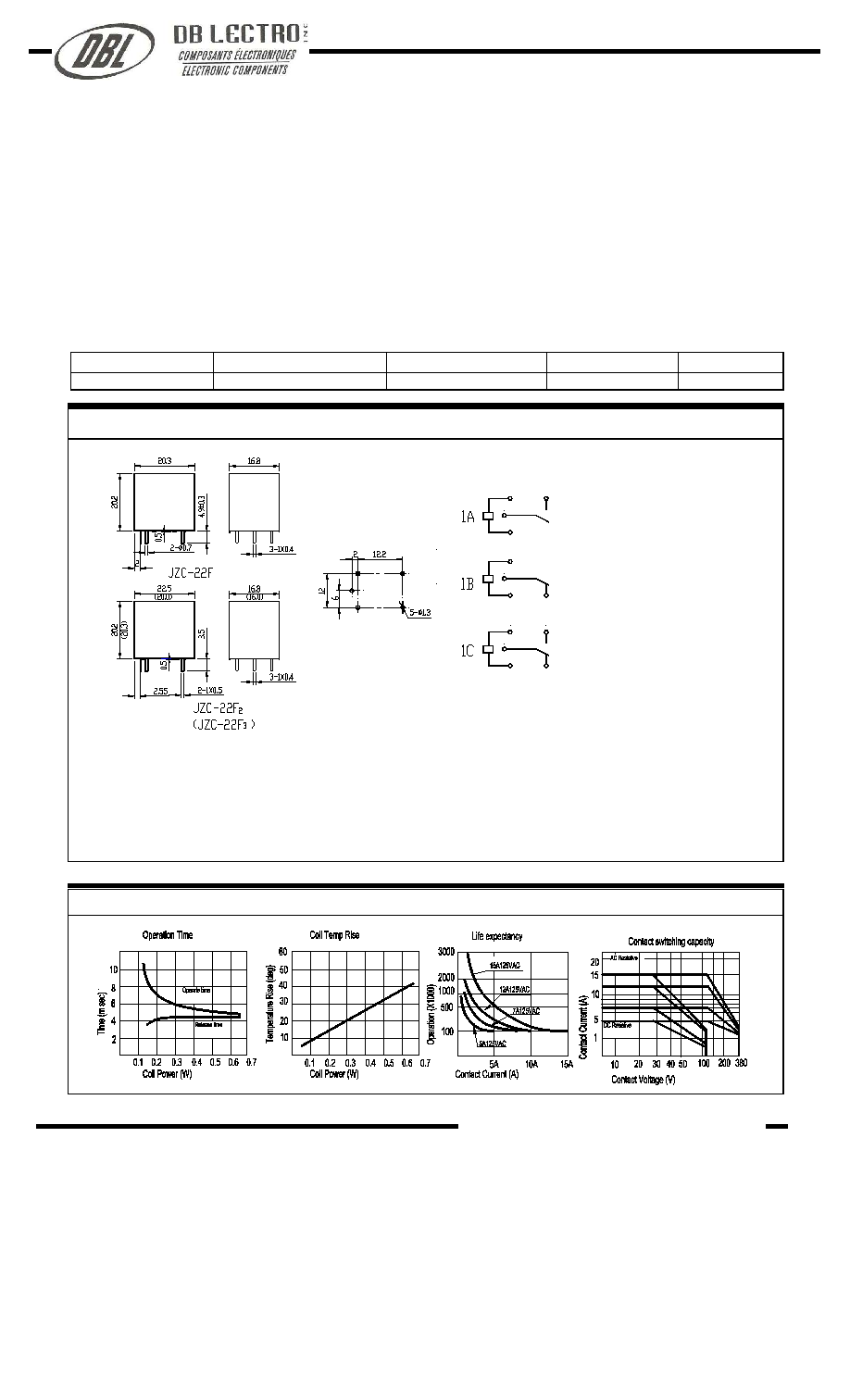
Dimensions (Unit: mm)
Reference Data
NOTES
1).Dimensions are in millimeter.
2).Inch equivalents are given for general information only.
JZC-22F JZC-22F
2
JZC-22F
3
Dimensions
Mounting
(Bottom views)
mm inch
0.4
0.016
0.5
0.020
0.7 0.027
1.0
0.039
1.3
0.051
2.0
0.079
2.55
0.100
3.5
0.138
4.5
0.177
6.0
0.236
12.0
0.472
12.2
0.480
16.8
0.661
20.2
0.795
20.3
0.799
22.5 0.866
Wiring diagram
(Bottom views)
www.dblectro.com