4-37
Dialight Corporation ∑ 1501 Route 34 South ∑ Farmingdale, NJ 07727 ∑ TEL: (732) 919-3119 ∑ FAX: (732) 751-5778 ∑www.dialight.com
4
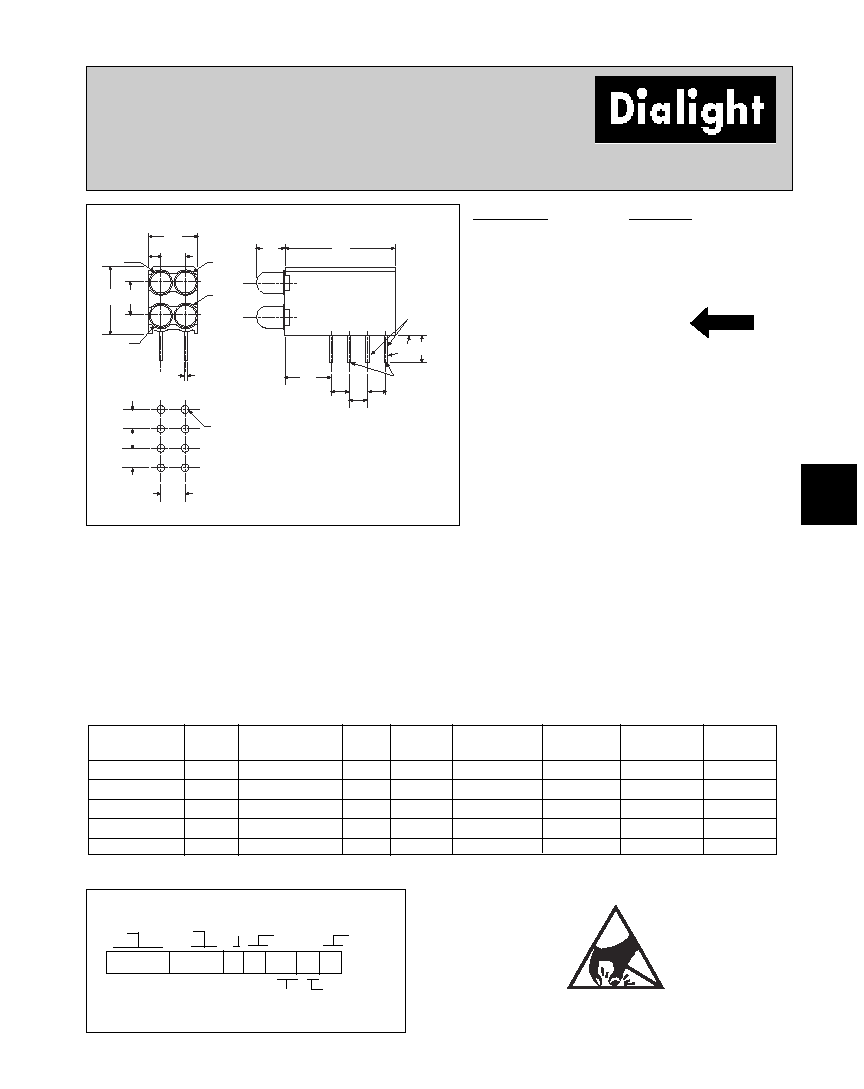
3mm
LED CBI
Æ
Circuit Board Indicator
High Density Dual Bi-Level
569-010x-xxx
6.60
[.260]
3.35
[.132]
1.63
[.064]
POS. 1
POS. 3
POS. 4
POS. 2
8.89
[.350]
4.57
[.180]
2.29
[.090]
3.81
[.150]
14.73
6.10
[.240]
2.54
[.100] 2.54
[.100]
2.54
[.100]
3.68
±
.25
[.145
±
.010]
90
∞
TYP
.46 SQ NOM TYP
[.018]
3.35
[.132]
2.54
±
.05
[.100
±
.002]
2.54
±
.05
[.100
±
.002]
2.54
±
.05
[.100
±
.002]
ÿ 1.02
±
.05
[.040
±
.002]
TYP (8)
ANODE
(+) LEAD
TOP
LED
PART NO.
COLOR*
569-0101-111
Red
569-0102-222
Green
569-0103-333
Yellow
569-0107-777
Orange
569-0108-888
Blue
≥
* LED 1, LED 2, LED 3, LED 4
Peak
I
V
V
F
Test
Viewing
LED
Part Number
Color
Wavelength nm
mcd
Volts
Current (mA)
Angle 2
Ω
Data sheet
Page #
569-0101-111
Red
635
10
2*
10
60∞
521-9216
4-58
569-0102-222
Green
565
12.6
2.1*
10
60∞
521-9210
4-58
569-0103-333
Yellow
585
10
2.1*
10
60∞
521-9211
4-58
569-0107-777
Orange
600
7
2.2
10
60∞
521-9498
4-58
569-0108-888
Blue
428
12
3.5
10
70∞
521-9831
4-57
Typical Operating Characteristics (T
A
=25∞C)
See LED data sheet for additional information
See page 4-70 and 4-71 for Reference Only LED Drive Circuit Examples. See page 4-72 for Pin Out
Housing Type
5 6 9 - 0 1 0 x - x x x
LED Type
Series
PART NUMBER ORDERING CODE
Color = 0) Blank 1) Red 2) Green 3) Yellow 7) Orange 8) Blue
Pos. 4
Color
Pos. 2 Color
Pos. 3 Color
Pos. 1
Color
Features
∑ Multiple CBIs form horizontal LED arrays on 3.35mm
(0.132") center-lines
∑ High Contrast, UL 94 V-0 rated, black housing
∑ Oxygen index: 32%
∑ Polymer content: PBT, 0.860 g
∑ Housing stand-offs facilitate PCB cleaning
∑ Solderability per MIL-STD-202F, method 208F
∑ LEDs are safe for direct viewing per IEC 825-1,
EN-60825-1
∑ Compatible with:
569-011x-x00 Narrow Bi-Level
Custom Combinations
∑
Contact factory for information on custom
color combinations
* IF=20mA
NEW
Tolerance note: As noted, otherwise:
∑ LED Protrusion: ±0.04 mm [±0.016]
∑ CBI Housing: ±0.02mm[±0.008]
ATTENTION
OBSERVE PRECAUTIONS
FOR HANDLING
ELECTROSTATIC
SENSITIVE
DEVICES
≥
4-57
Dialight Corporation ∑ 1501 Route 34 South ∑ Farmingdale, NJ 07727 ∑ TEL: (732) 919-3119 ∑ FAX: (732) 751-5778 ∑www.dialight.com
4
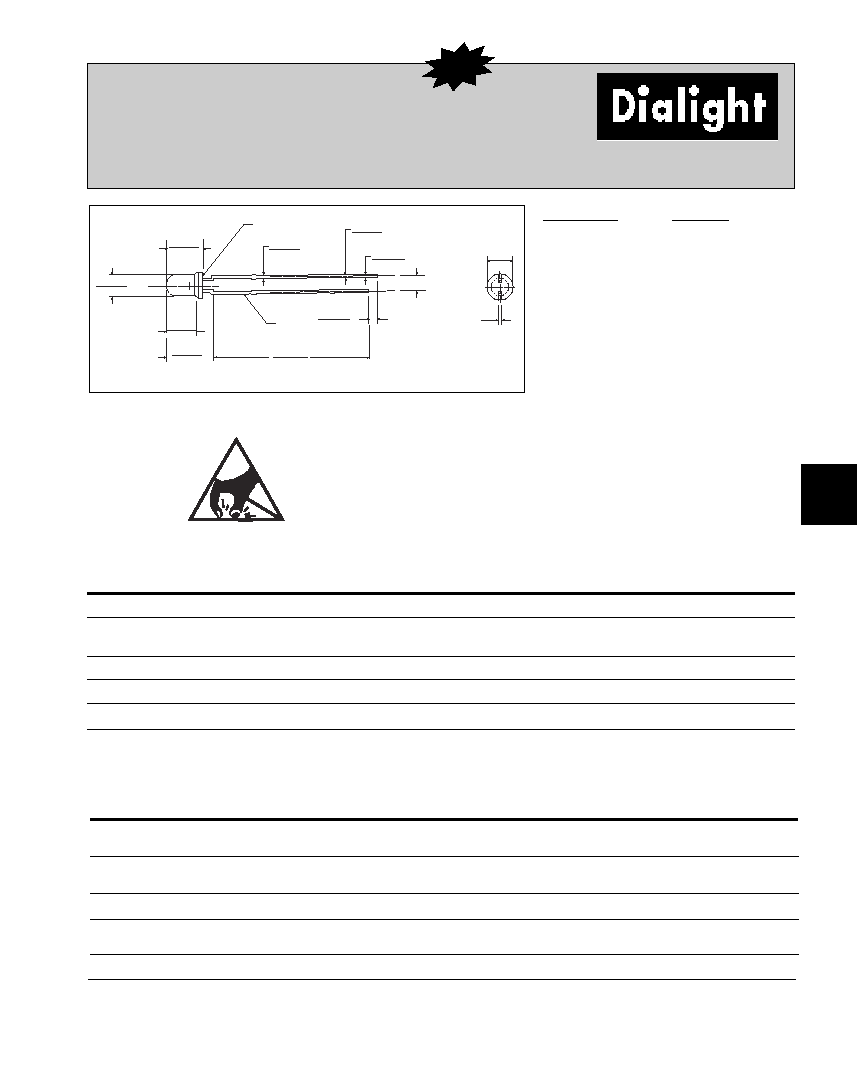
3mm Discrete LED
Tinted, Diffused
521-9831
3.4 [.134]
3.1 [.122]
0.6 [.024]
0.4 [.016]
¯
2.9 [.114]
2.7 [.106]
4.8 [.189]
4.4 [.173]
3.7 [.145]
3.5 [.138]
6.1 [.240]
5.7 [.224]
29 [1.142]
27 [1.063]
1.8 [.071]
1.2 [.047]
CATHODE
2.54 [.100]
0.6 [.024]
0.4 [.016]
0.7 [.028]
0.4 [.016]
4.8 [.189]
4.4 [.173]
SURFACE NOT FLAT
PART NO.
COLOR
521-9831
Blue
≥
Blue
ABSOLUTE MAXIMUM RATINGS
(TA=25∞C)
-9831
Power Dissipation (mW)
100
Forward Current (mA)
20
Derating (mA/∞C)
From 55∞C
.44
Operating Temperature (∞C)
-40/+100
Storage Temperature (∞C)
-40/+100
Soldering Temperature
260∞C, 5 seconds, 1.6 mm from case
Blue
OPERATING CHARACTERISTICS
(TA=25∞C)
-9831
Luminous Intensity (mcd)
Min.
6.3
IF=10mA
Typical
12
Peak Wavelength (nm)
Typical
428
Peak
Viewing Angle (2
Ω)
Typical
70∞
Forward Voltage (V)
Typical
3.5
IF=10mA
Max.
4.2
Reverse Voltage (V) IR=10µA
Min.
3
Dimensions in mm [inches]
is the off axis angle at which the luminous intensity is half the axial luminous intensity
Solder Adherence per MIL-STD-202E, Method 208C
MOUNTING CLIP: 515-0006
located on page 4-65
ATTENTION
OBSERVE PRECAUTIONS
FOR HANDLING
ELECTROSTATIC
SENSITIVE
DEVICES
≥
NEW
4-58
Dialight Corporation ∑ 1501 Route 34 South ∑ Farmingdale, NJ 07727 ∑ TEL: (732) 919-3119 ∑ FAX: (732) 751-5778 ∑www.dialight.com
Green
Yellow
Red
Orange
Red
ABSOLUTE MAXIMUM RATINGS
(T
A
=25∞C)
-9210
-9211
-9216
-9498
-9636
Power Dissipation (mW)
100
60
100
135
100
Forward Current (mA)
30
20
30
25
40
Derating (mA/∞C)
From 50∞C
1
from 25∞C
.4
.25
.4
.5
.5
1
Operating Temperature (∞C)
-55/+100
-55/+100
-55/+100
-55/+100
-55/+100
Storage Temperature (∞C)
-55/+100
-55/+100
-55/+100
-55/+100
-55/+100
Soldering Temperature
260∞C, 5 seconds, 1.6 mm from body
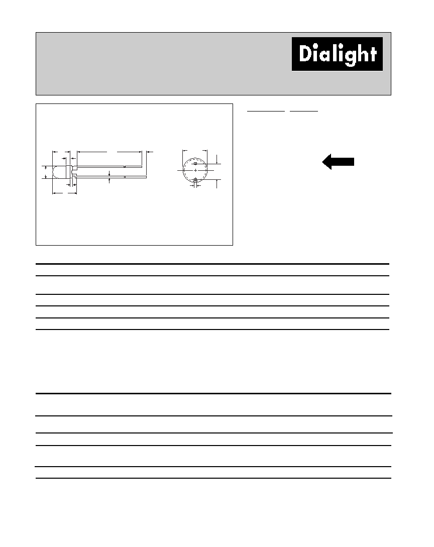
3mm Discrete LED
High Efficiency
Diffused
521-9210, -9211, -9216, -9498, -9636
4.45
[.175]
1.02
[.040]
3.00
[.118]
1.50
[.059]
MAX
6.00
[.236]
25.4
[1.0] MIN
1.02
[.040]
MIN
.45
[.016 ]
.40
[.016]
2.54
[.100]
3.30
[.13]
PART NO. COLOR
521-9210
Green
521-9211
Yellow
521-9216
Red
521-9498
Orange
521-9636
Red
Green
Yellow
Red
Orange
Red
OPERATING CHARACTERISTICS
(T
A
=25∞C)
-9210
-9211
-9216
-9498
-9636
Luminous Intensity (mcd)
Min.
4.7
7.4
7.4
3.4
8.7
1
IF=10mA
1
IF=20mA
Typical
12.6
10
10
7
48
1
Peak Wavelength (nm)
Typical
565
585
635
600
660
Peak
Viewing Angle (2
Ω
)
Typical
60∞
60∞
60∞
60∞
60∞
Forward Voltage (V)
Typical
2.1
1
2.1
1
2
1
2.2
1.8
1
IF=10mA
1
IF=20mA
Max.
2.8
1
2.8
1
2.8
1
3
2.4
1
Reverse Voltage (V), IR=100µA
Max.
5
5
5
5
4
Dimensions in mm [inches]
is the off axis angle at which the luminous intensity is half the axial luminous intensity
Solder Adherence per MIL-STD-202E, Method 208C
MOUNTING CLIP: 515-0006
located on page 4-65
short lead cathode all colors except 521-9636 Red.
For 521-9636 Red, short lead is anode.
NEW