DIONICS, INC.
Phone: (516) 997-7474
65 Rushmore Street Fax: (516) 997-7479
Westbury, NY 11590 Website: www.dionics-usa.com
DI-300 DI-302
LEVEL-SHIFTED GAS DISCHARGE DISPLAY SEGMENT DRIVER
General Description:
The DIONICS DI-300 and DI-302 are designed to drive gas discharge
digital display devices from signals developed in MOS or TTL circuitry.
Each output constitutes a switched constant current sink with a
compliance of up to 100V. This output level can absorb large fluctuation
of supply voltage. The signal is boosted in level by up to 200V (DI-300)
or 125V (DI-302). This eases interfacing between logic circuitry and
display, thus reduces costs.
Features:
�
Monolithic Silicon Dielectrically Isolated Integrated Circuit
�
Programmable Constant Current Output
�
Current Output Range: 0.1 - 2.5mA
�
200V (DI-300) or 125V (DI-302) Operation
�
Plastic 18-Pin DIP Package
�
Level Shifted For Ease Of Use
�
MOS and TTL Compatibility
�
Eight-Channel Operation
�
Pin For Pin Replacement For
Sprague UDN 7183A, UDN 7184A or UDN 7186A
Package Layout:
0.100
0.900
0.185
DIONICS INC.
DI-302
0.020
0.025
0.070
0.250
08/2002
Circuit Schematic (Each Section)
V -
A
Output
Input
13
Out7
In6
9
8
18
In1
Out4
11
In2
12
In4
1
3
7
5
In7
Out8
16
In8
4
Pin Connections
A
Out6
2
10
Out2
14
15
In5
6
In3
V -
Out5
Out1
17
Out3
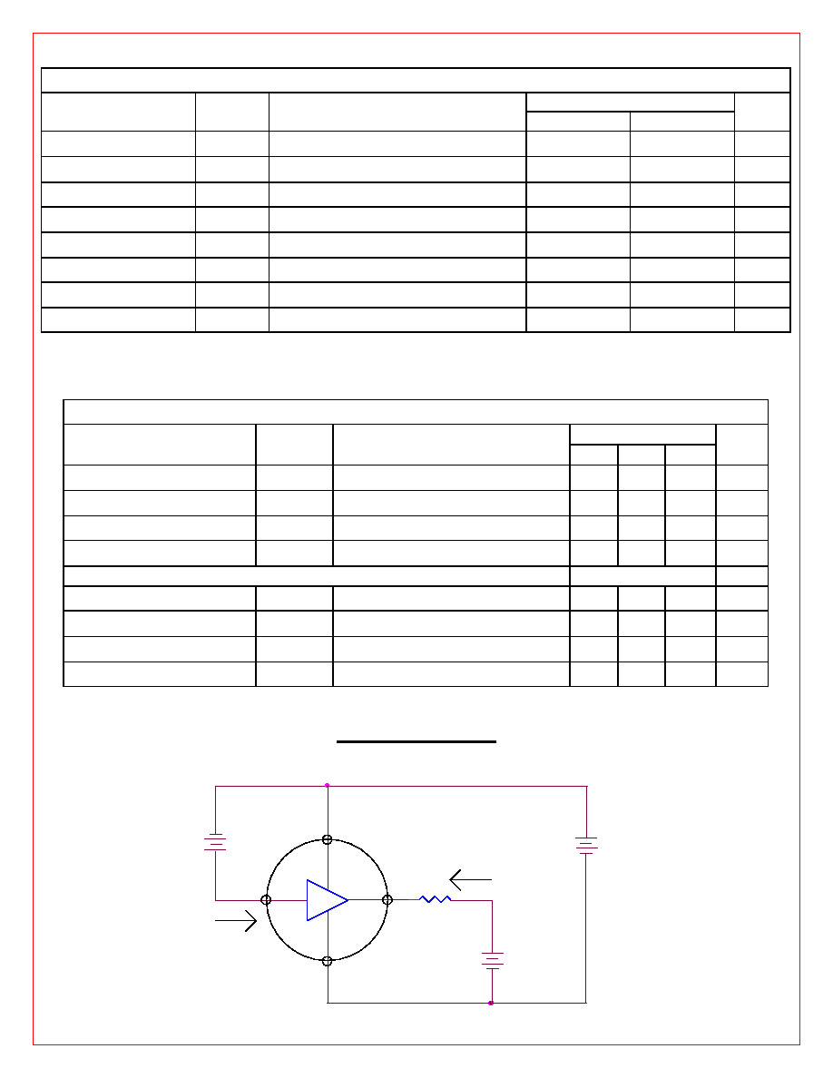
Absolute Maximum Rating (Ta = 25
0
C)
Limits
Characteristic
Symbol
Notes
DI-300
DI-302
Units
Supply Voltage
V -
Measured With Respect to Terminal "A"
-200
-125
V
Input Voltage
V
in
Measured With Respect to Other Terminal
�
20
�
20
V
Input Voltage
V
IA
Measured With Respect to Terminal "A"
20
20
V
Output Voltage
V
o
Measured With Respect to V �
100
100
V
Output Current
I
o
2.5
2.5
mA
Power Dissipation
P
D
Above 25
0
C Ambient, Derate at 8 mW /
0
C
800
800
mW
Storage Temp.
T
s
-55 to +125 -55 to +125
0
C
Operating Temp.*
T
o
0 to +70
0 to +70
0
C
* Ceramic (-20
0
C to +85
0
C)
Electrical Characteristics (Ta = 25
0
C)
DI-302
Parameter
Symbol
Conditions
Min. Typ. Max.
Units
Output Saturation Voltage V
o
(SAT)
I
o
= 1mA; V
s
= 100V
-
15
-
V
Output Leakage Current
I
o
(OFF) V
s
= 125V; V
o
= 100V; V
IA
= 0V
-
1
10
�A
Output Current Match
I
o
/ I
o
V
s
= 100V; V
o
= 60V; V
IA
= 1.2V
-
�
10
�
20
%
Output Current
I
o
(ON) V
s
= 100V; V
o
= 60V; V
IA
= 1.2V 0.5 0.85 1.2
mA
DI-300
Output Saturation Voltage V
o
(SAT)
I
o
= 1mA; V
s
= 100V
-
15
-
V
Output Leakage Current
I
o
(OFF) V
s
= 200V; V
o
= 100V; V
IA
= 0V
-
1
10
�A
Output Current Match
I
o
/ I
o
V
s
= 200V; V
o
= 60V; V
IA
= 2V
-
10
20
%
Output Current
I
o
(ON)
V
s
= 200V; V
o
= 60V; V
IA
= 2V
0.5 0.85 2.5
mA
Simplified Test Circuit
Ii
Io
+
A
+
+
Vs
V o
Via
V -
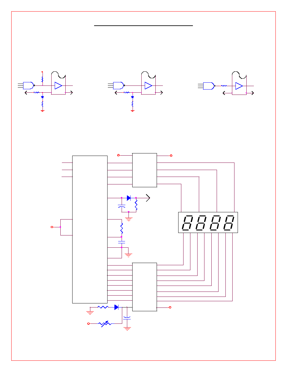
DI-302 Typical Application
These diagrams depict typical methods for setting output (Cathode) current levels. In some cases, resistor values
should be varied to adjust output current to a proper level for the particular display device used
TTL Interface
+5V
(Vcc)
V
DI-302
+5V
-100V
A
MOS Interface
DI-302
-100V
A
-15V
(Vdd)
V
MOS Interface
A
DI-302
-15V
(Vdd)
-100V
V
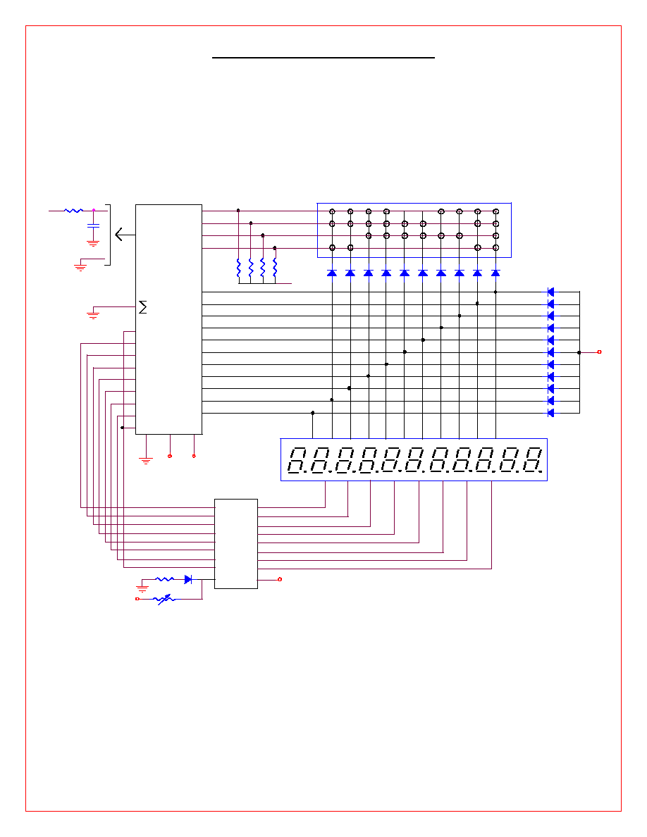
1
1
Se
22
Display Intensity
21
3.9K
-14 V
DIONICS
DI-302
CATHODE
DRIVER
3
Sd
1
20
0.01
4
Sc
D3
To
Setting
Circuit
19
5
Sb
D4
Vdd
15
Vss
7
Sa
3
CT 7001
CLOCK /
CALENDAR
16
Spm
60 Hz
10
D4
4
27
18
Sg
9
D3
DIONICS
DI-502
ANODE
DRIVER
BURROUGHS
CD-4073-GM
Sf
-14 V
8
D2
-100 V
18
Se
5
24
7
D1
17
Sd
11
IN3
6
16
Sc
10
IN2
150pF
5
+100 V
15
8
Sb
9
IN1
4
Spm
-14V
14
10
Sa
8
D1
Sg
13
11
17
23
D2
1.5K
3
27K
12
12
25
10 uF
2
11
14
Sf
26
+
14