1
) Valid for one branch ≠ G¸ltig f¸r einen Br¸ckenzweig
2
) Valid, if leads are kept at ambient temperature at a distance of 10 mm from case
G¸ltig, wenn die Anschlufldr‰hte in 10 mm Abstand vom Geh‰use auf Umgebungstemperatur gehalten werden
1
18.02.2003
KBU 12A ... KBU 12M
Silicon-Bridge Rectifiers
Silizium-Br¸ckengleichrichter
Nominal current ≠ Nennstrom
12 A
Alternating input voltage
35...700 V
Eingangswechselspannung
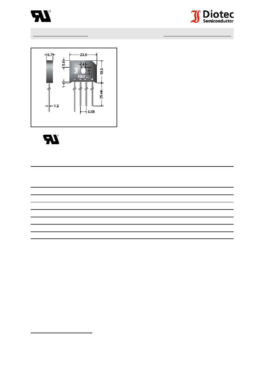
Plastic case
23.5 x 5.7 x 19.3 [mm]
Kunststoffgeh‰use
Weight approx. ≠ Gewicht ca.
8 g
Plastic material has UL classification 94V-0
Geh‰usematerial UL94V-0 klassifiziert
Dimensions / Mafle in mm
Standard packaging: bulk
see page 22
Standard Lieferform: lose im Karton
s. Seite 22
Recognized Product ≠ Underwriters Laboratories Inc.Æ File E175067
Anerkanntes Produkt ≠ Underwriters Laboratories Inc.Æ Nr. E175067
Maximum ratings
Grenzwerte
Type
Typ
max. alternating input voltage
max. Eingangswechselspannung
V
VRMS
[V]
Repetitive peak reverse voltage
Periodische Spitzensperrspannung
V
RRM
[V]
1
)
KBU 12A
35
50
KBU 12B
70
100
KBU 12D
140
200
KBU 12G
280
400
KBU 12J
420
600
KBU 12K
560
800
KBU 12M
700
1000
Repetitive peak fwd. current ≠ Period. Spitzenstrom
f > 15 Hz
I
FRM
60 A
2
)
Peak forward surge current, 60 Hz half sine-wave
T
A
= 25
/
C
I
FSM
300 A
Stoflstrom f¸r eine 60 Hz Sinus-Halbwelle
Rating for fusing ≠ Grenzlastintegral, t < 10 ms
T
A
= 25
/
C
i
2
t
375 A
2
s
Operating junction temperature ≠ Sperrschichttemperatur
T
j
≠ 50...+150
/
C
Storage temperature ≠ Lagerungstemperatur
T
S
≠ 50...+150
/
C
Admissible torque for mounting
M 4
9 ± 10% lb.in.
Zul‰ssiges Anzugsdrehmoment
1 ± 10% Nm
1
) Valid for one branch ≠ G¸ltig f¸r einen Br¸ckenzweig
2
F:\Data\WP\DatBlatt\Einzelbl‰tter\kbu12a-12mul.wpd
KBU 12A ... KBU 12M
Characteristics
Kennwerte
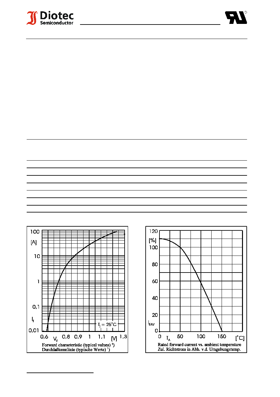
Max. fwd. current without cooling fin
T
A
= 50
/
C
R-load
I
FAV
8.4 A
Dauergrenzstrom ohne K¸hlblech
C-load
I
FAV
7.4 A
Max. current with cooling fin 300 cm
2
T
A
= 50
/
C
R-load
I
FAV
12.0 A
Dauergrenzstrom mit K¸hlblech 300 cm
2
C-load
I
FAV
9.6 A
Forward voltage ≠ Durchlaflspannung
T
j
= 25
/
C
I
F
= 12 A
V
F
< 1.0 V
1
)
Leakage current ≠ Sperrstrom
T
j
= 25
/
C
V
R
= V
RRM
I
R
< 10
:
A
Thermal resistance junction to case
R
thC
< 2.7 K/W
W‰rmewiderstand Sperrschicht ≠ Geh‰use
Type
Typ
Max. admissible load capacitor
Max. zul‰ssiger Ladekondensator
C
L
[
:
F]
Min. required protective resistor
Min. erforderl. Schutzwiderstand
R
t
[
S
]
KBU 12A
20000
0.2
KBU 12B
10000
0.4
KBU 12D
5000
0.8
KBU 12G
2500
1.6
KBU 12J
1500
2.4
KBU 12K
1000
3.2
KBU 12M
800
4.0