
RVF
15
Storage Temperature Range, T
STG
A
0.1
Max. DC Reverse Current @ PRV and 100
o
C, I
R
-55 to +150
o
C
o
C
ELECTRICAL CHARACTERISTICS(at T
A
=25 C Unless Otherwise Specified)
FAST RECOVERY - HIGH VOLTAGE
HIGH CURRENT SILICON RECTIFIERS
-55 to +150
o
C
o
C
A
Max. Reverse Recovery Time , T
(Fig.4)
Amps
Ambient Operating Temperature Range,T
A
50
Forward Voltage Repetitive Peak,I
FRM
Max.One-Half Cycle Surge Current, I
FM
(Surge )@ 60Hz
Amps
2
150 nanoseconds
Max. DC Reverse Current @ PRV and 25
o
C, I
R
EDI reserves the right to change these specifications at any time without notice.
MATCHED SILICON RECTIFIER ELEMENTS
DIFFUSED SILICON JUNCTIONS
PRV 5,000 TO 40,000 VOLTS
AVALANCHE CHARACTERISTICS
LOW LEAKAGE
EDI Type No.
Peak
Reverse Voltage
PRV (V olts)
Average Rectified
Current
@55
o
C@100
o
C
Amps
@25
o
C
I
F
=0.5 ADC
(Volts)
Length L
Fig.3
Inches MM
RVF5
5,000
0.50
0.33
9
1.25
31.75
RVF8
8,000
0.50
0.33
12
1.75
44.45
RVF10
10,000
0.33
15
2.00
50.80
RVF12.5
12,500
0.50
0.33
20
2.50
63.50
RVF15
15,000
0.50
0.33
23
3.00
76.20
RVF20
20,000
0.40
0.27
30
4.00
101.60
RVF25
25,000
0.40
0.27
38
4.50
114.30
RVF30
30,000
0.40
0.27
45
5.50
139.70
RVF40
40,000
0.40
0.27
60
7.00
177.80
0.50
rr
Max. Fwd Voltage
C
500
0
25
50
75
100
125
150
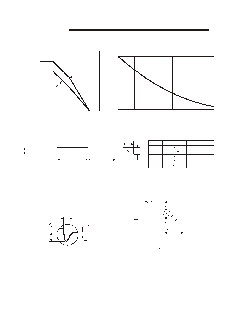
FIG.1
OUTPUT CURRENT vs AMBIENT TEMPERATURE
FIG.2
NON-REPETITIVE SURGE CURRENT RATINGS
RVF
FIG.3
PACKAGE STYLE
21 GRAY OAKS AVENUE * YONKERS. NEW YORK 10710 914-965-4400 * FAX 914-965-5531 * 1-800-678-0828
ELECTRONIC DEVICES, INC.
DESIGNERS AND MANUFACTURERS OF SOLID STATE DEVICES SINCE 1951.
AMBIENT TEMP
O
( C )
A
A
V
G
.
R
E
C
T
I
F
I
E
D
D
.
C
.
C
U
R
R
E
N
T
M
I
L
L
A
M
P
E
R
E
S
E
e-mail:sales@edidiodes.com
W
website: http://www.edidiodes.com
*
_
+
L B
TEST CIRCUIT
FIG.4
TYPICAL REVERSE RECOVERY WAVEFORM
PULSE
GENERATOR
D.U.T.
SCOPE
R
2
1 OHM
R1
50 OHM
+
-
175
400
300
200
100
600
E
D
LTR
A
B
C
D
E
INCHES
MILLIMETERS
.051 DIA.
+
_ .03
+
_ . 7 6
1.30 DIA.
0.31 MAX.
0.76 MAX.
2.0 MIN.
19.30 MAX.
7.9 MAX.
50.8 MIN.
Prior to the manufacture of these assemblies, the individual silicon junction is measured for
maximum recovery time in the test circuit shown.
RVF 5-15
RVF 20-40
100
75
50
25
0
1
2
3
4
5
6
7
9 10
20
30
40 50 60
8
CYCLES(60 Hz)
0.1SEC
1.0SEC
%
M
A
X
I
M
U
M
S
U
R
G
E
1.0A
0.5A
T RR
ZERO
REFERENCE
0.25A
R R
1, 2 NON-INDUCTIVE RESISTORS
PULSE GENERATOR - HEWLETT
PACKARD 214A OR EQUIV.
IKC REP.RATE, 10 SEC. PULSE WIDTH
ADJUST PULSE AMPLITUDE FOR PEAK IR
It is recommended that a proper heat sink be used on the terminals of this device between the body and the soldering point to
prevent damage form excess heat.