 | –≠–ª–µ–∫—Ç—Ä–æ–Ω–Ω—ã–π –∫–æ–º–ø–æ–Ω–µ–Ω—Ç: PGR20301 | –°–∫–∞—á–∞—Ç—å:  PDF PDF  ZIP ZIP |
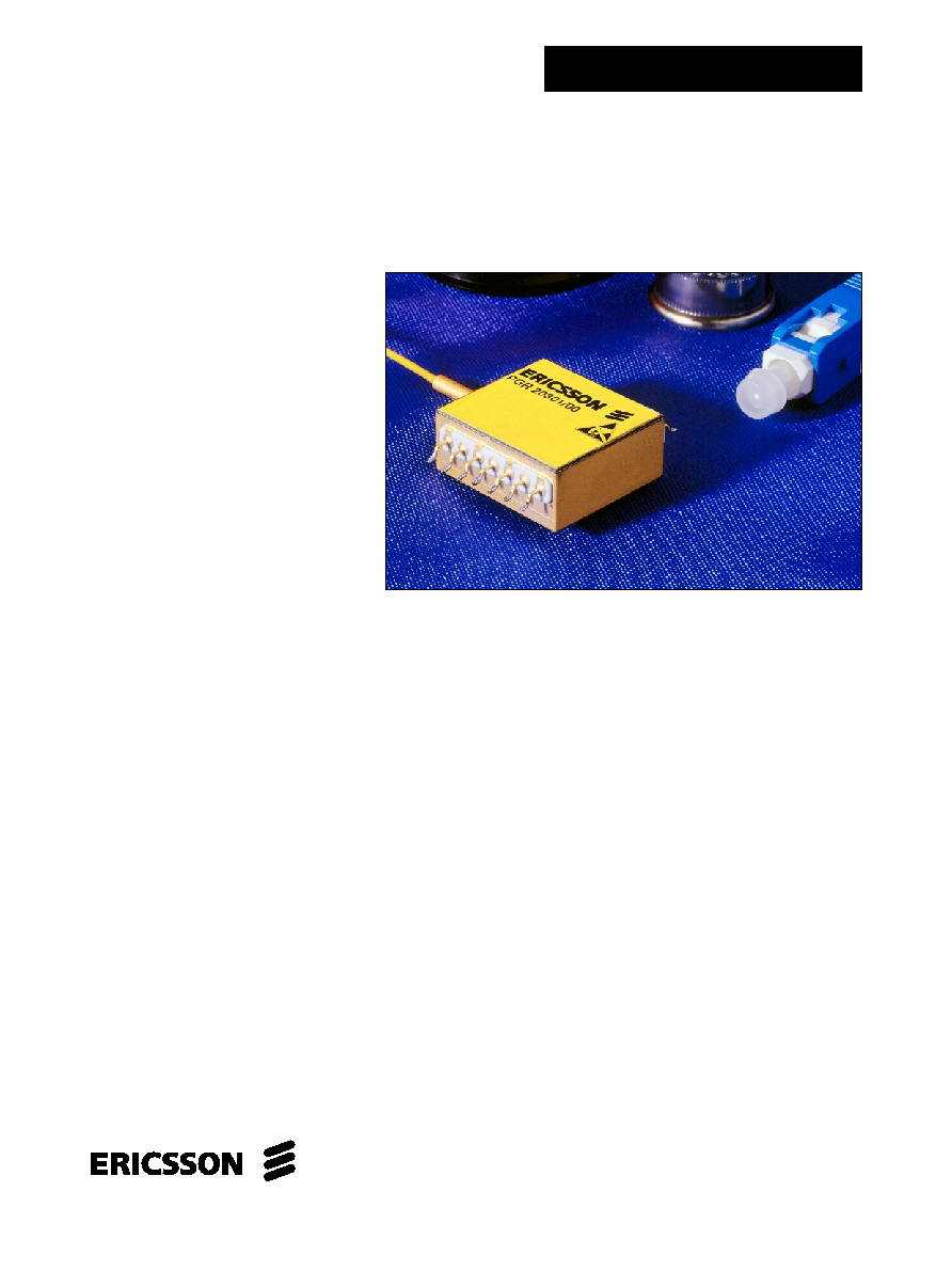
PIN Receiver Module
for 2.5 Gb/s
PGR 203 01
Description
Fiber optic receiver front-end module for STM-16 and OC-48 applications.
The module includes an InGaAs PIN Photo Diode, with a low noise GaAs
MMIC preamplifier in a 14 pin butterfly package. The single-mode fiber pigtail
is terminated with a customer specified connector. The module operates
between 1250 and 1620 nm. The electrical output is AC-coupled, single
ended and inverted i.e., light on equals logic low.
Key Features
∑ Hermetic, 14 pin butterfly package with
multisourced footprint
∑ FC/PC, SC or ST connector
∑ InGaAs PIN photo diode with low noise
GaAs MMIC preamplifier
∑ AC-coupled, single-ended data output
∑ Operates between 1250 nm and
1620 nm
∑ 1.7 GHz typical bandwidth
∑ -25 dBm typical sensitivity
∑ +0.5 dBm typical overload
Applications
∑ SDH STM-16 SH
∑ SONET OC-48 IR
∑ Digital recievers to 2.5 Gb/s
∑ Analog receivers to 1.8 GHz
1
PGR 203 01
2
Pin connection
1.
GND
2.
Vpin (+5V)
3.
GND
4.
Vss (-5.2V)
5.
GND
6.
NC
7.
GND
8.
GND
FIBER
DATA
PIN
PREAMP
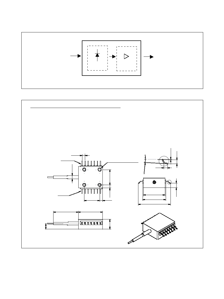
Figure 1. Block diagram
Figure 2. Pin description
A
25.4
12.7
20.2
17.9
12.7
3.9
4.5
4x M3 depth min 2.54
2.5
2.6
2.54
Lead 1
Lead 14
19.2
+0
-0.55
8
20.5
±0.3
¯
2.7
A
0.25
1.3
1.1
2
∞
- 8
∞
9.
GND
10.
Data Out (AC-coupled)
11.
GND
12.
GND
13.
Vdd (+5V)
14.
NC
Case RF (and DC) GND

PGR 203 01
3
Optical and Electrical AC Characteristics
Electrical and optical characteristics over recommended operating conditions, unless otherwise noted.
Parameter
Conditions
Symbol
Min
Typ
Max
Unit
Minimum bandwidth (-3dB)
-20dBm < Pf < -3dBm
BW
min
1.4
1.7
2.1
GHz
Bandwidth variation
-20dBm < Pf < -3dBm
1.1
1.2
BW
max
=
∑BW
min
Gain peaking
Peak
0
1
dB
Sensitivity: Pf @ BER = 1∑10
-10
2.5 Gbps NRZ,
Pr
-25
-22
dBm
PRBS 2
23
-1,
=1550 nm
Overload: Pf @ BER = 1∑10
-10
2.5 Gbps NRZ,
Pol
0
0.5
dBm
PRBS 2
23
-1,
=1550 nm
Output signal swing
-20dBm < Pf < -3dBm
V
Out
15
1000
mV
P-P
R
L
= 50
,
= 1550nm, ER ~10
AC transimpedance
R
L
= 50
, Tz = dV
Out
/l
Ph
, ave
Tz
1.8
k
Logic sense
Data out
Light "ON" = Logic "LOW"
Optical and Electrical DC Characteristics
Electrical and optical characteristics over recommended operating conditions, unless otherwise noted.
Parameter
Conditions
Symbol
Min
Typ
Max
Unit
DC Power supply current
I
dd
115
130
mA
I
ss
90
100
mA
Power consumption
P
Con
1.0
1.25
W
PIN Responsivity
= 1300 nm
R
13
0.9
A/W
= 1550 nm
R
15
1.0
A/W
Optical reflectance
s11
-27
dB
Recommended Operating Conditions
Parameter
Symbol
Min
Typ
Max
Unit
Optical wavelength
1250
1620
nm
Case temperature
T
Case
0
70
∞
C
DC Power supply voltage
V
dd
4.7
5.0
5.3
V
V
ss
-5.5
-5.2
-4.9
V
PIN bias
V
Pin
5
V
Absolute Maximum Ratings
Parameter
Symbol
Min
Max
Unit
DC Power supply voltage
V
dd
-0.5
6.5
V
V
ss
-7.0
0.5
V
Storage temperature
T
Stg
-40
85
∞
C
CAUTION: Stresses outside those listed in "Absolute Maximum Ratings" may cause permanent damage to the device.
This is a stress only rating and operation of the device at these or any other conditions above those indicated in the
operational sections of this specification is not implied.

PGR 203 01
4
Ericsson Microelectronics AB
SE-164 81 Kista, Sweden
Telephone: +46 8 757 50 00
www.ericsson.com/microelectronics
For local sales contacts, please refer to our website
or call: Int + 46 8 757 47 00, Fax: +46 8 757 47 76
1522-PGR 203 01 Rev. D
© Ericsson Microelectronics AB, August 2000
Information given in this data sheet is believed to be accurate and
reliable. However no responsibility is assumed for the consequences of
its use nor for any infringement of patents or other rights of third
parties which may result from its use. No license is granted by
implication or otherwise under any patent or patent rights of Ericsson
Microelectronics. These products are sold only according to Ericsson
Microelectronics' general conditions of sale, unless otherwise
confirmed in writing.
Product specifications subject to change without
notice.
Handling Precautions
This device may be damaged as a result of electrostatic
discharge (ESD). Take proper precautions during both han-
dling and testing. This typically includes grounded wrist
wraps, workbenches and floor mats in ESD controlled areas.
Semiconductor devices may be damaged by current surges,
use appropriate transient protection.
Quality Assurance
Ericsson Microelectronics commitment to quality has been
proven through a decade of semiconductor device produc-
tion and has been confirmed to ISO 9001. Opto product
qualification is made according to the intention of applicable
Telcordia standards.
Connector Options
FC/PC
SC
ST
(Other connectors available on request)