
X
T
April 1999
Intel and Pentium are registered trademarks of Intel Corporation. I
2
C is a licensed trademark of Philips Electronics, N.V. American Microsystems, Inc. reserves the right to change the detail specifica-
tions as may be required to permit improvements in the design of its products.
4.5.99
)6)6)6)6
/RZ6NHZ &ORFN )DQRXW %XIIHU ,&V
,62
1.0 Features
�
Generates up to eighteen low-skew, non-inverting
clocks from one clock input
�
Supports up to four SDRAM DIMMs
�
Uses either I
2
C
TM
-bus or SMBus serial interface with
Read and Write capability for individual clock output
control
�
Output enable pin tristates all clock outputs to facili-
tate board testing
�
Clock outputs skew-matched to less than 250ps
�
Less than 5ns propagation delay
�
Output impedance: 17
at 0.5V
DD
�
Serial interface I/O meet I
2
C specifications; all other
I/O are LVTTL/LVCMOS-compatible
�
Five differerent pin configurations available:
�
FS6050: 18 clock outputs in a 48-pin SSOP
�
FS6051: 10 clock outputs in a 28-pin SOIC, SSOP
�
FS6053: 13 clock outputs in a 28-pin SOIC
�
FS6054: 14 clock outputs in a 28-pin SOIC
Figure 1: Block Diagram (FS6050)
Serial
Interface
SDRAM_(0:1)
SCL
SDA
CLK_IN
OE
FS6050
SDRAM_(2:3)
SDRAM_(4:5)
SDRAM_(6:7)
SDRAM_(8:9)
SDRAM_(10:11)
SDRAM_(12:13)
SDRAM_(14:15)
SDRAM_16
VSS_I
2
C
VDD_I
2
C
VSS
VDD
VSS
VDD
VSS
VDD
VSS
VDD
VSS
VDD
VSS
VDD
VSS
VDD
VSS
VDD
VSS
VDD
SDRAM_17
VSS
VDD
18
2.0 Description
The FS6050 family of CMOS clock fanout buffer ICs are
designed for high-speed motherboard applications, such
as Intel Pentium
�
II PC100-based systems with 100MHz
SDRAM.
Up to eighteen buffered, non-inverting clock outputs are
fanned-out from one clock input. Individual clocks are
skew matched to less than 250ps at 100MHz. Multiple
power and ground supplies reduce the effects of supply
noise on device performance.
Under I
2
C-bus control, individual clock outputs may be
turned on or off. An active-low output enable is available
to force all the clock outputs to a tristate level for system
testing.
Figure 2: Pin Configuration (FS6050)
1
48
2
3
4
5
6
7
8
47
46
45
44
43
42
41
(
r
es
er
v
ed)
(
r
es
er
v
ed)
VD
D
S
DRA
M_
0
S
DRA
M_
1
VSS
VD
D
S
DRA
M_
2
VS
S
SD
R
A
M
_14
SD
R
A
M
_15
(
r
es
er
v
e
d)
VD
D
(
r
es
er
v
e
d)
9
10
11
12
13
14
15
16
S
DRA
M_
3
VSS
CL
K
_
I
N
VD
D
S
DRA
M_
4
S
DRA
M_
5
VSS
VD
D
17
18
19
20
21
22
23
S
DRA
M_
6
S
DRA
M_
7
VSS
VD
D
S
DRA
M_
1
6
VSS
V
DD_
I
2
C
40
39
38
37
36
35
34
33
SD
R
A
M
_10
SD
R
A
M
_11
VD
D
OE
SD
R
A
M
_13
SD
R
A
M
_12
VS
S
VD
D
32
31
30
29
28
27
26
VS
S_I
2
C
VS
S
SD
R
A
M
_17
VD
D
SD
R
A
M
_
9
SD
R
A
M
_
8
VS
S
24
SD
A
25
SC
L
VD
D
VS
S
FS6050
48-pin SSOP
Figure 3: Pin Configuration (FS6051)
1
2
3
4
5
6
7
8
VD
D
SD
R
A
M
_
0
SD
R
A
M
_
1
VSS
VD
D
SD
R
A
M
_
2
VS
S
S
DRA
M
_
1
4
S
DRA
M
_
1
5
VD
D
9
10
11
12
13
14
15
16
SD
R
A
M
_
3
VSS
CL
K
_
I
N
VD
D
17
18
19
20
21
22
23
S
DRA
M_
1
6
VSS
V
DD_
I
2
C
VD
D
OE
S
DRA
M
_
1
3
S
DRA
M
_
1
2
VS
S
VD
D
28
27
26
V
SS_I
2
C
VS
S
S
DRA
M
_
1
7
24
SD
A
25
SC
L
FS6051
28-pin SOIC, SSOP
Additional pin configurations are noted on Page 2.

X
T
April 1999
4.5.99
2
)6)6)6)6
/RZ6NHZ &ORFN )DQRXW %XIIHU ,&V
,62
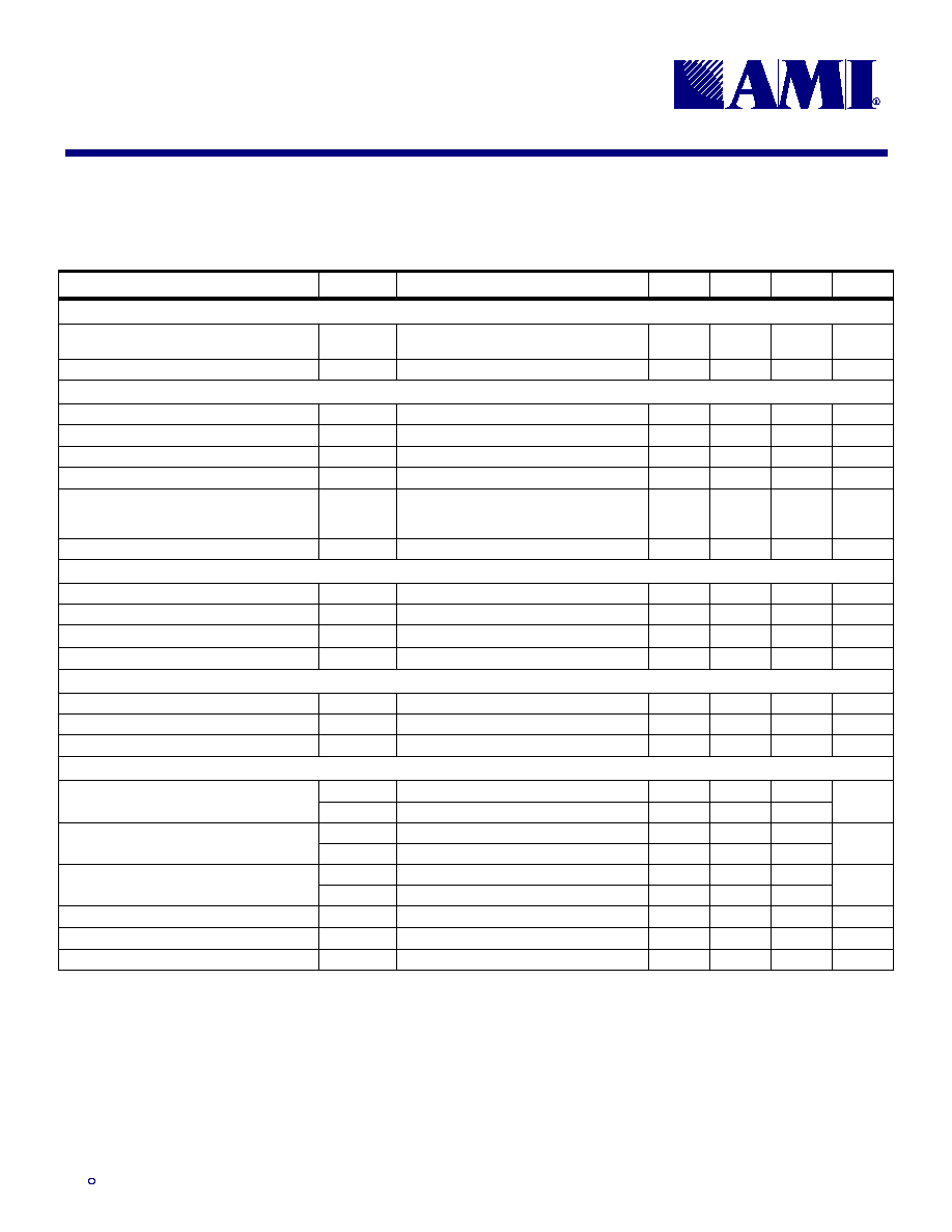
Table 1: Pin Descriptions
Key: AI = Analog Input; AO = Analog Output; DI = Digital Input; DI
U
= Input with Internal Pull-Up; DI
D
= Input with Internal Pull-Down; DIO = Digital Input/Output; DI-3 = Three-Level Digital Input,
DO = Digital Output; P = Power/Ground; # = Active Low pin
PIN (FS6050)
PIN (FS6051)
PIN (FS6053)
PIN (FS6054)
TYPE
NAME
DESCRIPTION
11
9
9
9
DI
CLK_IN
Clock input for SDRAM clock outputs
25
15
15
15
DI
U
SCL
Serial clock input
24
14
14
14
DI
U
O
SDA
Serial data input/output
4
2
2
2
DO
SDRAM_0
5
3
3
3
DO
SDRAM_1
8
6
6
6
DO
SDRAM_2
9
7
7
7
DO
SDRAM_3
13
-
-
-
DO
SDRAM_4
14
-
-
-
DO
SDRAM_5
17
-
10
10
DO
SDRAM_6
18
-
11
11
DO
SDRAM_7
SDRAM clock outputs (Byte 0)
31
-
18
18
DO
SDRAM_8
32
-
19
19
DO
SDRAM_9
35
-
-
-
DO
SDRAM_10
36
-
-
-
DO
SDRAM_11
40
22
22
22
DO
SDRAM_12
41
23
23
23
DO
SDRAM_13
44
26
26
26
DO
SDRAM_14
45
27
27
27
DO
SDRAM_15
SDRAM clock outputs (Byte 1)
21
11
12
12
DO
SDRAM_16
28
18
-
17
DO
SDRAM_17
SDRAM feedback clock outputs (Byte 2)
38
20
-
20
DI
U
OE
Output enable tristates all clock outputs when low
3, 7, 12, 16,
20, 29, 33, 37,
42, 46
1, 5, 10, 19,
24, 28
1, 5, 20, 24,
28
1, 5, 24, 28
P
VDD
3.3V � 5% power supply for SDRAM clock buffers
23
13
13
13
P
VDD_I
2
C
3.3V � 5% power supply for serial communications
6, 10, 15, 19,
22, 27, 30, 34,
39, 43
4, 8, 12, 17,
21, 25
4, 8, 17, 21,
25
4, 8, 21, 25
P
VSS
Ground for SDRAM clock buffers
26
16
16
16
P
VSS_I
2
C
Ground for serial communications
1, 2, 47, 48
-
-
-
-
(reserved)
Reserved
Figure 4: Pin Configuration (FS6053)
1
2
3
4
5
6
7
8
VD
D
SD
RAM
_
0
SD
RAM
_
1
VSS
VD
D
SD
RAM
_
2
VSS
S
DRA
M
_
1
4
S
DRA
M
_
1
5
VD
D
9
10
11
12
13
14
15
16
SD
RAM
_
3
VSS
CL
K_
I
N
SD
RAM
_
6
17
18
19
20
21
22
23
SD
RAM
_
7
S
D
R
A
M_16
V
DD_
I
2
C
S
DRA
M
_
9
VD
D
S
DRA
M
_
1
3
S
DRA
M
_
1
2
VSS
VD
D
28
27
26
VSS_
I
2
C
VSS
S
DRA
M
_
8
24
SD
A
25
SC
L
FS6053
Figure 5: Pin Configuration (FS6054)
1
2
3
4
5
6
7
8
VD
D
S
DRA
M
_
0
S
DRA
M
_
1
VS
S
VD
D
S
DRA
M
_
2
VSS
SD
RAM
_
1
4
SD
RAM
_
1
5
VD
D
9
10
11
12
13
14
15
16
S
DRA
M
_
3
VS
S
CL
K
_
I
N
S
DRA
M
_
6
17
18
19
20
21
22
23
S
DRA
M
_
7
S
DRA
M
_
1
6
VD
D_
I
2
C
SD
RAM
_
9
OE
SD
RAM
_
1
3
SD
RAM
_
1
2
VSS
VD
D
28
27
26
VSS_
I
2
C
SD
RAM
_
1
7
SD
RAM
_
8
24
SD
A
25
SC
L
FS6054

X
T
April 1999
4.5.99
3
)6)6)6)6
/RZ6NHZ &ORFN )DQRXW %XIIHU ,&V
,62
3.0 Programming
Information
Table 2: Clock Enable
CONTROL INPUTS
CLOCK OUTPUTS (MHz)
OE
SDRAM_0:17
0
tristate
1
CLK_IN
3.1
Power-Up Initialization
All outputs are enabled and active upon power-up, and all
output control register bits are initialized to one.
The outputs must be configured at power-up and are not
expected to be configured during normal operation. Inac-
tive outputs are held low and are disabled from switching.
3.1.1
Unused Outputs
Outputs that are not used in versions of this device with a
reduced pinout are still operational internally. To reduce
power dissipation and crosstalk effects from the unloaded
outputs, it is recommended that these outputs be shut off
via the Control Registers.
3.2
Register Programming
A logic-one written to a valid bit location turns on the as-
signed output clock. Likewise, a logic-zero written to a
valid bit location turns off the assigned output clock.
Any unused or reserved register bits should be cleared to
zero.
Serial bits are written to this device in the order shown in
Table 3.
Table 3: Register Summary
SERIAL BIT
DATA BYTE
CLOCK OUTPUT
0
(MSB)
SDRAM_7
1
SDRAM_6
2
SDRAM_5
3
SDRAM_4
4
SDRAM_3
5
SDRAM_2
6
Byte 0
SDRAM Control Register 0
SDRAM_1
7
(LSB)
SDRAM_0
8
(MSB)
SDRAM_15
9
SDRAM_14
10
SDRAM_13
11
SDRAM_12
12
SDRAM_11
13
SDRAM_10
14
Byte 1
SDRAM Control Register 1
SDRAM_9
15
(LSB)
SDRAM_8
16
(MSB)
SDRAM_17
17
SDRAM_16
18
Reserved
19
Reserved
20
Reserved
21
Reserved
22
Byte 2
SDRAM Control Register 2
Reserved
23
(LSB)
Reserved

X
T
April 1999
4.5.99
4
)6)6)6)6
/RZ6NHZ &ORFN )DQRXW %XIIHU ,&V
,62
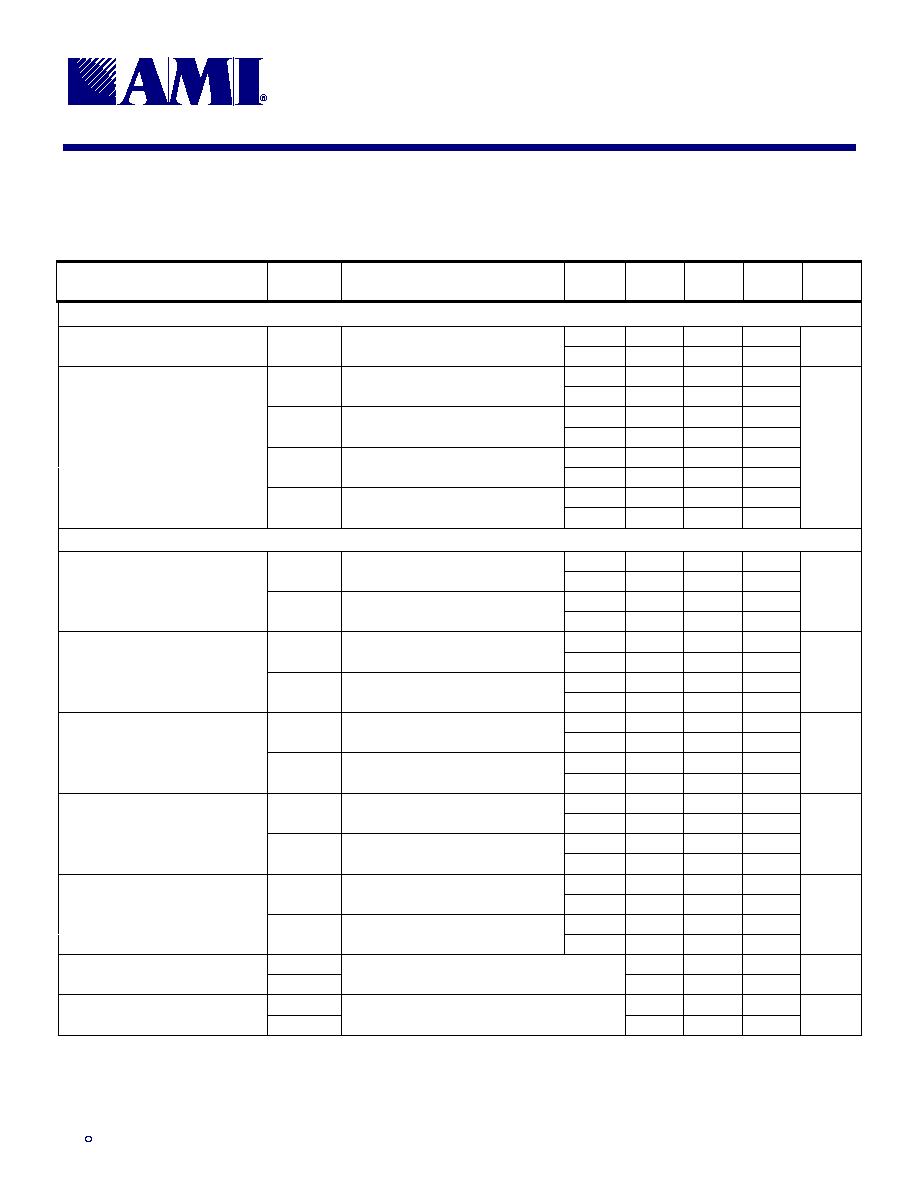
Table 4: Byte 0 - SDRAM Control Register 0
REGISTER
BIT
CLOCK
OUTPUT
DESCRIPTION
OUTPUT PIN
(FS6050)
OUTPUT PIN
(FS6051)
OUTPUT PIN
(FS6053)
OUTPUT PIN
(FS6054)
7
SDRAM_7
On (1) / Off (0)
Pin 18
-
Pin 11
Pin 11
6
SDRAM_6
On (1) / Off (0)
Pin 17
-
Pin 10
Pin 10
5
SDRAM_5
On (1) / Off (0)
Pin 14
-
-
-
4
SDRAM_4
On (1) / Off (0)
Pin 13
-
-
-
3
SDRAM_3
On (1) / Off (0)
Pin 9
Pin 7
Pin 7
Pin 7
2
SDRAM_2
On (1) / Off (0)
Pin 8
Pin 6
Pin 6
Pin 6
1
SDRAM_1
On (1) / Off (0)
Pin 5
Pin 3
Pin 3
Pin 3
0
SDRAM_0
On (1) / Off (0)
Pin 4
Pin 2
Pin 2
Pin 2
Table 5: Byte 1 - SDRAM Control Register 1
REGISTER
BIT
CLOCK
OUTPUT
DESCRIPTION
OUTPUT PIN
(FS6050)
OUTPUT PIN
(FS6051)
OUTPUT PIN
(FS6053)
OUTPUT PIN
(FS6054)
15
SDRAM_15
On (1) / Off (0)
Pin 45
Pin 27
Pin 27
Pin 27
14
SDRAM_14
On (1) / Off (0)
Pin 44
Pin 26
Pin 26
Pin 26
13
SDRAM_13
On (1) / Off (0)
Pin 41
Pin 23
Pin 23
Pin 23
12
SDRAM_12
On (1) / Off (0)
Pin 40
Pin 22
Pin 22
Pin 22
11
SDRAM_11
On (1) / Off (0)
Pin 36
-
-
-
10
SDRAM_10
On (1) / Off (0)
Pin 35
-
-
-
9
SDRAM_9
On (1) / Off (0)
Pin 32
-
Pin 19
Pin 19
8
SDRAM_8
On (1) / Off (0)
Pin 31
-
Pin 18
Pin 18
Table 6: Byte 2 - SDRAM Control Register 2
REGISTER
BIT
CLOCK
OUTPUT
DESCRIPTION
OUTPUT PIN
(FS6050)
OUTPUT PIN
(FS6051)
OUTPUT PIN
(FS6053)
OUTPUT PIN
(FS6054)
23
SDRAM_17
On (1) / Off (0)
Pin 28
Pin 18
-
Pin 17
22
SDRAM_16
On (1) / Off (0)
Pin 21
Pin 11
Pin 12
Pin 12
21
Reserved (set to 0)
-
-
-
-
20
Reserved (set to 0)
-
-
-
-
19
Reserved (set to 0)
-
-
-
-
18
Reserved (set to 0)
-
-
-
-
17
Reserved (set to 0)
-
-
-
-
16
Reserved (set to 0)
-
-
-
-

X
T
April 1999
4.5.99
5
)6)6)6)6
/RZ6NHZ &ORFN )DQRXW %XIIHU ,&V
,62
4.0 Dual Serial Interface Control
This integrated circuit is a read/write slave device that
supports both the Inter IC Bus (I
2
C-bus) and the System
Management Bus (SMBus) two-wire serial interface pro-
tocols. The unique device address that is written to the
device determines whether the part expects to receive
SMBus commands or I
2
C commands. Since SMBus is
derived from the I
2
C-bus, the protocol for both bus types
is very similar.
In general, the bus has to be controlled by a master de-
vice that generates the serial clock SCL, controls bus
access, and generates the START and STOP conditions
while the device works as a slave. Both master and slave
can operate as a transmitter or receiver, but the master
device determines which mode is activated. A device that
sends data onto the bus is defined as the transmitter, and
a device receiving data as the receiver.
Bus logic levels and timing parameters noted herein fol-
low I
2
C-bus convention. Logic levels are based on a per-
centage of VDD. A logic-one corresponds to a nominal
voltage of VDD, while a logic-zero corresponds to ground
(VSS).
4.1 Bus
Conditions
Data transfer on the bus can only be initiated when the
bus is not busy. During the data transfer, the data line
(SDA) must remain stable whenever the clock line (SCL)
is high. Changes in the data line when the clock line is
high is interpreted by the device as a START or STOP
condition. Both I
2
C-bus and SMBus protocols define the
following conditions on the bus. Refer to Figure 12: Bus
Timing Data for more information.
4.1.1 Not
Busy
Both the data (SDA) and clock (SCL) lines remain high to
indicate the bus is not busy.
4.1.2
START Data Transfer
A high to low transition of the SDA line while the SCL in-
put is high indicates a START condition. All commands to
the device must be preceded by a START condition.
4.1.3
STOP Data Transfer
A low to high transition of the SDA line while SCL is held
high indicates a STOP condition. All commands to the
device must be followed by a STOP condition.
4.1.4
Data Valid
The state of the SDA line represents valid data if the SDA
line is stable for the duration of the high period of the SCL
line after a START condition occurs. The data on the
SDA line must be changed only during the low period of
the SCL signal. There is one clock pulse per data bit.
Each data transfer is initiated by a START condition and
terminated with a STOP condition. The number of data
bytes transferred between START and STOP conditions
is determined by the master device, and can continue
indefinitely. However, data that is overwritten to the de-
vice after the data registers are filled will overflow from
the last register into the first register, then the second,
and so on, in a first-in, first-overwritten fashion.
4.1.5 Acknowledge
When addressed, the receiving device is required to gen-
erate an Acknowledge after each byte is received. The
master device must generate an extra clock pulse to co-
incide with the Acknowledge bit. The acknowledging de-
vice must pull the SDA line low during the high period of
the master acknowledge clock pulse. Setup and hold
times must be taken into account.
The master must signal an end of data to the slave by not
generating an acknowledge bit on the last byte that has
been read (clocked) out of the slave. In this case, the
slave must leave the SDA line high to allow the master to
generate a STOP condition.
4.2
Bus Operation and Commands
All programmable registers can be accessed via the bi-
directional two wire digital interface. The device accepts
the Random Register Read/Write and the Sequential
Register Read/Write I
2
C commands. The device also
supports the Block Read/Write SMBus commands.
4.2.1 I
2
C-bus and SMBus Device Addressing
After generating a START condition, the bus master
broadcasts a seven-bit device address followed by a R/W
bit. Note that every device on an I
2
C-bus or SMBus must
have a unique address to avoid bus conflicts.
For an SMBus interface, the address of the device is:
A6
A5
A4
A3
A2
A1
A0
1
1
0
1
0
0
1

X
T
April 1999
4.5.99
6
)6)6)6)6
/RZ6NHZ &ORFN )DQRXW %XIIHU ,&V
,62
For an I
2
C-bus interface, the device can support two de-
vice addresses to permit multiple devices on one I
2
C-bus.
The A2 address bit is ignored and can be set to either a
one or a zero.
Therefore, for an I
2
C-bus interface the device address is:
A6
A5
A4
A3
A2
A1
A0
1
0
1
1
X
0
0
4.2.2 I
2
C-bus: Random Register Write Procedure
Random write operations, as shown in Figure
6, allow the master to directly write to any
register. To initiate a write procedure, the R/W
bit that is transmitted after the seven-bit I
2
C
device address is a logic-low. This indicates to the ad-
dressed slave device that a register address will follow
after the slave device acknowledges its device address.
The register address is written into the slave's address
pointer. Following an acknowledge by the slave, the
master is allowed to write eight bits of data into the ad-
dressed register. A final acknowledge is returned by the
device, and the master generates a STOP condition.
If either a STOP or a repeated START condition occurs
during a Register Write, the data that has been trans-
ferred is ignored.
4.2.3 I
2
C-bus: Random Register Read Procedure
Random read operations allow the master to directly read
from any register. To perform a read procedure, as
shown in Figure 7, the R/W bit that is transmitted after the
seven-bit I
2
C address is a logic-low, as in the Register
Write procedure. This indicates to the addressed slave
device that a register address will follow after the slave
device acknowledges its device address. The register
address is then written into the slave's address pointer.
Following an acknowledge by the slave, the master gen-
erates a repeated START condition. The repeated
START terminates the write procedure, but not until after
the slave's address pointer is set. The slave address is
then resent, with the R/W bit set this time to a logic-high,
indicating to the slave that data will be read. The slave
will acknowledge the device address, and then transmits
the eight-bit word. The master does not acknowledge the
transfer but does generate a STOP condition.
4.2.4 I
2
C-bus: Sequential Register Write Procedure
Sequential write operations, as shown in Figure 8, allow
the master to write to each register in order. The register
pointer is automatically incremented after each write. This
procedure is more efficient than the Random Register
Write if several registers must be written.
To initiate a write procedure, the R/W bit that is transmit-
ted after the seven-bit I
2
C device address is a logic-low.
This indicates to the addressed slave device that a reg-
ister address will follow after the slave device acknowl-
edges its device address. The register address is written
into the slave's address pointer. Following an acknowl-
edge by the slave, the master is allowed to write data up
to the last addressed register before the register address
pointer overflows back to the beginning address. An ac-
knowledge by the device between each byte of data must
occur before the next data byte is sent.
Registers are updated every time the device sends an
acknowledge to the host. The register update does not
wait for the STOP condition to occur. Registers are
therefore updated at different times during a Sequential
Register Write.
4.2.5 I
2
C-bus: Sequential Register Read Procedure
Sequential read operations allow the master to read from
each register in order. The register pointer is automati-
cally incremented by one after each read. This proce-
dure, as shown in Figure 9, is more efficient than the
Random Register Read if several registers must be read
from.
To perform a read procedure, the R/W bit that is trans-
mitted after the seven-bit I
2
C address is a logic-low, as in
the Register Write procedure. This indicates to the ad-
dressed slave device that a register address will follow
after the slave device acknowledges its device address.
The register address is then written into the slave's ad-
dress pointer.
Following an acknowledge by the slave, the master gen-
erates a repeated START condition. The repeated
START terminates the write procedure, but not until after
the slave's address pointer is set. The slave address is
then resent, with the R/W bit set this time to a logic-high,
indicating to the slave that data will be read. The slave
will acknowledge the device address, and then transmits
all data starting with the initial addressed register. The
register address pointer will overflow if the initial register
address is larger than zero. After the last byte of data, the
master does not acknowledge the transfer but does gen-
erate a STOP condition.

X
T
April 1999
4.5.99
7
)6)6)6)6
/RZ6NHZ &ORFN )DQRXW %XIIHU ,&V
,62
Figure 6: Random Register Write Procedure (I
2
C-bus)
A
A
DATA
W A
From bus host
to device
S
REGISTER ADDRESS
P
From device
to bus host
DEVICE ADDRESS
Register Address
Acknowledge
STOP Condition
Data
Acknowledge
Acknowledge
START
Command
WRITE Command
7-bit Receive
Device Address
Figure 7: Random Register Read Procedure (I
2
C-bus)
A
R
A
A
A
W
S
REGISTER ADDRESS
P
S
DEVICE ADDRESS
START
Command
WRITE Command
Acknowledge
Register Address
Acknowledge
READ Command
Acknowledge
Data
NO Acknowledge
STOP Condition
From bus host
to device
From device
to bus host
7-bit Receive
Device Address
7-bit Receive
Device Address
DEVICE ADDRESS
DATA
Repeat START
Figure 8: Sequential Register Write Procedure (I
2
C-bus)
A
A
A
W
S
P
START
Command
WRITE Command
Acknowledge
Register Address
Acknowledge
Data
Data
Acknowledge
Data
STOP Command
Acknowledge
Acknowledge
From bus host
to device
From device
to bus host
7-bit Receive
Device Address
DEVICE ADDRESS
A
A
REGISTER ADDRESS
DATA
DATA
DATA
Figure 9: Sequential Register Read Procedure (I
2
C-bus)
A
W
S
START
Command
WRITE Command
Acknowledge
Register Address
Acknowledge
Data
Acknowledge
Data
STOP Command
Acknowledge
READ Command
NO Acknowledge
From bus host
to device
From device
to bus host
7-bit Receive
Device Address
7-bit Receive
Device Address
DEVICE ADDRESS
A
A
REGISTER ADDRESS
A
R
A P
S
DEVICE ADDRESS
DATA
DATA
Repeat START

X
T
April 1999
4.5.99
8
)6)6)6)6
/RZ6NHZ &ORFN )DQRXW %XIIHU ,&V
,62
SMBus
4.2.6
SMBus: Block Write
The Block Write command permits the
master to write several bytes of data to
sequential registers, starting by default at Register 0. The
Block Write command, as noted in Figure 10, begins with
the seven-bit SMBus device address followed by a logic-
low R/W bit to begin a Write command. Following an ac-
knowledge of the SMBus address and R/W bit by the
slave device, a command code is written.
It is defined
that all eight bits of the command code must be zero (0).
After the command code of zero and an acknowledge,
the host then issues a byte count that describes the
number of data bytes to be written. According to SMBus
convention, the byte count should be a value between 0
and 32; however this slave device ignores the byte count
value.
Following an acknowledge of the byte count, data bytes
may be written starting with Register 0 and incrementing
sequentially. An acknowledge by the device between
each byte of data must occur before the next data byte is
sent.
4.2.7
SMBus: Block Read
The Block Read command, shown in Figure 11, permits
the master to read several bytes of data from sequential
registers, starting by default at Register 0. To perform a
Block Read procedure the R/W bit that is transmitted af-
ter the seven-bit SMBus address is a logic-low, as in the
Block Write procedure. The write bit resets the register
address pointer to zero. Following an acknowledge of the
SMBus address and R/W bit by the slave device, a com-
mand code is written.
It is defined that all eight bits of the
command code must be zero (0).
Following an acknowledge by the slave, the master gen-
erates a repeated START condition. The repeated
START terminates the write procedure, but not until after
the slave's address pointer is set. The slave SMBus ad-
dress is then resent, with the R/W bit set this time to a
logic-high, indicating to the slave that data will be read.
The slave will acknowledge the device address, and then
will expect a byte count value (which will be ignored).
Following the byte count value, the device will take com-
mand of the bus and will transmit all the data beginning
with Register 0. After the last byte of data, the master
does not acknowledge the transfer but does generate a
STOP condition.
If the master does not want to receive all the data, the
master can not acknowledge the last data byte and then
can issue a STOP condition of the next clock.
Figure 10: Block Write (SMBus)
A
A
A
DATA BYTE 1
WRITE Command
Acknowledge
Command Code
Acknowledge
Data
Acknowledge
Data
STOP Command
DATA BYTE N
Acknowledge
Byte Count
Acknowledge
START
Command
From bus host
to device
From device
to bus host
7-bit Receive
Device Address
W
S
DEVICE ADDRESS
A
A
BYTE COUNT = N
P
Figure 11: Block Read (SMBus)
A
W
A
R
A
A
START
Command
WRITE Command
Acknowledge
Command Code
Acknowledge
Data
Acknowledge
Data
STOP Command
Acknowledge
Byte Count
NO Acknowledge
Repeat START
READ Command
Acknowledge
From bus host
to device
From device
to bus host
7-bit Receive
Device Address
7-bit Receive
Device Address
S
DEVICE ADDRESS
A S
DEVICE ADDRESS
BYTE COUNT = N
A
DATA BYTE 1
DATA BYTE N
P

X
T
April 1999
4.5.99
9
)6)6)6)6
/RZ6NHZ &ORFN )DQRXW %XIIHU ,&V
,62
5.0 Electrical Specifications
Table 7: Absolute Maximum Ratings
Stresses above those listed under Absolute Maximum Ratings may cause permanent damage to the device. These conditions represent a stress rating only, and functional operation of the device at
these or any other conditions above the operational limits noted in this specification is not implied. Exposure to maximum rating conditions for extended conditions may affect device performance,
functionality, and reliability.
PARAMETER
SYMBOL
MIN.
MAX.
UNITS
Supply Voltage, dc, Clock Buffers (V
SS
= ground)
V
DD
V
SS
-0.5
7
V
Supply Voltage, dc, Serial Communications
V
DD_I2C
V
SS
-0.5
7
V
Input Voltage, dc
V
I
V
SS
-0.5
V
DD
+0.5
V
Output Voltage, dc
V
O
V
SS
-0.5
V
DD
+0.5
V
Input Clamp Current, dc (V
I
< 0 or V
I
> V
DD
)
I
IK
-50
50
mA
Output Clamp Current, dc (V
I
< 0 or V
I
> V
DD
)
I
OK
-50
50
mA
Storage Temperature Range (non-condensing)
T
S
-65
150
�C
Ambient Temperature Range, Under Bias
T
A
-55
125
�C
Junction Temperature
T
J
125
�C
Lead Temperature (soldering, 10s)
260
�C
Static Discharge Voltage Protection (MIL-STD 883E, Method 3015.7)
2
kV
CAUTION: ELECTROSTATIC SENSITIVE DEVICE
Permanent damage resulting in a loss of functionality or performance may occur if this device is subjected to a high-energy elec-
trostatic discharge.
Table 8: Operating Conditions
PARAMETER
SYMBOL
CONDITIONS/DESCRIPTION
MIN.
TYP.
MAX.
UNITS
Supply Voltage, Clock Buffers
V
DD
3.3V � 5%
3.135
3.3
3.465
V
Supply Voltage, Serial Communications
V
DD_I2C
3.3V � 5%
3.135
3.3
3.465
V
Ambient Operating Temperature Range
T
A
0
70
�C
Input Frequency
f
CLK
0
133
MHz
Output Load Capacitance
C
L
30
pF
Serial Data Transfer Rate
Standard mode
10
100
400
kb/s
X
T
April 1999
4.5.99
10
)6)6)6)6
/RZ6NHZ &ORFN )DQRXW %XIIHU ,&V
,62
Table 9: DC Electrical Specifications
Unless otherwise stated, all power supplies = 3.3V � 5%, no load on any output, and ambient temperature range T
A
= 0�C to 70�C. Parameters denoted with an asterisk ( * ) represent nominal
characterization data and are not currently production tested to any specific limits. MIN and MAX characterization data are
�
3
from typical. Negative currents indicate current flows out of the device.
PARAMETER
SYMBOL
CONDITIONS/DESCRIPTION
MIN.
TYP.
MAX.
UNITS
Overall (FS6050)
Supply Current, Dynamic, with Loaded
Outputs
I
DD
f
CLK
= 100MHz; V
DD
= 3.47V
180
360
mA
Supply Current, Static
I
DDL
Outputs low; V
DD
= 3.47V
0.75
3
mA
Serial Communication Inputs/Output (SDA, SCL)
High-Level Input Voltage
V
IH
Outputs low
2.31
V
DD
+0.3
V
Low-Level Input Voltage
V
IL
Outputs low
V
SS
-0.3
0.9
V
Hysteresis Voltage *
V
hys
Outputs low
1.0
V
High-Level Input Current
I
IH
-1
1
�
A
Low-Level Input Current (pull-up)
I
IL
Outputs low; V
IH
= 0.4V, V
DD
= 3.47V.
Note: SDA requires an external pull-up to
drive the data bus.
5
11
15
�
A
Low-Level Output Sink Current (SDA)
I
OL
V
OL
= 0.4V
10
25
mA
Output Enable Input (OE)
High-Level Input Voltage
V
IH
2.0
V
DD
+0.3
V
Low-Level Input Voltage
V
IL
V
SS
-0.3
0.8
V
High-Level Input Current
I
IH
-1
1
�
A
Low-Level Input Current (pull-up)
I
IL
V
IH
= 0.4V; V
DD
= 3.47V
10
22
30
�
A
Clock Input (CLK_IN)
High-Level Input Voltage
V
IH
2.0
V
DD
+0.3
V
Low-Level Input Voltage
V
IL
V
SS
-0.3
0.8
V
Input Leakage Current
I
I
-1
1
�
A
Clock Outputs (SDRAM_0:17 3.3V Type 4 Clock Buffer)
I
OH min
V
DD
= 3.135V, V
O
= 2.0V
-54
-65
High-Level Output Source Current
I
OH max
V
DD
= 3.465V, V
O
= 3.135V
-28
-46
mA
I
OL min
V
DD
= 3.135V, V
O
= 1.0V
54
69
Low-Level Output Sink Current
I
OL max
V
DD
= 3.465V, V
O
= 0.4V
33
53
mA
z
OH
V
O
= 0.5V
DD
; output driving high
10
17.9
24
Output Impedance
z
OL
V
O
= 0.5V
DD
; output driving low
10
16.3
24
Tristate Output Current
I
OZ
-5
5
�
A
Short Circuit Source Current *
I
OSH
V
O
= 0V; shorted for 30s, max.
-106
mA
Short Circuit Sink Current *
I
OSL
V
O
= 3.3V; shorted for 30s, max.
107
mA
X
T
April 1999
4.5.99
11
)6)6)6)6
/RZ6NHZ &ORFN )DQRXW %XIIHU ,&V
,62
Table 10: AC Timing Specifications
Unless otherwise stated, all power supplies = 3.3V � 5%, no load on any output, and ambient temperature range T
A
= 0�C to 70�C. Parameters denoted with an asterisk ( * ) represent nominal
characterization data and are not currently production tested to any specific limits. MIN and MAX characterization data are
�
3
from typical.
PARAMETER
SYMBOL
CONDITIONS/DESCRIPTION
CLOCK
(MHz)
MIN.
TYP.
MAX.
UNITS
Overall
66.67
182
Clock Skew, Maximum;
SDRAM_0 to any SDRAM pin *
t
skw
Measured on the rising edge at 1.5V;
C
L
= 20pF
100
228
ps
66.67
3.7
t
PLH(min)
Measured on the rising edge at 1.5V;
C
L
= 20pF
100
3.8
66.67
3.7
t
PLH(max)
Measured on the rising edge at 1.5V;
C
L
= 30pF
100
4.0
66.67
3.9
t
PHL(min)
Measured on the rising edge at 1.5V;
C
L
= 20pF
100
3.8
66.67
4.2
Propagation Delay, Average;
CLK_IN to any SDRAM pin *
t
PHL(max)
Measured on the rising edge at 1.5V;
C
L
= 30pF
100
4.0
ns
Clock Outputs (SDRAM_0:17 3.3V Type 4 Clock Buffer)
66.67
1.0
t
r(min)
V
O
= 0.4V to 2.4V; C
L
= 20pF
100
0.9
66.67
1.2
Rise Time *
t
r(max)
V
O
= 0.4V to 2.4V; C
L
= 30pF
100
1.0
ns
66.67
1.0
t
f(min)
V
O
= 2.4V to 0.4V; C
L
= 20pF
100
0.7
66.67
1.1
Fall Time *
t
f(max)
V
O
= 2.4V to 0.4V; C
L
= 30pF
100
0.8
ns
66.67
6.5
t
KH(min)
V
O
= 2.4V; C
L
= 20pF
100
3.8
66.67
6.5
Clock High Time *
t
KH(max)
V
O
= 2.4V; C
L
= 30pF
100
3.8
ns
66.67
6.5
t
KL(min)
V
O
= 0.4V; C
L
= 20pF
100
4.6
66.67
6.3
Clock Low Time *
t
KL(max)
V
O
= 0.4V; C
L
= 30pF
100
4.5
ns
66.67
49
From rising edge to rising edge at
1.5V; C
L
= 20pF
100
45
66.67
50
Duty Cycle *
From rising edge to rising edge at
1.5V; C
L
= 30pF
100
46
%
t
PZL
4.7
Tristate Enable Delay *
t
PZH
Output tristated to output active; C
L
= 20pF
4.6
ns
t
PLZ
6.3
Tristate Disable Delay *
t
PHZ
Output active to output tristated; C
L
= 20pF
7.9
ns

X
T
April 1999
4.5.99
12
)6)6)6)6
/RZ6NHZ &ORFN )DQRXW %XIIHU ,&V
,62
Table 11: Serial Interface Timing Specifications
Unless otherwise stated, all power supplies = 3.3V � 5%, no load on any output, and ambient temperature range T
A
= 0�C to 70�C. Parameters denoted with an asterisk ( * ) represent nominal
characterization data and are not currently production tested to any specific limits. MIN and MAX characterization data are
�
3
from typical.
PARAMETER
SYMBOL
CONDITIONS/DESCRIPTION
MIN.
MAX.
UNITS
Clock frequency
f
SCL
SCL
10
400
kHz
Bus free time between STOP and START
t
BUF
4.7
�
s
Set up time, START (repeated)
t
su:STA
4.7
�
s
Hold time, START
t
hd:STA
4.0
�
s
Set up time, data input
t
su:DAT
SDA
250
ns
Hold time, data input
t
hd:DAT
SDA
300
ns
Output data valid from clock
t
AA
Minimum delay to bridge undefined region of the fall-
ing edge of SCL to avoid unintended START or STOP
3.5
�
s
Rise time, data and clock
t
r
SDA, SCL
1000
ns
Fall time, data and clock
t
f
SDA, SCL
300
ns
High time, clock
t
H
SCL
4.0
�
s
Low time, clock
t
L
SCL
4.7
�
s
Set up time, STOP
t
su:STO
4.0
�
s
Figure 12: Bus Timing Data
SCL
SDA
~ ~
~ ~
~ ~
STOP
t
su:STO
t
hd:STA
START
t
su:STA
ADDRESS OR
DATA VALID
DATA CAN
CHANGE
Figure 13: Data Transfer Sequence
SCL
SDA
IN
t
hd:DAT
~ ~
t
hd:STA
t
su:STA
t
su:STO
t
L
t
H
SDA
OUT
t
su:DAT
~ ~
~ ~
t
BUF
t
r
t
f
t
AA
t
AA

X
T
April 1999
4.5.99
13
)6)6)6)6
/RZ6NHZ &ORFN )DQRXW %XIIHU ,&V
,62
Figure 14: SDRAM_0:17 Clock Output (3.3V Type 4 Clock Buffer)
Low Drive Current (mA)
High Drive Current (mA)
Voltage
(V)
MIN.
TYP.
MAX.
Voltage
(V)
MIN.
TYP.
MAX.
0
0
0
0
0
-72
-116
-198
0.4
23
34
53
1
-72
-116
-198
0.65
35
52
83
1.4
-68
-110
-188
0.85
43
65
104
1.5
-67
-107
-184
1
49
74
118
1.65
-64
-103
-177
1.4
61
93
152
1.8
-60
-98
-170
1.5
64
98
159
2
-54
-90
-157
1.65
67
103
168
2.4
-39
-69
-126
1.8
70
108
177
2.6
-30
-56
-107
1.95
72
112
184
3.135
0
-15
-46
3.135
72
112
204
3.3
0
-23
3.6
112
204
3.465
0
-220
-200
-180
-160
-140
-120
-100
-80
-60
-40
-20
0
20
40
60
80
100
120
140
160
180
200
220
0
0.5
1
1.5
2
2.5
3
3.5
4
P�Wyhtr�W
P
�
8
r
�
6
MIN.
TYP.
MAX.
30
50
90
Figure 15: DC Measurement Points
V
IH 3.3
= 2.0V
V
IL 3.3
= 0.8V
V
OL 3.3
= 0.4V
V
OH 3.3
= 2.4V
1.5V
3.3V
(device
interface)
(system
interface)
Figure 16: Clock Skew Measurement Point
t
skw
3.3V
3.3V
1.5V
1.5V
Figure 17: Timing Measurement Points
t
KH
t
r
Duty Cycle
t
KL
KP
2.4V
1.5V
0.4V
t
f
t
PLZ
V
OL
V
OH
V
SS
V
DD
10%
90%
t
PHZ
50%
50%
50%
50%
t
PZL
t
PHZ

X
T
April 1999
4.5.99
14
)6)6)6)6
/RZ6NHZ &ORFN )DQRXW %XIIHU ,&V
,62
6.0 Package
Information
Table 12: 48-pin SSOP (7.5mm/0.300") Package Dimensions
DIMENSIONS
INCHES
MILLIMETERS
MIN.
MAX.
MIN.
MAX.
A
0.095
0.110
2.41
2.79
A
1
0.008
0.016
0.203
0.406
A
2
0.088
0.092
2.24
2.34
B
0.008
0.0135
0.203
0.343
C
0.005
0.010
0.127
0.254
D
0.620
0.630
15.75
16.00
E
0.292
0.299
7.42
7.59
e
0.025 BSC
0.64 BSC
H
0.400
0.410
10.16
10.41
h
0.010
0.016
0.254
0.410
L
0.024
0.040
0.610
1.02
0
�
8
�
0
�
8
�
B
e
D
A
1
SEATING PLANE
H
E
48
1
ALL RADII:
0.005" TO 0.01"
BASE PLANE
A
2
��"����"#)#$�#��
C
L
7� typ.
A
Table 13: 48-pin SSOP (7.5mm/0.300") Package Characteristics
PARAMETER
SYMBOL
CONDITIONS/DESCRIPTION
TYP.
UNITS
Thermal Impedance, Junction to Free-Air
JA
Air flow = 0 m/s
93
�C/W
Lead Inductance, Self
L
11
Center lead
3.3
nH
Lead Inductance, Mutual
L
12
Center lead to any adjacent lead
1.6
nH
Lead Capacitance, Bulk
C
11
Center lead to V
SS
0.6
pF
Lead Capacitance, Mutual
C
12
Center lead to any adjacent lead
0.2
pF

X
T
April 1999
4.5.99
15
)6)6)6)6
/RZ6NHZ &ORFN )DQRXW %XIIHU ,&V
,62
Table 14: 28-pin SOIC (7.5mm/0.300") Package Dimensions
DIMENSIONS
INCHES
MILLIMETERS
MIN.
MAX.
MIN.
MAX.
A
0.093
0.104
2.35
2.65
A
1
0.004
0.012
0.10
0.30
A
2
0.08
0.100
2.05
2.55
B
0.013
0.013
0.33
0.51
C
0.009
0.009
0.23
0.32
D
0.697
0.713
17.70
18.10
E
0.291
0.299
7.40
7.60
e
0.05 BSC
1.27 BSC
H
0.393
0.419
10.00
10.65
h
0.010
0.030
0.25
0.75
L
0.016
0.05
0.40
1.27
0
�
8
�
0
�
8
�
B
e
D
A
1
SEATING PLANE
H
E
28
1
ALL RADII:
0.005" TO 0.01"
BASE PLANE
A
2
��"����"#)#$�#��
C
L
7� typ.
A
h x 45�
Table 15: 28-pin SOIC (7.5mm/0.300") Package Characteristics
PARAMETER
SYMBOL
CONDITIONS/DESCRIPTION
TYP.
UNITS
Thermal Impedance, Junction to Free-Air
JA
Air flow = 0 m/s
80
�C/W
Lead Inductance, Self
L
11
Center lead
2.5
nH
Lead Inductance, Mutual
L
12
Center lead to any adjacent lead
0.85
nH
Lead Capacitance, Bulk
C
11
Center lead to V
SS
0.42
pF
Lead Capacitance, Mutual
C
12
Center lead to any adjacent lead
0.08
pF

X
T
April 1999
4.5.99
16
)6)6)6)6
/RZ6NHZ &ORFN )DQRXW %XIIHU ,&V
,62
Table 16: 28-pin SSOP (5.3mm/0.209") Package Dimensions
DIMENSIONS
INCHES
MILLIMETERS
MIN.
MAX.
MIN.
MAX.
A
0.068
0.078
1.73
2.00
A
1
0.002
0.008
0.05
0.21
A
2
0.066
0.07
1.68
1.78
B
0.01
0.015
0.25
0.38
C
0.005
0.008
0.13
0.20
D
0.396
0.407
10.07
10.33
E
0.205
0.212
5.20
5.38
e
0.028 BSC
0.65 BSC
H
0.301
0.311
7.65
7.90
L
0.022
0.037
0.55
0.95
0
�
8
�
0
�
8
�
H
E
ALL RADII:
0.005" TO 0.01"
��"����"#)#$�#��
1
28
B
e
D
A
1
SEATING PLANE
BASE PLANE
A
2
A
C
L
7� typ.
Table 17: 28-pin SSOP (5.3mm/0.209") Package Characteristics
PARAMETER
SYMBOL
CONDITIONS/DESCRIPTION
TYP.
UNITS
Thermal Impedance, Junction to Free-Air
JA
Air flow = 0 m/s
97
�C/W
Lead Inductance, Self
L
11
Center lead
2.24
nH
Lead Inductance, Mutual
L
12
Center lead to any adjacent lead
0.95
nH
Lead Capacitance, Bulk
C
11
Center lead to V
SS
0.25
pF
Lead Capacitance, Mutual
C
12
Center lead to any adjacent lead
0.07
pF

X
T
April 1999
4.5.99
17
)6)6)6)6
/RZ6NHZ &ORFN )DQRXW %XIIHU ,&V
,62
7.0 Ordering Information
DEVICE
NUMBER
ORDERING
CODE
PACKAGE TYPE
OPERATING
TEMPERATURE RANGE
SHIPPING CONFIGURATION
11257-801
48-pin (7.5mm/0.300") SSOP
0
�
C to 70
�
C (Commercial)
Tape and Reel
FS6050
11257-811
48-pin (7.5mm/0.300") SSOP
0
�
C to 70
�
C (Commercial)
Tube
11257-802
28-pin (7.5mm/0.300") SOIC
0
�
C to 70
�
C (Commercial)
Tape and Reel
11257-812
28-pin (7.5mm/0.209") SOIC
0
�
C to 70
�
C (Commercial)
Tube
11257-806
28-pin (5.3mm/0.209") SSOP
0
�
C to 70
�
C (Commercial)
Tape and Reel
FS6051
11257-816
28-pin (5.3mm/0.209") SSOP
0
�
C to 70
�
C (Commercial)
Tube
11257-803
28-pin (7.5mm/0.300") SOIC
0
�
C to 70
�
C (Commercial)
Tape and Reel
FS6053
11257-813
28-pin (7.5mm/0.300") SOIC
0
�
C to 70
�
C (Commercial)
Tube
11257-804
28-pin (7.5mm/0.300") SOIC
0
�
C to 70
�
C (Commercial)
Tape and Reel
FS6054
11257-814
28-pin (7.5mm/0.300") SOIC
0
�
C to 70
�
C (Commercial)
Tube
Purchase of I
2
C components of American Microsystems, Inc., or one of its sublicensed Associated Companies conveys
a license under Philips I
2
C Patent Rights to use these components in an I
2
C system, provided that the system conforms
to the I
2
C Standard Specification as defined by Philips.
Copyright � 1998 American Microsystems, Inc.
Devices sold by AMI are covered by the warranty and patent indemnification provisions appearing in its Terms of Sale only. AMI
makes no warranty, express, statutory implied or by description, regarding the information set forth herein or regarding the freedom
of the described devices from patent infringement. AMI makes no warranty of merchantability or fitness for any purposes. AMI re-
serves the right to discontinue production and change specifications and prices at any time and without notice. AMI's products are
intended for use in commercial applications. Applications requiring extended temperature range, unusual environmental require-
ments, or high reliability applications, such as military, medical life-support or life-sustaining equipment, are specifically not recom-
mended without additional processing by AMI for such applications.
American Microsystems, Inc., 2300 Buckskin Rd., Pocatello, ID 83201, (208) 233-4690, FAX (208) 234-6796,
WWW Address:
http://www.amis.com
E-mail:
tgp@amis.com

X
T
April 1999
4.5.99
18
)6)6)6)6
/RZ6NHZ &ORFN )DQRXW %XIIHU ,&V
,62
8.0 Application
Information
8.1
Reduction of EMI
The primary concern when designing the board layout for
this device is the reduction of electromagnetic interfer-
ence (EMI) generated by the 18 copies of the 100MHz
SDRAM clock. It is assumed the reader is familiar with
basic transmission line theory.
8.1.1
Layout Guidelines
To obtain the best performance, noise should be mini-
mized on the power and ground supplies to the IC. Ob-
serve good high-speed board design practices, such as:
Use multi-layer circuit boards with dedicated low im-
pedance power and ground planes for the device
(denoted as CLK VDD and CLK GND in Figure 18).
The device power and ground planes should be
completely isolated from the motherboard power and
ground planes by a void in the power planes.
Several low-pass filters using low impedance ferrite
EHDGV DW 0+]� DUH UHFRPPHQGHG WR GHFR
u-
ple the device power and ground planes from the
motherboard power and ground planes (MB VDD and
MB GND). The beads should span the gap between
the power and ground planes. Seven beads for
power and seven beads for ground are suggested
(14 total) so that the clock rise times (1V/ns) can be
maintained.
Place 1000pF bypass capacitors as close as possible
to the power pins of the IC. Use RF-quality low-
inductance multi-layer ceramic chip capacitors. Six
capacitors is optimal, one on each power/ground
grouping as shown in Figure 18.
Load similar clock outputs equally, and keep output
loading as light as possible to help reduce clock skew
and power dissipation.
Use equal-length clock traces that are as short as
possible. Rounded trace corners help reduce reflec-
tions and ringing in the clock signal.
The clock traces must never cross the void area be-
tween power/ground planes. Each trace must have a
complete plane (either VDD or GND) under the com-
plete length of the trace.
Figure 18: Board Layout
1
2
4
5
8
9
11
13
14
17
18
21
48
45
41
40
36
28
25
47
MB GND
MB VDD
31
32
44
35
38
24
CLK GND
CLK VDD
VOID
R
S
1000pF
1000pF
1000pF
1000pF
1000pF
1000pF
CLK GND
CLK VDD
MB GND
MB GND
MB VDD
MB VDD
Signal Layer
Component
Layer
R
S
R
S
R
S
R
S
R
S
R
S
R
S
R
S
R
S
R
S
R
S
R
S
R
S
R
S
R
S
R
S
R
S
8.1.2
Output Driver Termination
A signal reflection will occur at any point on a PC-board
trace where impedance mismatches exist. Reflections
cause several undesirable effects in high-speed applica-
tions, such as an increase in clock jitter and a rise in
electromagnetic emissions from the board. Using a prop-
erly designed series termination on each high-speed line
can alleviate these problems by eliminating signal reflec-
tions.
Figure 19: Series Termination
R
S
z
L
z
O
DRIVER
RECEIVE
LINE
X
T
April 1999
4.5.99
19
)6)6)6)6
/RZ6NHZ &ORFN )DQRXW %XIIHU ,&V
,62
Series termination adds no dc loading to the driver, and
requires less power than other resistive termination
methods. Further, no extra impedance exists from the
signal line to a reference voltage, such as ground.
As shown in Figure 19, the sum of the driver's output im-
pedance (z
O
) and the series termination resistance (R
S
)
must equal the line impedance (z
L
). That is,
O
L
S
z
z
R
-
=
.
Note that when the source impedance (z
O
+R
S
) is
matched to the line impedance, then by voltage division
the incident wave amplitude is one-half of the full signal
amplitude.
2
)
(
)
(
V
z
R
z
R
z
V
V
L
S
O
S
O
i
=
+
+
+
=
The full signal amplitude may take up to twice as long as
the propagation delay of the line to develop, reducing
noise immunity during the half-amplitude period. Note
also that the voltage at the receive end must add up to a
signal amplitude that meets the receiver switching
thresholds. The slew rate of the signal is also reduced
due to the additional RC delay of the load capacitance
and the line impedance. Also note that the output driver
impedance will vary slightly with the output logic state
(high or low).
8.2
Dynamic Power Dissipation
High-speed clock drivers require careful attention to
power dissipation. Transient power (P
T
) consumption can
be derived from
SW
CLK
load
DD
T
N
f
C
V
P
�
�
�
=
2
where C
load
is the load capacitance, V
DD
is the supply
voltage, f
CLK
is the clock frequency, and N
sw
is the
number of switching outputs.
The internal heat (junction temperature, T
J
) generated by
the power dissipation can be calculated from
A
T
JA
J
T
P
T
+
�
=
where
JA
is the package thermal resistance, T
A
is the
ambient temperature, and P
T
is derived above.
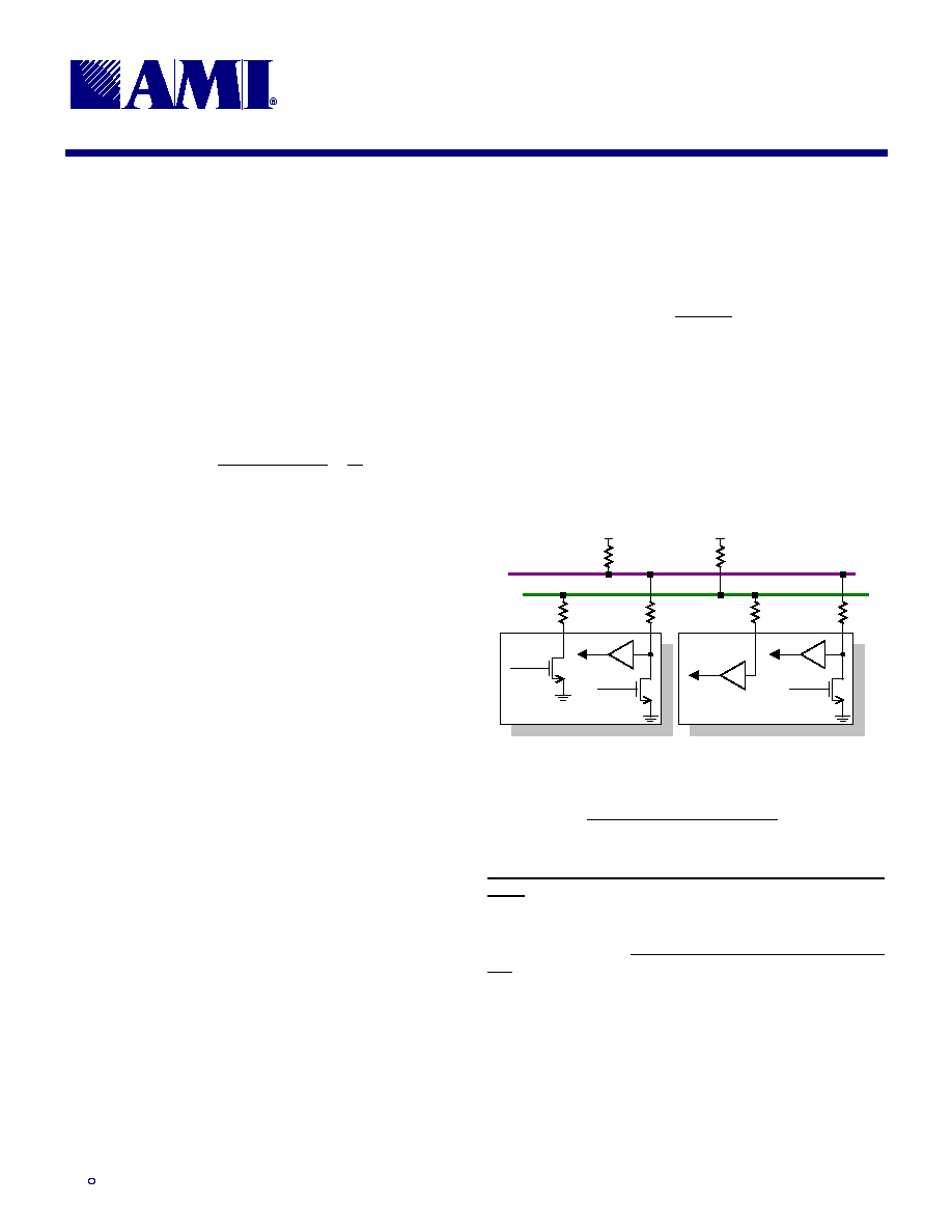
8.3
Serial Communications
Connection of devices to a standard-mode implementa-
tion of either the I
2
C-bus or the SMBus is similar to that
shown in Figure 20. Selection of the pull-up resistors (R
P
)
and the optional series resistors (R
S
) on the SDA and
SCL lines depends on the supply voltage, the bus ca-
pacitance, and the number of connected devices with
their associated input currents.
Control of the clock and data lines is done through open
drain/collector current-sink outputs, and thus requires
external pull-up resistors on both lines. A guideline is
bus
r
P
C
t
R
�
<
2
,
where t
r
is the maximum rise time (minus some margin)
and C
bus
is the total bus capacitance. Assuming an I
2
C
device on each DIMM, an I
2
C controller, the clock buffer,
and two other bus devices results in values in the 5k
to
7k
range. Use of a series resistor to provide protection
against high voltage spikes on the bus will alter the val-
ues for R
P
.
Figure 20: Connections to the Serial Bus
R
P
SDA
SCL
Data In
Data Out
Clock Out
TRANSMITTER
Data In
Data Out
RECEIVER
Clock In
R
P
R
S
(optional)
R
S
(optional)
R
S
(optional)
R
S
(optional)
8.3.1
For More Information
More detailed information on serial bus design can be
obtained from SMBus and I
2
C Bus Design
,
available from
the Intel Corporation at
http://www.intel.com.
Information on the I
2
C-bus can be found in the document
The I
2
C-bus And How To Use It (Including Specifica-
tions), available from Philips Semiconductors at
http://www-us2.semiconductors.philips.com.
Additional information on the System Management Bus
can be found in the System Management Bus Specifica-
tion, available from the Smart Battery System
Implementers' Forum at
http://www.sbs-forum.org.