SAW Resonator
GWR433A
The GWR433A is a true one-por t
surface-acoustic-wave (SAW) resonator in a low-profile TO-39
case. It provides reliable
fundamental-mode
quartz frequency stabilization of fixed-frequency
ransmitters operating at 433.92 MHz.
t
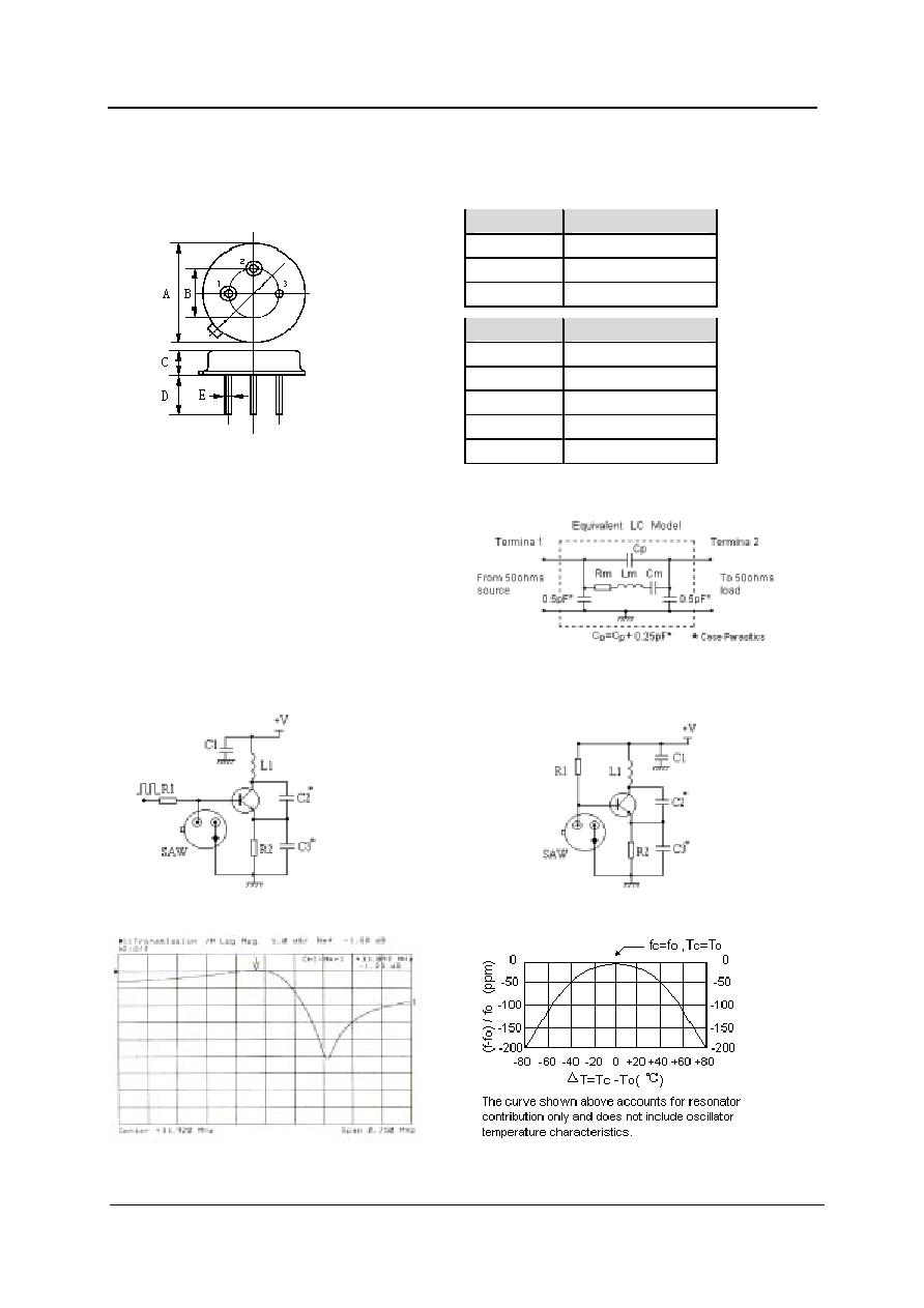
1.Package Dimension
(TO-39)
Dimensions
Data (unit: mm)
A
9.30±0.20
B
5.08±0.10
C
3.40±0.20
D
3±0.20
5±0.20
E
0.45±0.20
Pin
Connection
1
Terminal1
2
Terminal2
3
Case Ground
2.Marking
3.Equivalent LC Model and Test Circuit
GWR433A
Color: Black or Blue
4.Typical Application Circuit
1) Telecontrol Circuitry
2) Local Oscillator Application
5.Typical Frequency Response
6.Temperature Characteristics
Address:NO.120 Bldg,Jindi Industrial Estate,Futian District,Shenzhen,China. Tel:(86)755-26161582 Fax:(86)755-755-26160182 E-mail:guanwi@guanwi.com
GW
SAW Resonator
GWR433A
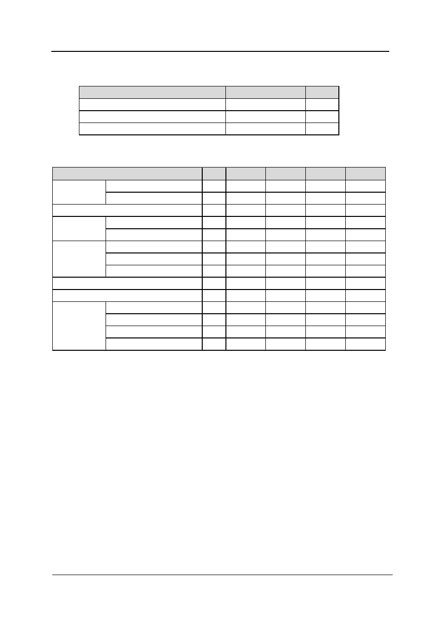
7.Performance
7-1.Maximum Rating
Rating
Value
Units
CW RF Power Dissipation
+10
dBm
DC Voltage Between Any Two Pins
30V
VDC
Case Temperature
-40 to +85
7-2.Electronic Characteristics
Characteristic
Sym
Minimum
Typical
Maximum
Units
Absolute Frequency
f
C
433.845
433.995
MHz
Center Frequency
(+25
)
Tolerance from 433.92 MHz
f
C
75
kHz
Insertion Loss
IL
1.5
2.2
dB
Unloaded Q
Q
U
12,500
Quality Factor
50
Loaded Q
Q
L
2,000
Turnover Temperature
T
O
25
40
55
Turnover Frequency
f
O
fc
kHz
Temperature
Stability
Frequency Temperature Coefficient
FTC
0.037
ppm/
2
Frequency Aging
Absolute Value during the First Year
f
A
10
ppm/yr
DC Insulation Resistance Between Any Two Pins
1.0
M
Motional Resistance
R
M
19
29
Motional Inductance
L
M
120.311
H
Motional Capacitance
C
M
2.1240
fF
RF Equivalent
RLC Model
Pin 1 to Pin 2 Static Capacitance
C
O
2.1
pF
CAUTION: Electrostatic Sensitive Device. Observe precautions for handling !
NOTES:
1.Frequency aging is the change in f
C
with time and is specified
at +65
or less. Aging may exceed the specification for
prolonged temperatures above +65
. Typically, aging is
greatest the first year after manufacture, decreasing in
subsequent years.
2.The center frequency, f
C
,is the frequency of minimum IL with
the resonator in the specified test fixture in a 50
test system
with VSWR
1.2 : 1. Typically, f
oscillator
or f
transmitter
is less
than the resonator f
C
.
3.Typically, equipment utilizing this device requires emissions
testing and government approval, which is the responsibility of
the equipment manufacturer.
4.Unless noted otherwise , case temperature T
C
=+25
2
.
5.The design, manufacturing process, and specifications of this
device are subject to change without notice.
6.Derived mathematically from one or more of the following
directly measured parameters: f
C
, IL, 3 dB bandwidth, f
C
versus T
C
, and C
O
.
7.Turnover temperature, T
O
, is the temperature of maximum (or
turnover) frequency, f
O,
The nominal center frequency at any
case temperature , T
C
, may be calculated from :f = f
O
1-FTC
(T
O
-T
C
)
2
.Typically, oscillator T
O
is 20
less than the
specified resonator T
O
.
8.This
equivalent
RLC
model
approximates
resonator
performance near the resonant frequency and is provided for
reference only . The capacitance C
O
is the measured static
( nonmotional ) capacitance between either pin 1 and ground
or pin 2 and ground .The measurement includes case
parasitic capacitance with a floating case. For usual grounded
case applications (with ground connected to either pin 1 or pin
2 and to the case), add approximately 0.25 pF to C
O
.
Address:NO.120 Bldg,Jindi Industrial Estate,Futian District,Shenzhen,China. Tel:(86)755-26161582 Fax:(86)755-755-26160182 E-mail:guanwi@guanwi.com
GW