 | –≠–ª–µ–∫—Ç—Ä–æ–Ω–Ω—ã–π –∫–æ–º–ø–æ–Ω–µ–Ω—Ç: FLD3F7CZ | –°–∫–∞—á–∞—Ç—å:  PDF PDF  ZIP ZIP |

FEATURES
∑ Direct Modulation DFB Laser
∑ Built-in TEC, Thermistor and Monitor PD
∑ Optical Isolator
∑ 14 Pin Butterfly Type Module
∑ 78 Channel NTSC Loading
(112 Channel device available)
∑ Low Residual CSO & CTB
∑ 11 dB Link Budget Available
APPLICATIONS
This DFB laser is intended for application in analog AM, CATV
at 1,310nm. Transmission spans of 30 km are possible without
amplification.
DESCRIPTION
This DFB laser for analog AM application is a high power laser capable of carrying 78 channels
with excellent CSO, CTB, and CNR performance. It is packaged in a `butterfly' type module.
The module employs a high efficiency optical coupling system, coupling the laser output
through a built-in optical isolator into a single mode fiber pigtail. The module also includes
a monitor photodiode, a thermoelectric cooler (TEC) and a thermistor.
Parameter
LD Forward Current
TEC Voltage
Symbol
Condition
IF
PD Reverse Voltage
VDR
Vc
150
10
+2.5
Ratings
mA
PD Forward Current
IPD
20
V
V
Optical Output Power
Pf
20
CW
CW
mW
mA
LD Reverse Voltage
VR
2
V
Unit
ABSOLUTE MAXIMUM RATINGS (Tc=25∞C, unless otherwise specified)
TEC Current
Ic
95
95
A
260
∞C
Lead Soldering Time
Tsold
10 sec
ATC Operation
Thermistor Temperature
Tth
+65
∞C
Environmental Operating Humidity
Environmental Storage Humidity
Xop
%
%
Storage Temperature
Tstg
+70
-
-
-
-
-
Cooling
-
Heating
+1.4
Cooling
-
Heating
∞C
Operating Case Temperature
Top
+65
-
-
-
-
-
-
-
-
-
-20
-40
-2.0
-
-0.5
-20
∞C
Xst
Top<30
∞C
Tstg<30
∞C
Min.
Max.
Edition 1.2
July 2004
1
1,310nm DFB
CATV Laser
FLD3F7CZ

2
1,310nm DFB
CATV Laser
FLD3F7CZ
Parameter
Threshold Current
Forward Voltage (pin 3-13)
Optical Output Power
Slope Efficiency
Monitor Current
Photodiode Dark Current
Photodiode Capacitance
Peak Wavelength
SideMode Suppression Ratio
Bandwidth (-1dB)
Isolation
Relative Intensity Noise
Composite Second Power
Composite Triple Beat
Carrier to Noise Ratio
Symbol
Ith
VF
Pf
S
Im
Id
Ct
p
SSR
fc
Is
RIN
CSO
CTB
CNR
Tracking Error
Test Conditions
CW
CW, IF=30mA
VDR=5V
VDR=5V, f=1MHz
CW, IF=Iop, VDR=5V
CW, IF=Iop
CW, IF=Iop
CW, IF=Iop
CW
Note (2)
Tc=0 to 65
∞C
Note (3)
Note (4)
Note (1)
TE
mA
V
mW
mW/mA
µA
nA
nm
Unit
dB
GHz
pF
dB
dB/Hz
dBc
dBc
dB
dB
OPTICAL AND ELECTRICAL CHARACTERISTICS (TL=25±1∞C)
Limits
-
-
8
0.20
30
-
-
Min.
1,290
25
1.5
25
-
-
-
50
-0.5
12
Max.
20
1.5
20
-
900
+0.5
100
1,330
-
-
-
-57
-65
-
-155
(1) Total change in Pf over -20<Tc<+65
∞C, Test conditions: Pf=8mW at TL=Tc=25∞C. Constant current operation with TEC operating.
(2) Test condition: Pf=8mW, No matching network is used in the measurement.
(3) Test condition: Pf; same power of Note 4, measuring bandwidth: 45-600MHz, Optical reflection=-40dB (no long-haul fiber is used in the measurement.)
(4) Test condition: Pf=8mW (minimum), Optical Modulation, Index=3.2%/channel (minimum), 78 unmodulated carriers (55.25 to 547.25 MHz;
ch. 2 to 78 plus A-1), Optical link loss=11dB (30 km singlemode fiber), Noise equivalent current of 1st stage of the receiver=7pA/ Hz,
Receiver responsivity=0.86A/W, Optical reflection=-40dB (excluding reflection from long-haul fiber).
Parameter
TEC Current
TEC Voltage
TEC Capacity
Thermistor Resistance
Thermistor B Constant
Symbol
Ic
Vc
T
Rtr
B
Tc = Case Temperature, TL = Laser Temperature
T=40∞C
T=40∞C
-
-
Ic=1A
Test Conditions
A
V
∞C
K
k
Unit
TEC & THERMISTOR CHARACTERISTICS (TL=25±1∞C)
Limits
1.0
2.0
-
10.5
Max.
-
-
40
9.5
Typ. 3,900
Min.
3
1,310nm DFB
CATV Laser
FLD3F7CZ
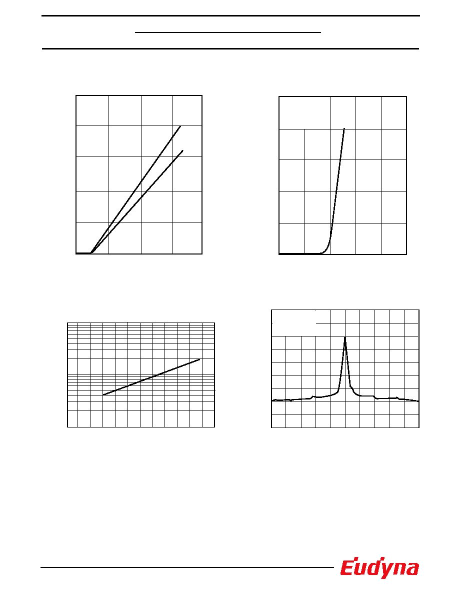
Fig. 1 Optical Output Power and Monitor Current
vs. Laser Forward Current
Fig. 2 Forward Current vs.
Forward Voltage
Fig. 4 Lasing Spectrum
Fig. 3 Temperature Dependence of
Threshold Current
TL=25∞C
Forward Current, IF(mA)
Laser Temperature, TL (∞C)
Forward Voltage, VF (V)
Monitor Current, I
m
(mA)
Forward Current, I
F
(mA)
Relative Intensity (dB)
Threshold Current, Ith(mA)
Optical Output Power, P
f(mW)
25
20
15
10
5
0.2
0.4
0.6
0.8
1.0
Pf
Im
80
60
40
20
100
20
40
60
100
0
0
0.5
1.0
1.5
2.0
2.5
0
-20
0
20
40
60
80
-40
Wavelength (nm)
-20
-40
10
-60
0
10
5
50
20
1310
1320
1300
0
TL=25∞C
Pin 3-13
IF = Iop
TL = 25∞C

4
1,310nm DFB
CATV Laser
FLD3F7CZ
Fig. 5 Tracking Characteristics
TL = 25∞C
IF = Iop
Fig. 6 Frequency Response
Pf = 3mW, CW
BR<-40dB
TL=25∞C
Case Temperature, Tc (∞C)
Frequency (GHz)
Relative Response (dB)
Tracking Error (dB)
Fig. 7 RIN Characteristics
Frequency (GHz)
RIN (dB/Hz)
0.5
0.4
0.3
0.2
0.1
-0.1
-0.2
-0.3
-0.4
-0.5
0
6
3
0
-3
0
20
40
60
80
-20
1.0
2.0
0
1
2
0
-110
-120
-130
-140
-150
-160
-170
Fig. 8 Thermistor Resistance vs. Temperature
Temperature (
∞C)
Thermistor Resistance, R
tr
(K
)
20
50
100
200
10
5
2
1
-20
0
20
40
60
80
-40

5
1,310nm DFB
CATV Laser
FLD3F7CZ
Fig. 9 Cooler voltage and Cooler Current
vs. Case Temperature
Case Temperature, Tc (
∞C)
Cooler Voltage, V
c
(V)
Cooler Current, I
c
(A)
3.0
2.0
1.0
0.0
-1.0
3.0
2.0
1.0
0.0
-1.0
10
20
30
40
50
60
IC
VC
70
80
0
Fig. 10 CSO vs. Output Power
NTSC-78ch. (55.25-547.25MHz)
m=3.5%/ch.
30km SMF (11dB Link)
Optical Output Power, Pf (mW)
CSO (dBc)
-40
-50
-60
-70
-80
5
7
8
6
9
10 11
12 13 14 15
548.5MHz
54MHz
194.5MHz
Fig. 11 CTB vs. Output Power
Optical Output Power, Pf (mW)
CTB (dBc)
NTSC-78ch. (55.25-547.25MHz)
m=3.5%/ch.
30km SMF (11dB Link)
55 & 547 MHz
313 MHz
-40
-50
-60
-70
-80
5
7
8
6
9
10 11 12 13 14 15
Fig. 12 CNR vs. Output Power
Optical Output Power, Pf (mW)
CNR (dB)
NTSC-78ch. (55.25-547.25MHz)
m=3.5%/ch.
30km SMF (11dB Link)
55 MHz
313 & 547 MHz
60
50
40
5
7
8
6
9
10 11 12 13 14 15