Excelics
EFA160A
DATA SHEET
Low Distortion GaAs Power FET
∑
+29.0dBm TYPICAL OUTPUT POWER
∑
9.0dB TYPICAL POWER GAIN AT 12GHz
∑
0.3 X 1600 MICRON RECESSED
"MUSHROOM" GATE
∑
Si
3
N
4
PASSIVATION
∑
ADVANCED EPITAXIAL DOPING PROFILE
PROVIDES HIGH POWER EFFICIENCY,
LINEARITY AND RELIABILITY
∑
Idss SORTED IN 30mA PER BIN RANGE
ELECTRICAL CHARACTERISTICS (T
a
= 25
O
C)
SYMBOLS PARAMETERS/TEST
CONDITIONS MIN
TYP
MAX
UNIT
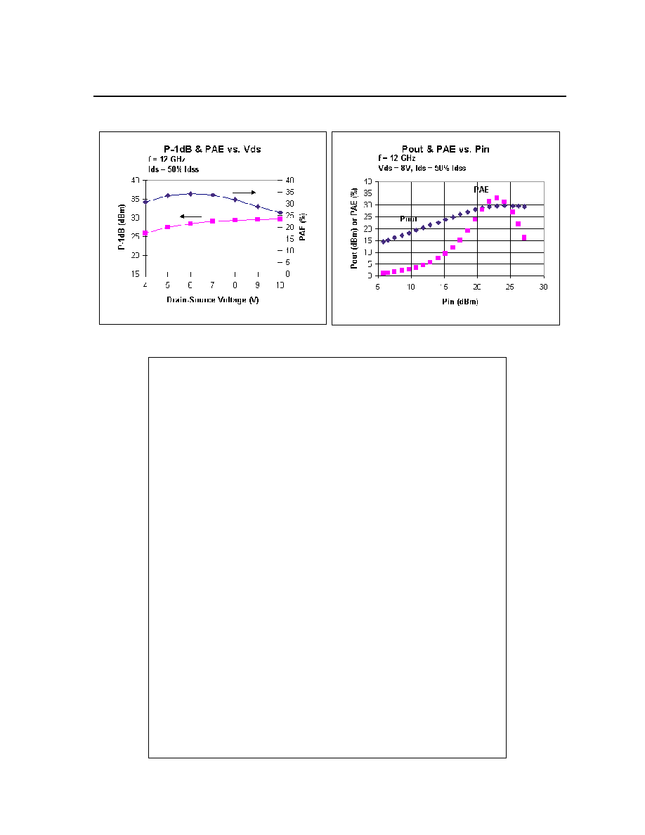
P
1dB
Output Power at 1dB Compression f=12GHz
Vds=8V, Ids=50% Idss f=18GHz
27.0 29.0
29.0
dBm
G
1dB
Gain at 1dB Compression f=12GHz
Vds=8V, Ids=50% Idss f=18GHz
7.0 9.0
6.5
dB
PAE
Gain at 1dB Compression
Vds=8V, Ids=50% Idss f=12GHz
34
%
Idss
Saturated Drain Current Vds=3V, Vgs=0V
260
420
600
mA
Gm
Transconductance Vds=3V, Vgs=0V
180
240
mS
Vp
Pinch-off Voltage Vds=3V, Ids=4.0mA
-2.0
-3.5
V
BVgd
Drain Breakdown Voltage Igd=1.6mA
-12
-15
V
BVgs
Source Breakdown Voltage Igs=1.6mA
-7
-14
V
Rth
Thermal Resistance (Au-Sn Eutectic Attach)
30
o
C/W
MAXIMUM RATINGS AT 25
O
C
SYMBOLS PARAMETERS ABSOLUTE
1
CONTINUOUS
2
Vds
Drain-Source Voltage
12V
8V
Vgs
Gate-Source Voltage
-8V
-4V
Ids
Drain Current
Idss
475mA
Igsf
Forward Gate Current
40mA
7mA
Pin
Input Power
28dBm
@ 3dB Compression
Tch
Channel Temperature
175
o
C
150
o
C
Tstg
Storage Temperature
-65/175
o
C
-65/150
o
C
Pt
Total Power Dissipation
4.5W
3.8W
Note: 1. Exceeding any of the above ratings may result in permanent damage.
2. Exceeding any of the above ratings may reduce MTTF below design goals.
Excelics Semiconductor, Inc., 2908 Scott Blvd., Santa Clara, CA 95054
Phone: (408) 970-8664 Fax: (408) 970-8998 Web Site: www.excelics.com
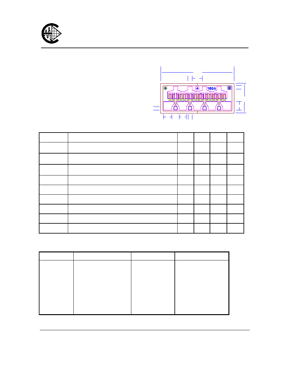
Chip Thickness: 75
±
13 microns
All Dimensions In Microns
50
50
48
100
95
40
840
340
116
80
G
G
G
G
D
D
D
D
S
S
S
S
S
EFA160A
DATA SHEET
Low Distortion GaAs Power FET
S-PARAMETERS
8V, 1/2 Idss
FREQ --- S11 --- --- S21 --- --- S12 --- --- S22 ---
(GHz) MAG ANG MAG ANG MAG ANG MAG ANG
1.0 0.936 -81.9 9.025 133.3 0.035 48.7 0.221 -106.2
2.0 0.911 -119.8 5.964 108.8 0.047 27.7 0.285 -132.0
3.0 0.903 -138.7 4.275 94.5 0.050 18.4 0.319 -141.6
4.0 0.903 -149.8 3.297 84.3 0.050 13.0 0.347 -145.0
5.0 0.900 -157.8 2.644 75.5 0.049 9.3 0.382 -147.5
6.0 0.903 -162.4 2.207 68.6 0.048 6.4 0.413 -148.0
7.0 0.905 -165.8 1.884 62.3 0.047 5.6 0.445 -148.7
8.0 0.908 -168.0 1.640 56.4 0.046 3.6 0.476 -149.5
9.0 0.913 -170.0 1.451 51.2 0.044 3.1 0.510 -150.4
10.0 0.914 -171.8 1.297 46.2 0.042 3.9 0.536 -151.0
11.0 0.918 -173.7 1.172 41.0 0.041 3.2 0.563 -152.2
12.0 0.920 -175.2 1.067 36.1 0.039 2.6 0.592 -153.8
13.0 0.924 -177.4 0.977 31.0 0.038 2.9 0.612 -155.2
14.0 0.925 -179.9 0.901 25.9 0.038 1.8 0.635 -157.2
15.0 0.925 177.5 0.836 20.8 0.038 1.6 0.653 -159.4
16.0 0.929 174.2 0.775 15.4 0.038 0.7 0.675 -161.8
17.0 0.927 171.0 0.721 10.0 0.037 1.5 0.688 -164.7
18.0 0.928 167.6 0.670 4.6 0.037 2.2 0.706 -167.7
19.0 0.927 164.8 0.626 -0.6 0.037 1.4 0.721 -171.1
20.0 0.931 162.1 0.580 -5.4 0.037 1.0 0.738 -174.6
21.0 0.945 162.3 0.502 -9.7 0.036 2.4 0.771 -178.4
22.0 0.951 161.1 0.469 -13.0 0.033 2.9 0.786 178.6
23.0 0.960 159.9 0.433 -16.9 0.035 5.0 0.803 176.2
24.0 0.961 159.6 0.409 -20.1 0.037 8.9 0.821 174.3
25.0 0.973 159.3 0.391 -22.7 0.037 10.9 0.831 172.5
26.0 0.969 159.6 0.368 -24.8 0.039 10.8 0.849 170.6
Note: The data included 0.7 mils diameter Au bonding wires:
4 gate wires, 15 mils each; 4 drain wires, 20 mils each; 10 source wires, 7 mils each.