
©2001 Fairchild Semiconductor Corporation
FFPF60B150DS
Rev. A, March 2001
DAMPER + MODULATION DIODE
Absolute Maximum Ratings (Modulation)
T
C
=25
∞
∞
∞
∞
C unless otherwise noted
Absolute Maximum Ratings (Damper)
T
C
=25
∞
∞
∞
∞
C unless otherwise noted
Thermal Characteristics
Symbol
Parameter
Value
Units
V
RRM
Peak Repetitive Reverse Voltage
600
V
I
F(AV)
Average Rectified Forward Current @ T
C
= 100
∞
C
20
A
I
FSM
Non-repetitive Peak Surge Current
60Hz Single Half-Sine Wave
120
A
T
J,
T
STG
Operating Junction and Storage Temperature
- 65 to +150
∞
C
Symbol
Parameter
Value
Units
V
RRM
Peak Repetitive Reverse Voltage
1500
V
I
F(AV)
Average Rectified Forward Current @ T
C
= 100
∞
C
6
A
I
FSM
Non-repetitive Peak Surge Current
60Hz Single Half-Sine Wave
60
A
T
J,
T
STG
Operating Junction and Storage Temperature
- 65 to +150
∞
C
Symbol
Parameter
Value
Units
R
JC
Maximum Thermal Resistance, Junction to Case
3.3
∞
C/W
FFPF60B150DS
Features
∑ High voltage and high reliability
∑ High speed switching
Modulation diode / Damper diode
∑ Low conduction loss
Modulation diode / Damper diode
Applications
∑ (Modulation + Damper) diode designed for
horizontal deflection circuits in C-TVs &
monitors
Damper Modulation
TO-220F
1 2 3

©2001 Fairchild Semiconductor Corporation
Rev. A, March 2001
FFPF60B150DS
Electrical Characteristics*(Modulation)
T
C
=25
∞
∞
∞
∞
C unless otherwise noted
* Pulse Test: Pulse Width=300
µ
s, Duty Cycle
=
2%
Electrical Characteristics*(Damper)
T
C
=25
∞
∞
∞
∞
C unless otherwise noted
* Pulse Test: Pulse Width=300
µ
s, Duty Cycle
=
2%
Symbol
Parameter
Min.
Typ.
Max.
Units
V
FM
Maximum Instantaneous Forward Voltage
I
F
= 20A
I
F
= 20A
T
C
= 25
∞
C
T
C
= 100
∞
C
2.2
2.0
V
I
RM
Maximum Instantaneous Reverse Current
@ rated V
R
T
C
= 25
∞
C
T
C
= 100
∞
C
10
100
µ
A
t
rr
I
rr
Q
rr
Maximum Reverse Recovery Time
Maximum Reverse Recovery Current
Maximum Reverse Recovery Charge
(I
F
=20A, di/dt = 200A/
µ
s)
90
8
360
ns
A
nC
Symbol
Parameter
Min
Typ
Max
Units
V
FM
Maximum Instantaneous Forward Voltage
I
F
= 6A
I
F
= 6A
T
C
= 25
∞
C
T
C
= 100
∞
C
1.6
1.4
V
I
RM
Maximum Instantaneous Reverse Current
@ rated V
R
T
C
= 25
∞
C
T
C
= 100
∞
C
7
60
µ
A
t
rr
Maximum Reverse Recovery Time
(I
F
=1.0A, di/dt = 50A/
µ
s)
170
ns
t
fr
Maximum Forward Recovery Time
(I
F
=6.5A, di/dt = 50A/
µ
s)
350
ns
V
FRM
Maximum Forward Recovery Voltage
17
V

©2001 Fairchild Semiconductor Corporation
Rev. A, March 2001
FFPF60B150DS
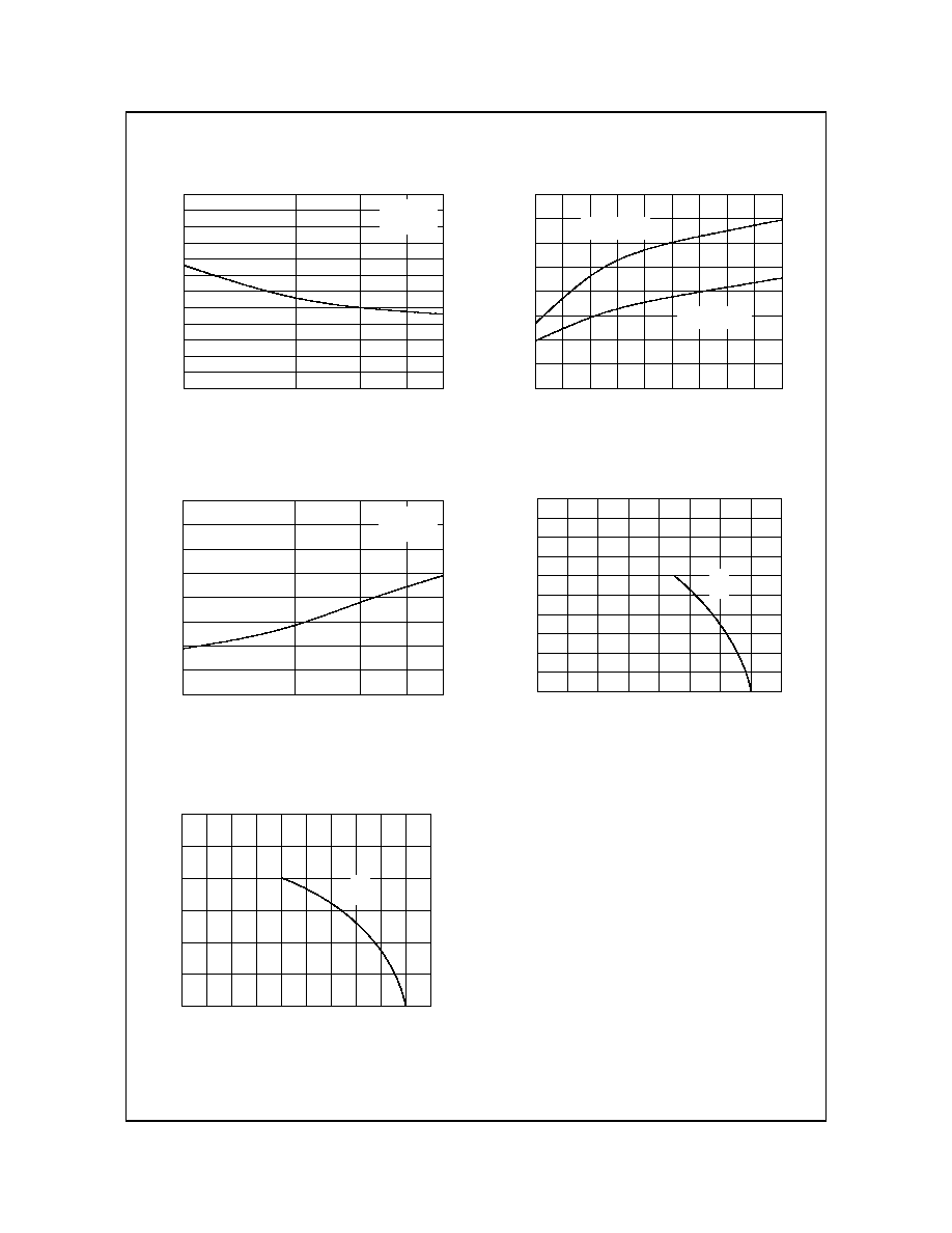
Typical Characteristics
Figure 1. Typical Forward Characteristics
(Modulation Diode)
Figure 3. Typical Reverse Current
vs. Reverse Voltage (Modulation Diode)
Figure 5. Typical Junction Capacitance
(Modulation Diode)
Figure 2. Typical Forward Characteristics
(Damper Diode)
Figure 4. Typical Reverse Current
vs. Reverse Voltage (Damper Diode)
Figure 6. Typical Junction Capacitance
(Damper Diode)
0.1
1
10
40
0.0
0.5
1.0
1.5
2.0
2.5
3.0
T
C
= 25
o
C
T
C
= 100
o
C
Forward Voltage , V
F
[V]
F
o
rw
ard Cu
rr
e
n
t , I
F
[A
]
100
200
300
400
500
600
0.001
0.01
0.1
1
10
100
1000
T
C
= 100
o
C
T
C
= 25
o
C
R
e
v
e
rs
e
C
u
rre
n
t
,
I
R
[u
A
]
Reverse Voltage , V
R
[V]
0.1
1
10
100
1
50
100
150
200
Typical Capacitance
at 0V = 178 pF
Capac
i
t
anc
e ,
Cj
[
p
F
]
Reverse Voltage , V
R
[V]
0.1
1
10
50
0.0
0.4
0.8
1.2
1.6
2.0
T
J
= 25
o
C
T
J
= 125
o
C
Forward Voltage , V
F
[V]
F
o
rw
a
r
d
C
u
rr
e
n
t
,
I
F
[A
]
0
300
600
900
1200
1500
0.001
0.01
0.1
1
10
100
T
J
= 100
o
C
T
J
= 125
o
C
T
J
= 25
o
C
Rev
e
r
s
e Cu
r
r
ent
,
I
R
[
µ
A]
Reverse Voltage , V
R
[V]
0.1
1
10
100
0
20
40
60
80
100
120
Typical Capacitance
at 0V = 100 pF
Ca
pac
i
t
a
n
c
e
,
Cj
[
p
F]
Reverse Voltage , V
R
[V]
©2001 Fairchild Semiconductor Corporation
Rev. A, March 2001
FFPF60B150DS
Typical Characteristics
Figure 7. Typical Reverse Recovery Time
vs. di/dt (Modulation Diode)
Figure 9. Typical Reverse Recovery Current
vs. di/dt (Modulation Diode)
Figure 11. Forward Current Derating Curve
(Modulation Diode)
Figure 8. Typical Reverse Recovery Time
vs. di/dt (Damper Diode)
Figure 10. Forward Current Derating Curve
(Damper Diode)
100
500
40
50
60
70
80
90
100
I
F
= 20A
T
C
= 25
o
C
R
e
ve
r
s
e
Re
co
ve
r
y
T
i
m
e
,
t
rr
[n
s
]
di/dt [A/us]
100
500
0
2
4
6
8
10
12
14
16
I
F
= 20A
T
C
= 25
o
C
Re
v
e
r
s
e
Re
c
o
v
e
r
y
Cu
r
r
e
nt
,
I
rr
[A
]
di/dt [A/us]
60
80
100
120
140
160
0
5
10
15
20
25
30
DC
A
v
er
age F
o
r
w
ar
d Cur
r
ent
,
I
F(
AV)
[A
]
Case Temperature , T
C
[
o
C]
1
2
3
4
5
6
7
8
9
10
0
100
200
300
400
di/dt = 100A/
µ
s
di/dt = 50A/
µ
s
R
e
ve
rse
R
e
co
ve
ry T
i
m
e
,
t
rr
[n
s
]
Forward Current , I
F
[A]
80
100
120
140
160
0
1
2
3
4
5
6
7
8
9
10
DC
A
v
e
r
a
g
e
F
o
r
w
a
r
d
C
u
r
r
e
n
t
, I
F(
A
V
)
[A
]
Case Temperature , T
C
[
o
C]

©2001 Fairchild Semiconductor Corporation
Rev. A, March 2001
FFPF60B150DS
Package Dimensions
Dimensions in Millimeters
TO-220F
(7.00)
(0.70)
MAX1.47
(30
∞
)
#1
3.30
±
0.10
15.80
±
0.20
15.87
±
0.20
6.68
±
0.20
9.75
±
0.30
4.70
±
0.20
10.16
±
0.20
(1.00x45
∞
)
2.54
±
0.20
0.80
±
0.10
9.40
±
0.20
2.76
±
0.20
0.35
±
0.10
¯3.18
±
0.10
2.54TYP
[2.54
±
0.20
]
2.54TYP
[2.54
±
0.20
]
0.50
+0.10
≠0.05