©2001 Fairchild Semiconductor Corporation
www.fairchildsemi.com
Rev. 1.0.2
Features
∑ Operation from 3.0 to 40V input
∑ Short circuit current limiting
∑ Low standby current
∑ Output switch current of 1.5A without external transistors
∑ Output voltage adjustable
∑ Frequency of operation from 100Hz to 100KHz
∑ Step up, Step down or inverting switching regulators
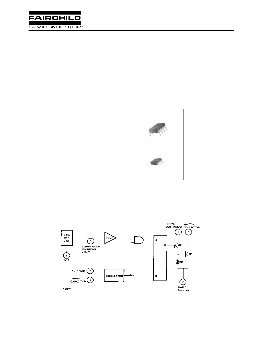
Description
The MC34063A/MC33063A is a monolithic regulator sub
system intended for use as DC to DC converter. This device
contains a temperature compensated bandgap reference, a
duty cycle control oscillator, driver and high current output
switch. It can be used for step down, step up or inverting
switching regulators as well as for series pass regulators.
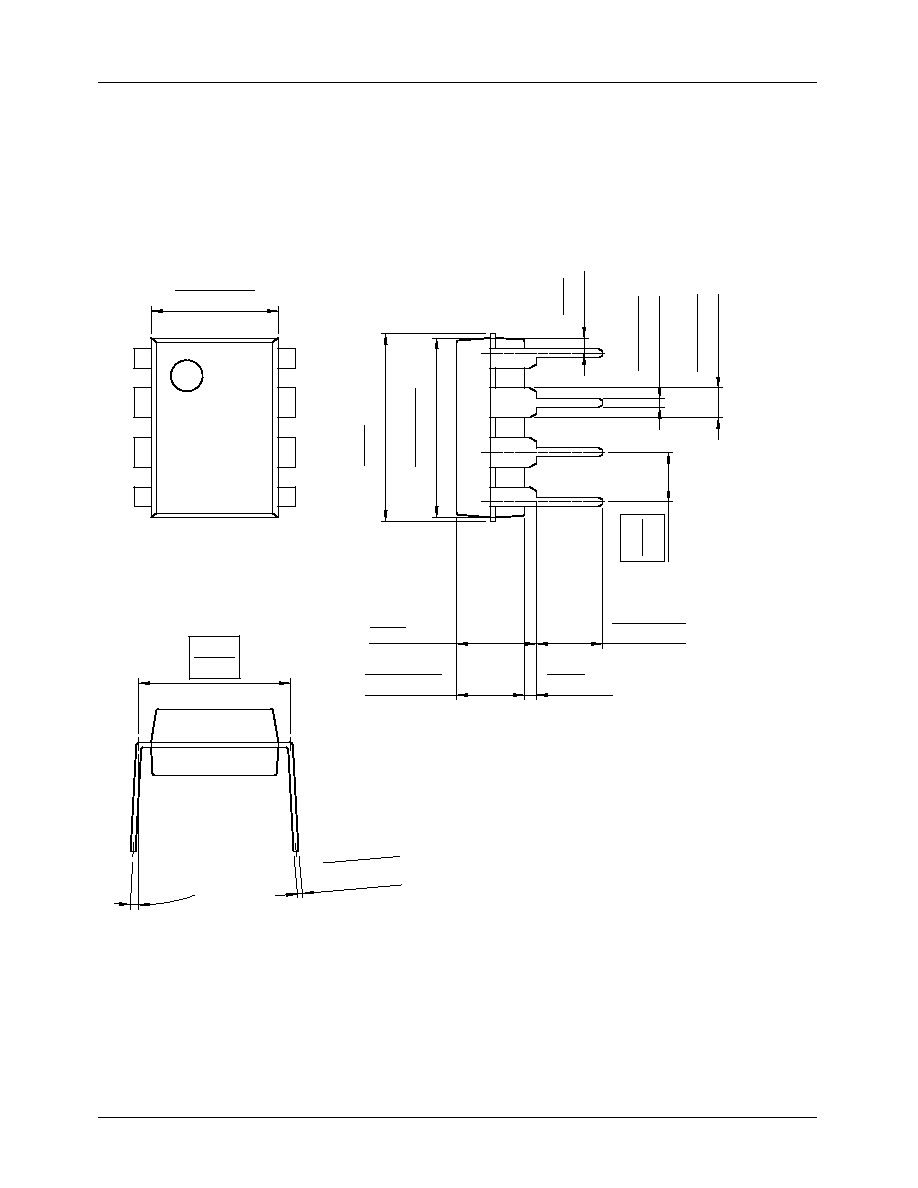
8-DIP
8-SOP
1
1
Internal Block Diagram
MC34063A/MC33063A
SMPS Controller

MC34063A/MC33063A
2
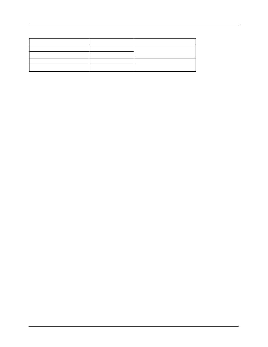
Absolute Maximum Ratings
Electrical Characteristics
(V
CC
= 5.0V, T
A
= 0
∞
C to +70
∞
C
for the MC34063, T
A
= -40
∞
C to the +85
∞
C for the MC33063, unless otherwise
specified)
Note :
Output switch tests are performed under pulsed conditions to minimize power dissipation
Parameter
Symbol
Value
Unit
Supply Voltage
V
CC
40
V
Comparator Input Voltage Range
V
I(COMP)
- 0.3 ~ + 40
V
Switch Collector Voltage
V
C(SW)
40
V
Switch Emitter Voltage
V
E(SW)
40
V
Switch Collector To Emitter Voltage
V
CE(SW)
40
V
Driver Collector Voltage
V
C(DR)
40
V
Switch Current
I
SW
1.5
A
Storage Temperature Range
T
STG
- 65 ~ + 150
∞
C
Parameter
Symbol
Conditions
Min. Typ. Max. Unit
OSCILLATOR
Charging Current
I
CHG
V
CC
= 5 to 40V
T
A
= 25
∞
C
22
31
42
µ
A
Discharging Current
I
DISCHG
V
CC
= 5 to 40V
T
A
= 25
∞
C
140
190
260
µ
A
Oscillator Amplitude
V
(OSC)
T
A
= 25
∞
C
-
0.5
-
V
Discharge To Charge Current Ratio
K
V
7
= V
CC ,
T
A
= 25
∞
C
5.2
6.1
7.5
-
Current Limit Sense
Voltage
V
SENSE(C.L)
I
CHG
= I
DISCHG
T
A
= 25
∞
C
250
300
350
mV
OUTPUT SWITCH
Saturation Voltage 1 (Note)
V
CE(SAT)
1
I
SW
= 1.0A
V
C
(driver) = V
C
(SW)
-
0.95
1.3
V
Saturation Voltage 2 (Note)
V
CE(SAT)
2
I
SW
= 1.0A,
V
C
(driver) = 50mA
-
0.45
0.7
V
DC Current Gain (Note)
G
I(DC)
I
SW
= 1.0A,
V
CE
= 5.0V, T
A
= 25
∞
C
50
180
-
-
Collector off State Current (Note)
I
C(OFF)
V
CE
= 40V, T
A
= 25
∞
C
-
0.01
100
µ
A
COMPARATOR
Threshold Voltage
V
TH
-
1.21 1.24 1.29
V
Threshold Voltage Line Regulation
V
TH
V
CC
= 3 to 40V
-
2.0
5.0
mV
Input Bias Current
I
BIAS
V
I
= 0V
-
50
400
nA
TOTAL DEVICE
Supply Current
MC34063
I
CC
V
CC
= 5 to 40V
C
T
= 0.001uF
V
7
= V
CC,
V
5
>V
TH
pin2 = GND
-
-
4.0
mA
MC33063
-
-
5.0

MC34063A/MC33063A
6/21/01 0.0m 001
Stock#DSxxxxxxxx
2001 Fairchild Semiconductor Corporation
LIFE SUPPORT POLICY
FAIRCHILD'S PRODUCTS ARE NOT AUTHORIZED FOR USE AS CRITICAL COMPONENTS IN LIFE SUPPORT DEVICES
OR SYSTEMS WITHOUT THE EXPRESS WRITTEN APPROVAL OF THE PRESIDENT OF FAIRCHILD SEMICONDUCTOR
CORPORATION. As used herein:
1. Life support devices or systems are devices or systems
which, (a) are intended for surgical implant into the body,
or (b) support or sustain life, and (c) whose failure to
perform when properly used in accordance with
instructions for use provided in the labeling, can be
reasonably expected to result in a significant injury of the
user.
2. A critical component in any component of a life support
device or system whose failure to perform can be
reasonably expected to cause the failure of the life support
device or system, or to affect its safety or effectiveness.
www.fairchildsemi.com
DISCLAIMER
FAIRCHILD SEMICONDUCTOR RESERVES THE RIGHT TO MAKE CHANGES WITHOUT FURTHER NOTICE TO ANY
PRODUCTS HEREIN TO IMPROVE RELIABILITY, FUNCTION OR DESIGN. FAIRCHILD DOES NOT ASSUME ANY
LIABILITY ARISING OUT OF THE APPLICATION OR USE OF ANY PRODUCT OR CIRCUIT DESCRIBED HEREIN; NEITHER
DOES IT CONVEY ANY LICENSE UNDER ITS PATENT RIGHTS, NOR THE RIGHTS OF OTHERS.