 | ÐлекÑÑоннÑй компоненÑ: MSQC6912C | СкаÑаÑÑ:  PDF PDF  ZIP ZIP |
Äîêóìåíòàöèÿ è îïèñàíèÿ www.docs.chipfind.ru
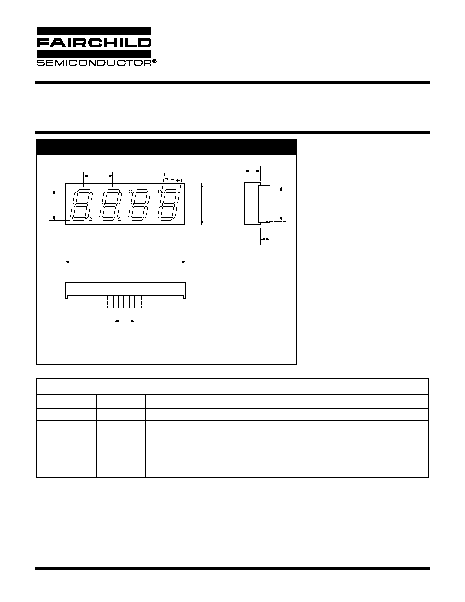
PACKAGE DIMENSIONS
14mm (0.56 inch) Four Digit
MULTIPLEX CLOCK STICK DISPLAY
Bright Red MSQC6112C, MSQC6142C
High Efficiency Red MSQC6912C, MSQC6942C
Green MSQC6412C, MSQC6442C
7/2/03
Page 1 of 7
© 2002 Fairchild Semiconductor Corporation
12.70
50.40 (1.980)
MSQC6XX2C YWW LL H
8.00
(0.300)
2.54 X 4
= 10.16 (0.400)
4.30
(0.170)
14.20
(0.560)
17.10
(0.673)
15.24 (0.600)
7.90
(0.311)
10°
(0.500)
(For other colour options, contact your local area Sales Manager)
MODELS AVAILABLE
Part Number
Colour
Description
MSQC6112C
Bright Red
Clock Display, Common Anode, gray face, neutral segments
MSQC6142C
Bright Red
Clock Display, Common Cathode, gray face, neutral segments
MSQC6412C
Green
Clock Display, Common Anode, gray face, green segments
MSQC6442C
Green
Clock Display, Common Cathode, gray face, green segments
MSQC6912C
H.E.R
Clock Display, Common Anode, gray face, neutral segements
MSQC6942C
H.E.R.
Clock Display, Common Cathode, gray face, neutral segments
Features
·
Bright Bold Segments
·
Common Anode/Cathode
·
Low Power Consumption
·
Low Current Capability
·
High Performance
·
High Reliability
Applications
·
Appliances
·
Automotive
·
Instrumentation
·
Process Control
NOTES:
· Dimensions are in mm (inches)
· All Pins 0.5 (0.020) Diameter
· Tolerances are ±0.25mm (0.010") unless otherwise stated.
Notes:
7/2/03
Page 2 of 7
© 2002 Fairchild Semiconductor Corporation
14mm (0.56 inch) Four Digit
MULTIPLEX CLOCK STICK DISPLAY
BRIGHT RED MSQC6112C, MSQC6142C
HIGH EFFICIENCY RED MSQC6912C, MSQC6942C
GREEN MSQC6412C, MSQC6442C
NOTES:
(1) Data per individual LED element
(2) Luminous intensity (ucd) = average light output per segment
(3) B = breakdown
ABSOLUTE MAXIMUM RATINGS
(1)
(T
A
= 25°C, unless otherwise specified)
Part Number
Parameter
MSQC6112C
MSQC6142C
MSQC6412C
MSQC6442C
MSQC6912C
MSQC6942C
Units
Continuous Forward Current
(each segment)
15 25 25
mA
Peak Forward Current
(F = 10KHz, D/F = 1/10)
60 90 90
mA
Power Dissipation (P
D
)
40 70 70
mW
*Derate Linearly from 25°C
0.17 0.33 0.33
mW
Reverse Voltage per Die
5 Volts
Operating and Storage Temperature Range
-40°C to +85°C
Lead soldering time (1/16 inch from standoffs)
5 seconds @ 230°C
ELECTRO-OPTICAL CHARACTERISTICS
(1)
(T
A
= 25°C, unless otherwise specified)
Part Number
Parameter
MSQC6112C
MSQC6142C
MSQC6412C
MSQC6442C
MSQC6912C
MSQC6912C
Units
Test
Condition
Luminous intensity
(2)
(I
V
)
Minimum (Standard Current)
300
800
800
µcd
I
F
= 10mA
Typical (Standard Current)
700
2400
2000
µcd
I
F
= 10mA
Minimum (Low Current)
Not Available
Typical (Low Current)
Not Available
Forward Voltage (V
F
)
Typical (Standard Current)
2.10
2.10
2.00
V
I
F
= 20mA
Maximum (Standard Current)
2.80
2.80
2.80
V
I
F
= 20mA
Typical (Low Current)
Not Available
Maximum (Low Current)
Not Available
Peak Wavelength
695 570 635
nm
I
F
= 20mA
Dominant Wavelength
Not Available
Spectral Line 1/2 Width
90 30 45
nm
I
F
= 10mA
Reverse B
(3)
. Voltage (V
R
)
5 5 5
V
I
R
= 100uA
7/2/03
Page 3 of 7
© 2002 Fairchild Semiconductor Corporation
14mm (0.56 inch) Four Digit
MULTIPLEX CLOCK STICK DISPLAY
BRIGHT RED MSQC6112C, MSQC6142C
HIGH EFFICIENCY RED MSQC6912C, MSQC6942C
GREEN MSQC6412C, MSQC6442C
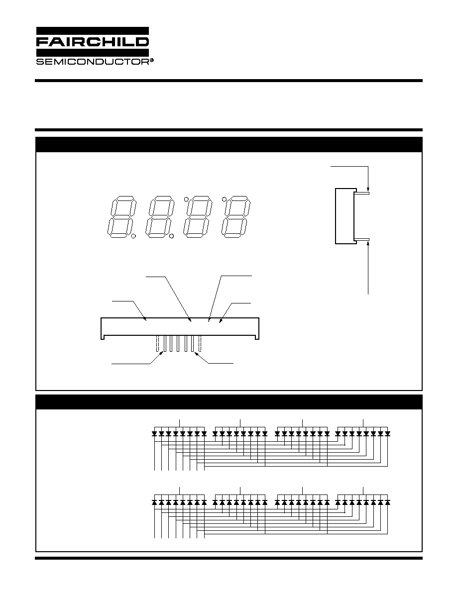
PIN ORIENTATION, SEGMENT IDENTIFICATION, AND PRODUCT MARKING
MSQC6XX2C YWW LL H
A
Digit 1
Date Code
Part Number
Pin #1
Pin #6
Light Category
Note Five pins on one side Seven Pins on the other
Pin #5
Pin #5
Hue Wavelength
Green Only
Digit 2
Digit 3
Digit 4
F
E
D
C
G
B
Dp1
Dp2
Dp3
Dp4
SCHEMATICS
MSQC6X10C
(Common Anode)
(Common Cathode)
MSQC6X40C
Digit 1
Digit 2
12
A B C D E
F G Dp
11 7
4
2
1 10 5
3
A B C D E
F G Dp
11 7
4
2
1 10 5
3
9
8
6
Digit 3
Digit 4
Digit 1
Digit 2
12
9
8
6
Digit 3
Digit 4

7/2/03
Page 4 of 7
© 2002 Fairchild Semiconductor Corporation
14mm (0.56 inch) Four Digit
MULTIPLEX CLOCK STICK DISPLAY
BRIGHT RED MSQC6112C, MSQC6142C
HIGH EFFICIENCY RED MSQC6912C, MSQC6942C
GREEN MSQC6412C, MSQC6442C
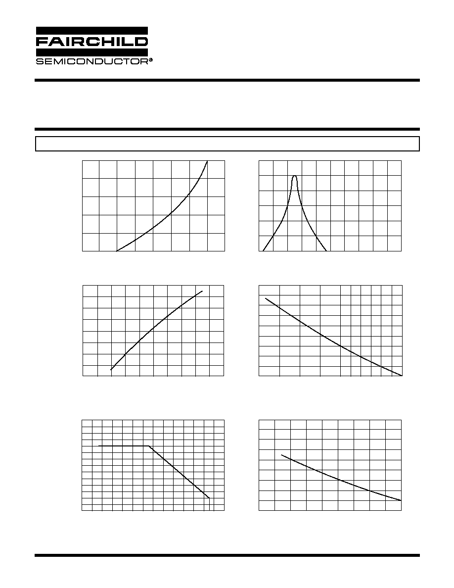
GRAPHICAL DATA Bright Red (T
A
= 25°C, unless otherwise specified)
50
40
30
20
10
0
2.50
2.25
2.00
1.50
1.25
1.00
0.50
0.25
0
35
15
20
25
30
10
5
0
80
100
120
60
40
20
0
1.2
1.6
2.0
2.4
2.8
0
10
20
30
40
50
-40
-20
0
20
40
60
80
100
600
640
680
720
760
800
Forward Voltage (V
F
) - Volts
Fig. 1 Forward Current vs. Forward Voltage
I
F
- Forward Current - mA
Fig. 3 Relative Luminous Intensity vs. Forward Current
T
A
AMBIENT TEMPERATURE
°C
Fig. 4 Maximum Allowable DC Current per Segment vs.
a Function of Ambient Temperature
10
20
40
DC
Duty Cycle % Per Segment
(Average I
F
= 10mA)
Fig. 5 Luminous Intensity vs. Duty Cycle
1
3
5
10
20
50
100
Duty Cycle %
Fig. 6 Max Peak Current vs. Duty Cycle %
(Refresh Rate f=1 KHz)
Wavelength (
)-nm
Fig. 2 Spectral Response
Forward Current (I
F
=mA)
IDCMAX-Maximum DC Current - mA
500
1000
200
100
50
75
25
10
Peak I
P
- mA
2
1.5
1
Relative Intensity
Relative Output-%
Luminous Intensity Relative
To Value AT = 20mA
7/2/03
Page 5 of 7
© 2002 Fairchild Semiconductor Corporation
14mm (0.56 inch) Four Digit
MULTIPLEX CLOCK STICK DISPLAY
BRIGHT RED MSQC6112C, MSQC6142C
HIGH EFFICIENCY RED MSQC6912C, MSQC6942C
GREEN MSQC6412C, MSQC6442C
GRAPHICAL DATA Green (T
A
= 25°C, unless otherwise specified)
50
40
30
20
10
0
2.50
2.25
2.00
1.50
1.25
1.00
0.50
0.25
0
35
15
20
25
30
10
5
0
80
100
120
60
40
20
0
1.2
1.6
2.0
2.4
2.8
0
10
20
30
40
50
-40
-20
0
20
40
60
80
100
520
560
600
640
680
720
Forward Voltage (V
F
) - Volts
Fig. 1 Forward Current vs. Forward Voltage
I
F
- Forward Current - mA
Fig. 3 Relative Luminous Intensity vs. Forward Current
T
A
AMBIENT TEMPERATURE
°C
Fig. 4 Maximum Allowable DC Current per Segment vs.
a Function of Ambient Temperature
10
20
40
DC
Duty Cycle % Per Segment
(Average I
F
= 10mA)
Fig. 5 Luminous Intensity vs. Duty Cycle
1
3
5
10
20
50
100
Duty Cycle %
Fig. 6 Max Peak Current vs. Duty Cycle %
(Refresh Rate f=1 KHz)
Wavelength (
)-nm
Fig. 2 Spectral Response
Forward Current (I
F
=mA)
IDCMAX-Maximum DC Current - mA
500
1000
200
100
50
75
25
10
Peak I
P
- mA
2
1.5
1
Relative Intensity
Relative Output-%
Luminous Intensity Relative
To Value AT = 20mA