 | –≠–ª–µ–∫—Ç—Ä–æ–Ω–Ω—ã–π –∫–æ–º–ø–æ–Ω–µ–Ω—Ç: NZT660 | –°–∫–∞—á–∞—Ç—å:  PDF PDF  ZIP ZIP |

July 1998
NZT660 / NZT660A
PNP Low Saturation Transistor
These devices are designed with high current gain and low saturation voltage with collector currents up to 3A
continuous.
Absolute Maximum Ratings*
T
A = 25∞C unless otherwise noted
∞C
-55 to +150
Operating and Storage Junction Temperature Range
T
J,
T
stg
A
3
Collector Current - Continuous
I
C
V
5
Emitter-Base Voltage
V
EBO
V
80
Collector-Base Voltage
V
CBO
V
60
Collector-Emitter Voltage
V
CEO
Units
NZT660/NZT660A
Parameter
Symbol
*These ratings are limiting values above which the serviceability of any semiconductor device may be impaired.
NOTES:
1) These ratings are based on a maximum junction temperature of 150∞C.
2) These are steady state limits. The factory should be consulted on applications involving pulsed or low duty cycle operations.
Thermal Characteristics
T
A = 25∞C unless otherwise noted
∞C/W
62.5
Thermal Resistance, Junction to Ambient
R
JA
W
2
Total Device Dissipation
P
D
NZT660/NZT660A
Units
Max
Characteristic
Symbol
Nzt660.lwpPrPA 7/10/98 revC
C
E
C
B
SOT-223
N
ZT660/
N
ZT660
A
©
1998 Fairchild Semiconductor Corporation

-
75
I
C
= 100 mA,V
CE
= 5 V, f=100MHz
Transition Frequency
f
T
pF
45
V
CB
= 10 V, I
E
= 0, f = 1MHz
Output Capacitance
C
obo
SMALL SIGNAL CHARACTERISTICS
V
1
I
C
= 1 A, V
CE
= 2 V
Base-Emitter On Voltage
V
BE(on)
V
1.25
I
C
= 1 A, I
B
= 100 mA
Base-Emitter Saturation Voltage
V
BE(sat)
mV
300
550
500
I
C
= 1 A, I
B
= 100 mA
I
C
= 3 A, I
B
= 300 mA
NZT660
NZT660A
Collector-Emitter Saturation Voltage
V
CE(sat)
-
300
550
70
100
250
80
25
I
C
= 100 mA, V
CE
= 2 V
I
C
= 500 mA, V
CE
= 2 V
NZT660
NZT660A
I
C
= 1 A, V
CE
= 2 V
I
C
= 3 A, V
CE
= 2 V
DC Current Gain
h
FE
ON CHARACTERISTICS*
nA
100
V
EB
= 4V
Emitter Cutoff Current
I
EBO
nA
uA
100
10
V
CB
= 30 V
V
CB
= 30 V, T
A
=100∞C
Collector Cutoff Current
I
CBO
V
5
I
E
= 100
µ
A
Emitter-Base Breakdown Voltage
BV
EBO
V
80
I
C
= 100
µ
A
Collector-Base Breakdown Voltage
BV
CBO
V
60
I
C
= 10 mA
Collector-Emitter Breakdown Voltage
BV
CEO
OFF CHARACTERISTICS
Units
Max
Min
Test Conditions
Parameter
Symbol
PNP Low Saturation Transistor
(continued)
Electrical Characteristics
T
A = 25∞C unless otherwise noted
*Pulse Test: Pulse Width
300
µ
s, Duty Cycle
2.0%
Nzt660.lwpPrPA 7/10/98 revC
N
ZT660/
N
ZT660
A

Typical Characteristics
Current Gain vs. Collector Current
0.0001
0.001
0.01
0.1
1
10
0
100
200
300
400
500
600
700
800
900
1000
I - COLLECTOR CURRENT (mA)
H
- CU
RRE
NT
G
A
IN
C
FE
25∞C
125∞C
- 40∞C
V = 2.0V
ce
Collector-Emitter Saturation
Voltage vs Collector Current
0.01
0.1
1
10
0
0.1
0.2
0.3
0.4
0.5
0.6
0.7
0.8
I - COLLECTOR CURRENT (mA)
V
-
C
O
LLEC
T
O
R
-
E
M
I
TT
ER
V
O
L
T
A
G
E
(
V
)
C
CE
S
A
T
- 40∞C
25∞C
125∞C
= 10
Input/Output Capacitance vs.
Reverse Bias Voltage
0.1
0.5
1
10
20
50
100
0
50
100
150
200
250
300
350
400
V - COLLECTOR VOLTAGE (V)
CA
P
A
C
I
T
A
N
C
E
(
p
f
)
CE
V = 2.0V
ce
C
ibo
C
obo
f = 1.0MHz
Base-Emitter Saturation
Voltage vs Collector Current
0.001
0.01
0.1
1
10
0.2
0.4
0.6
0.8
1
1.2
1.4
I - COLLECTOR CURRENT (A)
V
-
B
AS
E
-
E
M
I
TTE
R
SA
TUR
A
TI
O
N
V
O
L
T
A
G
E(
V)
C
B
E
S
A
T
25∞C
- 40∞C
125∞C
= 10
Base-Emitter On Voltage vs.
Collector Current
0.0001
0.001
0.01
0.1
1
10
0.2
0.4
0.6
0.8
1
1.2
1.4
1.6
I - COLLECTOR CURRENT (A)
V
-
B
A
SE
-
E
M
I
T
T
E
R
O
N
V
O
LT
AG
E (
V
)
C
BE
O
N
25∞C
- 40∞C
125∞C
V = 2.0V
ce
PA

SOT-223 Packaging
Configuration: Figure 1.0
Components
Leader Tape
500mm minimum or
62 empty pockets
Trailer Tape
300mm minimum or
38 empty pockets
SOT-223 Tape Leader and Trailer
Configuration: Figure 2.0
Cover Tape
Carrier Tape
Note/Comments
Packaging Option
SOT-223 Packaging Information
Standard
(no flow code)
D84Z
Packaging type
Reel Size
TNR
13" Dia
TNR
7" Dia
Qty per Reel/Tube/Bag
2,500
500
Box Dimension (mm)
343x64x343
184x187x47
Max qty per Box
5,000
1,000
Weight per unit (gm)
0.1246
0.1246
Weight per Reel (kg)
0.7250
0.1532
SOT-223 Unit Orientation
F852
014
F852
014
F852
014
F852
014
F63TNR Label
343mm x 342mm x 64mm
Intermediate box for Standard
184mm x 184mm x 47mm
Pizza Box for D84Z Option
F63TNR Label
LOT: CBVK741B019
FSID: PN2222A
D/C1: D9842 QTY1:
SPEC REV:
SPEC:
QTY: 3000
D/C2:
QTY2:
CPN:
N/F: F (F63TNR)3
F63TNR Label sample
F63TNR Label
Antistatic Cover Tape
Customized Label
Static Dissipative
Embossed Carrier Tape
Packaging Description:
SOT-223 parts are shipped in tape. The carrier tape is
made from a dissipative (carbon filled) polycarbonate
resin. The cover tape is a multilayer film (Heat Activated
Adhesive in nature) primarily composed of polyester film,
adhesive layer, sealant, and anti-static sprayed agent.
These reeled parts in standard option are shipped with
2,500 units per 13" or 330cm diameter reel. The reels are
dark blue in color and is made of polystyrene plastic (anti-
static coated). Other option comes in 500 units per 7" or
177cm diameter reel. This and some other options are
further described in the Packaging Information table.
These full reels are individually barcode labeled and
placed inside a standard intermediate box (illustrated in
figure 1.0) made of recyclable corrugated brown paper.
One box contains two reels maximum. And these boxes
are placed inside a barcode labeled shipping box which
comes in different sizes depending on the number of parts
shipped.
SOT-223 Tape and Reel Data and Package Dimensions
September 1999, Rev. B
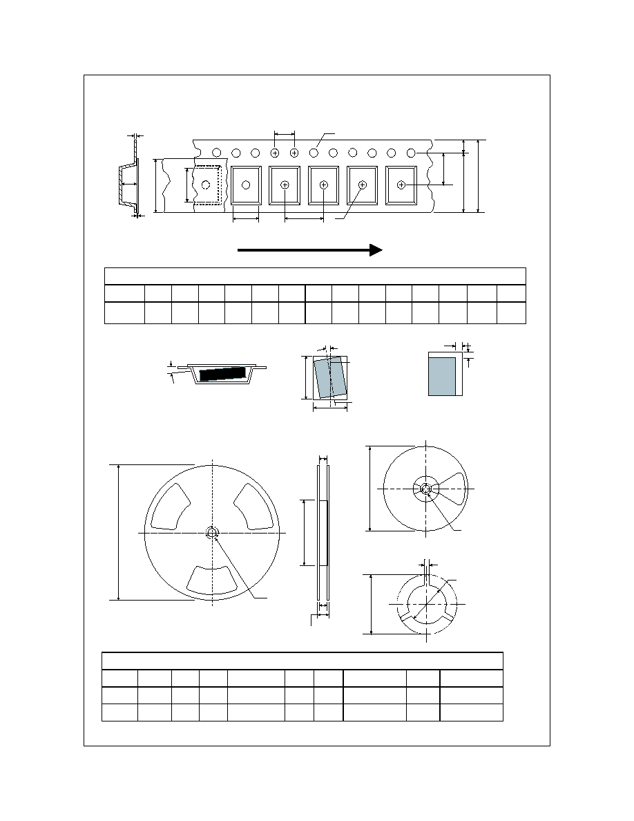
Dimensions are in millimeter
Pkg type
A0
B0
W
D0
D1
E1
E2
F
P1
P0
K0
T
Wc
Tc
SOT-223
(12mm)
6.83
+/-0.10
7.42
+/-0.10
12.0
+/-0.3
1.55
+/-0.05
1.50
+/-0.10
1.75
+/-0.10
10.25
min
5.50
+/-0.05
8.0
+/-0.1
4.0
+/-0.1
1.88
+/-0.10
0.292
+/-
0.0130
9.5
+/-0.025
0.06
+/-0.02
P1
A0
D1
P0
F
W
E1
D0
E2
B0
Tc
Wc
K0
T
Dimensions are in inches and millimeters
Tape Size
Reel
Option
Dim A
Dim B
Dim C
Dim D
Dim N
Dim W1
Dim W2
Dim W3 (LSL-USL)
12mm
7" Dia
7.00
177.8
0.059
1.5
512 +0.020/-0.008
13 +0.5/-0.2
0.795
20.2
5.906
150
0.488 +0.078/-0.000
12.4 +2/0
0.724
18.4
0.469 ≠ 0.606
11.9 ≠ 15.4
12mm
13" Dia
13.00
330
0.059
1.5
512 +0.020/-0.008
13 +0.5/-0.2
0.795
20.2
7.00
178
0.488 +0.078/-0.000
12.4 +2/0
0.724
18.4
0.469 ≠ 0.606
11.9 ≠ 15.4
See detail AA
Dim A
max
13" Diameter Option
7" Diameter Option
Dim A
Max
See detail AA
W3
W2 max Measured at Hub
W1 Measured at Hub
Dim N
Dim D
min
Dim C
B Min
DETAIL AA
Notes: A0, B0, and K0 dimensions are determined with respect to the EIA/Jedec RS-481
rotational and lateral movement requirements (see sketches A, B, and C).
20 deg maximum component rotation
0.5mm
maximum
0.5mm
maximum
Sketch C (Top View)
Component lateral movement
Typical
component
cavity
center line
20 deg maximum
Typical
component
center line
B0
A0
Sketch B (Top View)
Component Rotation
Sketch A (Side or Front Sectional View)
Component Rotation
User Direction of Feed
SOT-223 Embossed Carrier Tape
Configuration: Figure 3.0
SOT-223 Reel Configuration: Figure 4.0
SOT-223 Tape and Reel Data and Package Dimensions, continued
July 1999, Rev. B