 | ÐлекÑÑоннÑй компоненÑ: SS16 | СкаÑаÑÑ:  PDF PDF  ZIP ZIP |
Äîêóìåíòàöèÿ è îïèñàíèÿ www.docs.chipfind.ru
SS12-S100
SS12-S100, Rev. A1
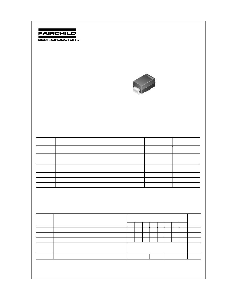
SS12 - S100
1.0 Ampere Schottky Barrier Rectifiers
Absolute Maximum Ratings*
T
A
= 25°C unless otherwise noted
*
These ratings are limiting values above which the serviceability of any semiconductor device may be impaired.
**
Device mounted on FR-4 PCB 0.013 mm.
Electrical Characteristics
T
A
= 25°C unless otherwise noted
2001 Fairchild Semiconductor Corporation
Features
·
Glass passivated junctions.
·
High current capability, low V
F
.
·
For use in low voltage, high
frequency inverters free
wheeling, and polarity
protection applications.
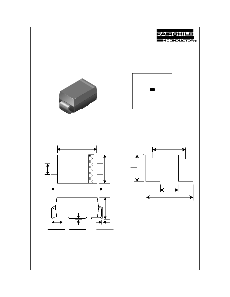
SMA/DO-214AC
COLOR BAND DENOTES CATHODE
Symbol
Parameter
Value
Units
I
F(AV)
Average Rectified Current
.375 " lead length @ T
A
= 75
°C
1.0 A
I
FSM
Non-repetitive Peak Forward Surge Current
8.3 ms single half-sine-wave
Superimposed on rated load (JEDEC method)
40
A
P
D
Total
Device
Dissipation
Derate
above
25
°C
1.1
11
W
mW/
°C
R
JA
Thermal Resistance, Junction to Ambient **
88
°C/W
T
stg
Storage Temperature Range
-65 to +150
°C
T
J
Operating Junction Temperature
-65 to +125
°C
Symbol
Parameter
Device
Units
12 13 14 15 16 18 19 100
V
RRM
Maximum Repetitive Reverse Voltage
20 30 40 50 60 80 90 100
V
V
RMS
Maximum RMS Voltage
14 21 28 35 42 56 64 71
V
V
R
DC Reverse Voltage (Rated V
R
)
20 30 40 50 60 80 90 100 V
I
RM
Maximum Instantaneous Reverse Current
T
A
= 25
°C
(Note 1)
@ rated V
R
T
A
= 100
°C
0.2
10
mA
mA
V
FM
Maximum Instantaneous Forward Voltage @ 1.0 A
500
700
850
mV
Note: Pulse Test: Pulse Width
300 µs, Duty Cycle 2.0%
SS12-S100
SS12-S100, Rev. A1
Schottky Barrier Rectifiers
(continued)
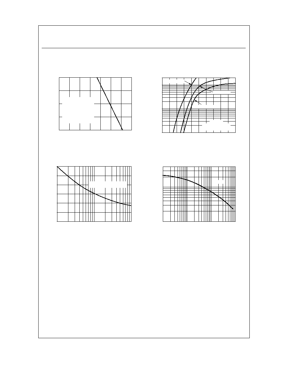
Typical Characteristics
Forward Current Derating Curve
0
20
40
60
80
100
120
140
0
0.25
0.5
0.75
1
LEAD TEMPERATURE ( C)
FO
RW
AR
D CU
RRE
NT
(
A
)
º
SINGLE PHASE
HALF WAVE
60Hz
RESISTIVE OR
INDUCTIVE LOAD
P.C.B. MOUNTED
ON 0.2x0.2"(5.0x5.0mm)
COPPER PAD AREAS
Non-Repetitive Surge Current
1
2
5
10
20
50
100
0
5
10
15
20
25
30
NUMBER OF CYCLES AT 60Hz
F
O
R
W
A
R
D
S
URG
E
CU
RR
E
N
T
(
A
)
8.3ms Single Half Sine-Wave
JEDEC Method
Junction Capacitance
0.1
0.5
1
5
10
50 100
10
20
30
40
50
100
200
400
REVERSE VOLTAGE (V)
C
A
PA
C
I
TA
N
C
E (
p
F
)
T = 25 C
º
J
Forward Characteristics
0
0.2 0.4 0.6 0.8
1
1.2 1.4 1.6 1.8
2
0.1
1
5
10
20
FORWARD VOLTAGE (V)
F
O
R
W
AR
D CU
RR
E
N
T
(
A
)
Pulse Width = 300
µ
µ
µ
µS
1% Duty Cycle
T = 25 C
º
J
SS15 - SS16
SS18 - S100
SS12 - SS14
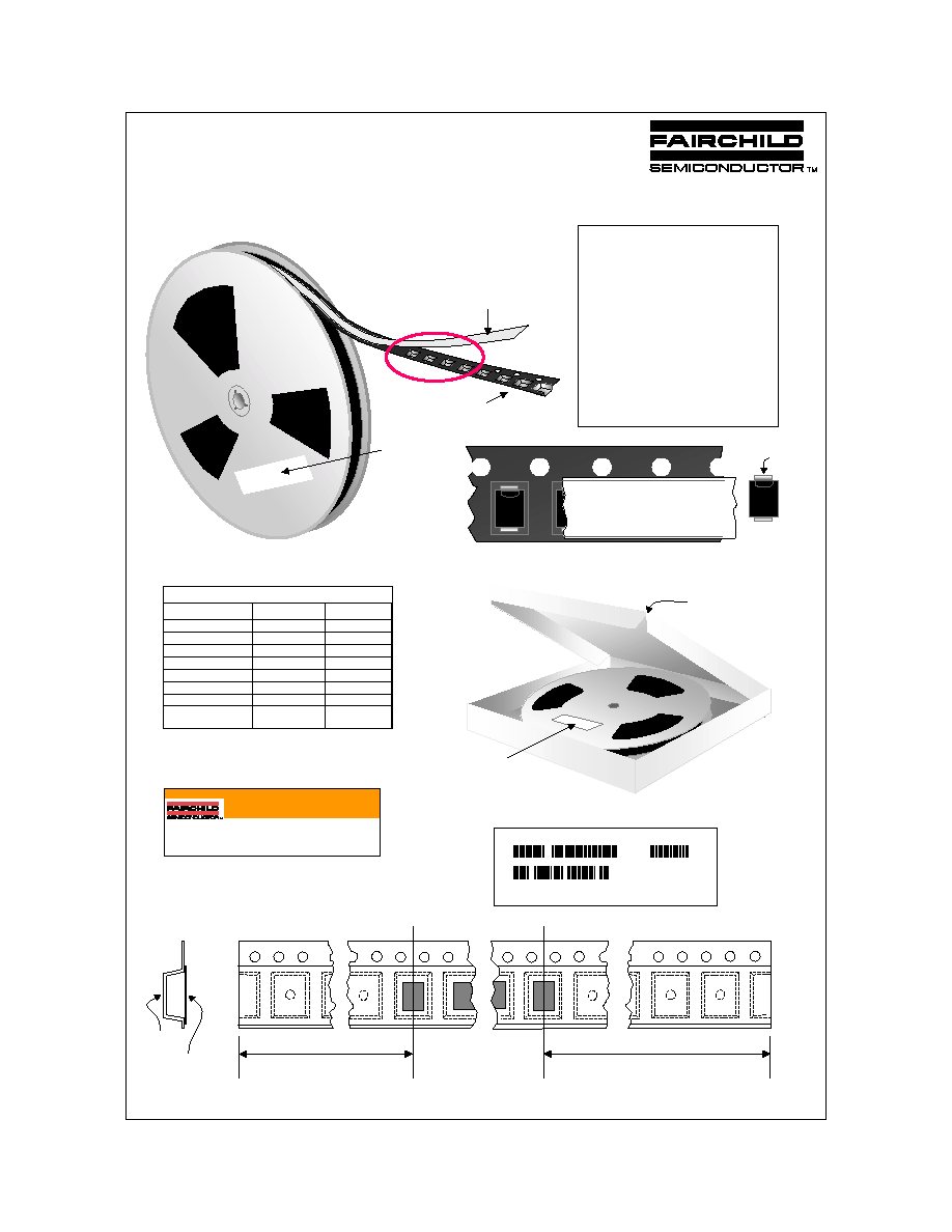
DO-214AC(SMA) Tape and Reel Data
July 2000, Rev. A
©2000 Fairchild Semiconductor International
DO-214AC(SMA) Packaging
Configuration: Figure 1.0
Components
DO-214AC(SMA) Tape Leader and Trailer
Configuration: Figure 2.0
Cover Tape
Carrier Tape
Cathode
F
924
18L3
F
924
18L3
F
924
18L3
F
924
18L3
F
924
18L3
Human
Readable
/Barcode
Label
Antistatic Cover Tape
Embossed Carrier Tape
Leader Tape
390mm minim m
Trailer Tape
160mm minim m or
Human Readable Label sample
336mm x 336mm x 38mm
Intermediate container for 13" reel option
Human
Readable/Barcode
Label (on top)
F63TNR Label sample
DO-214AC(SMA) Packaging Information
Note/Comments
Packaging Option
Packaging type
Reel Size (inch diameter)
Qty per Reel/Tube/Bag
Box Dimension (mm)
Max qty per Box
Weight per unit (gm)
Weight per Reel (kg)
Human readable label
Under package
code P5
TNR
13
7,500
336X336X38
15,000
0.064
0.860
Barcode label
Under package
code MA
TNR
13
5,000
340X350X340
10,000
0.064
0.750
Human readable/barcode Label
LOT: CBVK741B019
FSID: FMKA140
D/C1: T0012
QTY1:
SPEC REV:
SPEC:
QTY: 7500
D/C2:
QTY2:
CPN:
FAIRCHILD SEMICONDUCTOR INTERNATIONAL
(F63TNR)3.2
Packaging Description:
DO-214AC(SMA) parts are shipped in tape. The carrier
t a p e i s m a d e f r o m a d i s s i p a t i v e ( c a r b o n f i l l e d )
polycarbonate resin. Alternate carrier tape is made of anti-
static plastic. The cover tape is a multilayer film (Heat
Activated Adhesive in nature) primarily composed of
polyester film, adhesive layer, sealant, and anti-static
sprayed agent. These reeled parts in standard option are
shipped with 7,500 units per 13" or 330cm diameter reel.
The reel comes in plastic or carton which is made of
polystyrene plastic (anti-static coated) and thick white
paper respectively. Further information is described in the
Packaging Information table.
These full reels are individually labeled and placed inside
a bleach box (illustrated in figure 1.0) made of recyclable
carton paper with a Fairchild logo printing. One box
contains two reels maximum. Certain number of these
boxes are placed inside shipping box which comes in
different sizes depending on the number of parts shipped.
DO-214AC(SMA) unit orientation
CAUTION: This container provides protection for static sensitive devices. Handle devices with caution upon removal.
MADE IN ONE OR MORE OF THE FOLLOWING COUNTRIES: PHILIPPINES (MACTAN,
EXPORT PROCESSING ZONE), MALAYSIA, CHINA, S. KOREA, TAIWAN, THAILAND,
SINGAPORE AND JAPAN.
ANTI-STATIC
FMKA140
I.D.
Qty
D/C
Lot
T0012
CBVK741B019
7500
July 2000, Rev. A
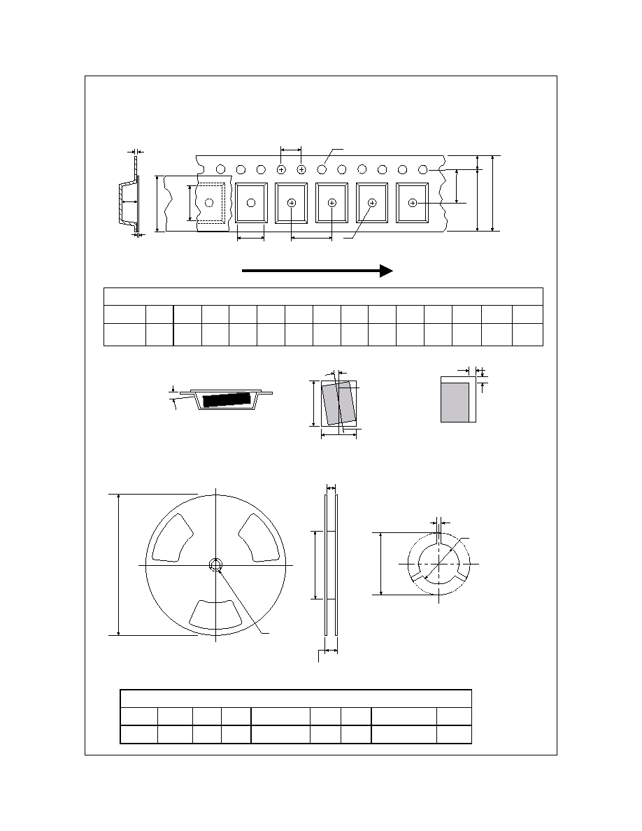
DO-214AC(SMA) Tape and Reel Data, continued
Dimensions are in millimeter
Pkg type
A0
B0
W
D0
D1
E1
E2
F
P1
P0
K0
T
Wc
Tc
DO-214AC(SMA)
(12mm)
2.72
+/-0.10
5.25
+/-0.10
12.0
+/-0.3
1.55
+/-0.05
1.125
+/-0.125
1.75
+/-0.10
10.25
min
5.5
+/-0.05
4.0
+/-0.1
4.0
+/-0.1
2.45
+/-0.10
0.23
+/-0.10
9.3
+/-0.025
0.06
+/-0.02
P1
A0
D1
P0
F
W
E1
D0
E2
B0
Tc
Wc
K0
T
Dimensions are in inches and millimeters
Tape Size
Reel
Option
Dim A
Dim B
Dim C
Dim D
Dim N
Dim W1
Dim W2
12mm
Dia
13"
13.0
330
0.059
1.5
512 +0.020/-0.008
13 +0.5/-0.2
0.795
20.2
1.97
50 min
0.331 +0.059/-0.000
8.4 +1.5/0
0.567
14.4
See detail AA
Dim A
max
13" Diameter Option
W2 max Measured at Hub
W1 Measured at Hub
Dim N
Dim D
min
Dim C
B Min
DETAIL AA
Notes: A0, B0, and K0 dimensions are determined with respect to the EIA/Jedec RS-481
rotational and lateral movement requirements (see sketches A, B, and C).
20 deg maximum component rotation
0.5mm
maximum
0.5mm
maximum
Sketch C (Top View)
Component lateral movement
Typical
component
cavity
center line
20 deg maximum
Typical
component
center line
B0
A0
Sketch B (Top View)
Component Rotation
Sketch A (Side or Front Sectional View)
Component Rotation
User Direction of Feed
DO-214AC(SMA) Embossed Carrier Tape
Configuration: Figure 3.0
DO-214AC(SMA) Reel Configuration:
Figure 4.0
DO-214AC(SMA) (FS PKG Code P5)
DO-214AC(SMA) Package Dimensions
August 1999, Rev. A
1:1
Scale 1:1 on letter size paper
Dimensions shown below are in:
inches [millimeters]
Part Weight per unit (gram): 0.064
©2000 Fairchild Semiconductor International
2
1
0.208 (5.283)
0.188 (4.775)
0.181 (4.597)
0.157 (3.988)
0.096 (2.438)
0.078 (1.981)
0.062 (1.575)
0.055 (1.397)
0.008 (0.203)
0.002 (0.051)
0.012 (0.305)
0.006 (0.152)
0.060 (1.524)
0.030 (0.762)
0.114 (2.896)
0.098 (2.489)
+
3.93
3.73
1.67
1.47
2.38
2.18
5.49
5.29
Minimum Recommended
Land Pattern